2002 NISSAN PATROL lock
[x] Cancel search: lockPage 25 of 311

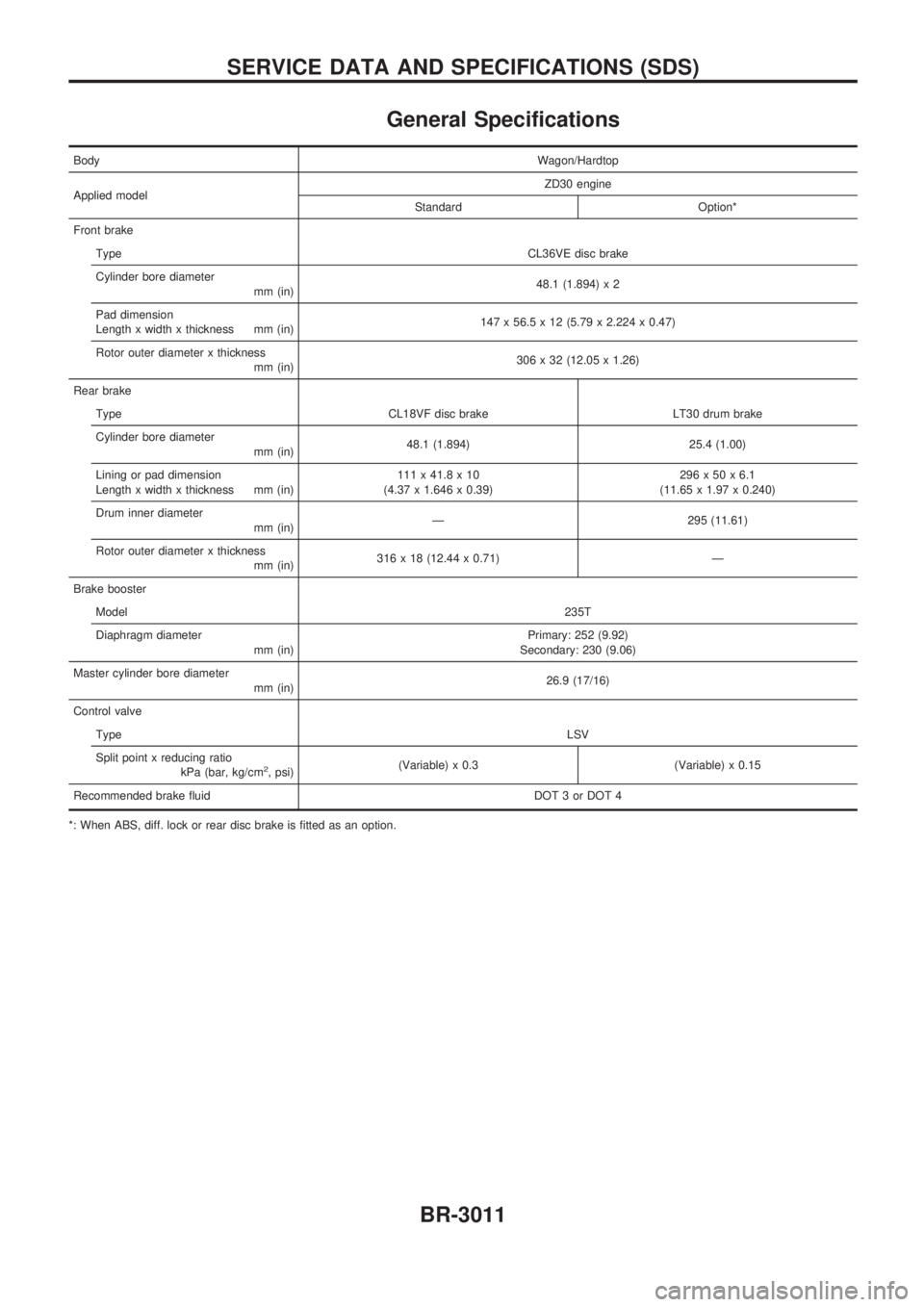
General Specifications
BodyWagon/Hardtop
Applied modelZD30 engine
Standard Option*
Front brake
TypeCL36VE disc brake
Cylinder bore diameter
mm (in)48.1 (1.894) x 2
Pad dimension
Length x width x thickness mm (in)147 x 56.5 x 12 (5.79 x 2.224 x 0.47)
Rotor outer diameter x thickness
mm (in)306 x 32 (12.05 x 1.26)
Rear brake
Type CL18VF disc brake LT30 drum brake
Cylinder bore diameter
mm (in)48.1 (1.894) 25.4 (1.00)
Lining or pad dimension
Length x width x thickness mm (in)111 x 41.8 x 10
(4.37 x 1.646 x 0.39)296x50x6.1
(11.65 x 1.97 x 0.240)
Drum inner diameter
mm (in)Ð 295 (11.61)
Rotor outer diameter x thickness
mm (in)316 x 18 (12.44 x 0.71) Ð
Brake booster
Model235T
Diaphragm diameter
mm (in)Primary: 252 (9.92)
Secondary: 230 (9.06)
Master cylinder bore diameter
mm (in)26.9 (17/16)
Control valve
TypeLSV
Split point x reducing ratio
kPa (bar, kg/cm
2, psi)(Variable) x 0.3 (Variable) x 0.15
Recommended brake fluid DOT 3 or DOT 4
*: When ABS, diff. lock or rear disc brake is fitted as an option.
SERVICE DATA AND SPECIFICATIONS (SDS)
BR-3011
Page 34 of 311

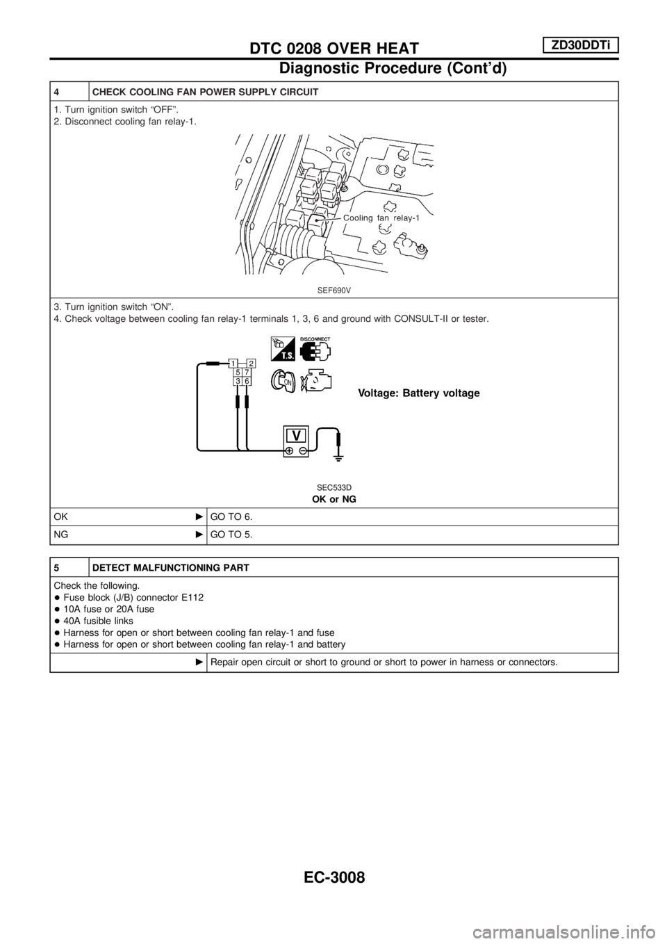
4 CHECK COOLING FAN POWER SUPPLY CIRCUIT
1. Turn ignition switch ªOFFº.
2. Disconnect cooling fan relay-1.
SEF690V
3. Turn ignition switch ªONº.
4. Check voltage between cooling fan relay-1 terminals 1, 3, 6 and ground with CONSULT-II or tester.
SEC533D
OK or NG
OKcGO TO 6.
NGcGO TO 5.
5 DETECT MALFUNCTIONING PART
Check the following.
+Fuse block (J/B) connector E112
+10A fuse or 20A fuse
+40A fusible links
+Harness for open or short between cooling fan relay-1 and fuse
+Harness for open or short between cooling fan relay-1 and battery
cRepair open circuit or short to ground or short to power in harness or connectors.
DTC 0208 OVER HEATZD30DDTi
Diagnostic Procedure (Cont'd)
EC-3008
Page 40 of 311

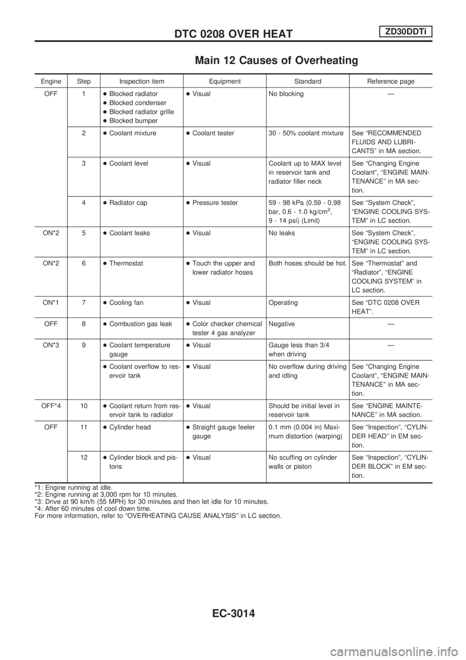
Main 12 Causes of Overheating
Engine Step Inspection item Equipment Standard Reference page
OFF 1+Blocked radiator
+Blocked condenser
+Blocked radiator grille
+Blocked bumper+Visual No blocking Ð
2+Coolant mixture+Coolant tester 30 - 50% coolant mixture See ªRECOMMENDED
FLUIDS AND LUBRI-
CANTSº in MA section.
3+Coolant level+Visual Coolant up to MAX level
in reservoir tank and
radiator filler neckSee ªChanging Engine
Coolantº, ªENGINE MAIN-
TENANCEº in MA sec-
tion.
4+Radiator cap+Pressure tester 59 - 98 kPa (0.59 - 0.98
bar, 0.6 - 1.0 kg/cm
2,
9 - 14 psi) (Limit)See ªSystem Checkº,
ªENGINE COOLING SYS-
TEMº in LC section.
ON*2 5+Coolant leaks+Visual No leaks See ªSystem Checkº,
ªENGINE COOLING SYS-
TEMº in LC section.
ON*2 6+Thermostat+Touch the upper and
lower radiator hosesBoth hoses should be hot. See ªThermostatº and
ªRadiatorº, ªENGINE
COOLING SYSTEMº in
LC section.
ON*1 7+Cooling fan+Visual Operating See ªDTC 0208 OVER
HEATº.
OFF 8+Combustion gas leak+Color checker chemical
tester 4 gas analyzerNegative Ð
ON*3 9+Coolant temperature
gauge+Visual Gauge less than 3/4
when drivingÐ
+Coolant overflow to res-
ervoir tank+Visual No overflow during driving
and idlingSee ªChanging Engine
Coolantº, ªENGINE MAIN-
TENANCEº in MA sec-
tion.
OFF*4 10+Coolant return from res-
ervoir tank to radiator+Visual Should be initial level in
reservoir tankSee ªENGINE MAINTE-
NANCEº in MA section.
OFF 11+Cylinder head+Straight gauge feeler
gauge0.1 mm (0.004 in) Maxi-
mum distortion (warping)See ªInspectionº, ªCYLIN-
DER HEADº in EM sec-
tion.
12+Cylinder block and pis-
tons+Visual No scuffing on cylinder
walls or pistonSee ªInspectionº, ªCYLIN-
DER BLOCKº in EM sec-
tion.
*1: Engine running at idle.
*2: Engine running at 3,000 rpm for 10 minutes.
*3: Drive at 90 km/h (55 MPH) for 30 minutes and then let idle for 10 minutes.
*4: After 60 minutes of cool down time.
For more information, refer to ªOVERHEATING CAUSE ANALYSISº in LC section.
DTC 0208 OVER HEATZD30DDTi
EC-3014
Page 48 of 311

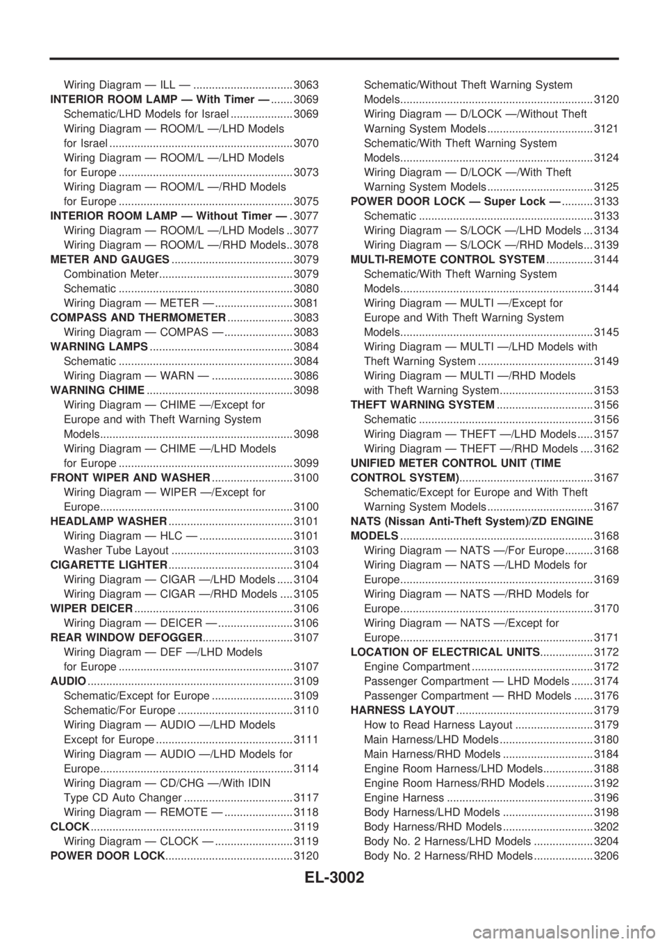
Wiring Diagram Ð ILL Ð ................................ 3063
INTERIOR ROOM LAMP Ð With Timer Ð....... 3069
Schematic/LHD Models for Israel .................... 3069
Wiring Diagram Ð ROOM/L Ð/LHD Models
for Israel ........................................................... 3070
Wiring Diagram Ð ROOM/L Ð/LHD Models
for Europe ........................................................ 3073
Wiring Diagram Ð ROOM/L Ð/RHD Models
for Europe ........................................................ 3075
INTERIOR ROOM LAMP Ð Without Timer Ð. 3077
Wiring Diagram Ð ROOM/L Ð/LHD Models .. 3077
Wiring Diagram Ð ROOM/L Ð/RHD Models.. 3078
METER AND GAUGES....................................... 3079
Combination Meter........................................... 3079
Schematic ........................................................ 3080
Wiring Diagram Ð METER Ð ......................... 3081
COMPASS AND THERMOMETER..................... 3083
Wiring Diagram Ð COMPAS Ð ...................... 3083
WARNING LAMPS.............................................. 3084
Schematic ........................................................ 3084
Wiring Diagram Ð WARN Ð .......................... 3086
WARNING CHIME............................................... 3098
Wiring Diagram Ð CHIME Ð/Except for
Europe and with Theft Warning System
Models.............................................................. 3098
Wiring Diagram Ð CHIME Ð/LHD Models
for Europe ........................................................ 3099
FRONT WIPER AND WASHER.......................... 3100
Wiring Diagram Ð WIPER Ð/Except for
Europe.............................................................. 3100
HEADLAMP WASHER........................................ 3101
Wiring Diagram Ð HLC Ð .............................. 3101
Washer Tube Layout ....................................... 3103
CIGARETTE LIGHTER........................................ 3104
Wiring Diagram Ð CIGAR Ð/LHD Models ..... 3104
Wiring Diagram Ð CIGAR Ð/RHD Models .... 3105
WIPER DEICER................................................... 3106
Wiring Diagram Ð DEICER Ð ........................ 3106
REAR WINDOW DEFOGGER............................. 3107
Wiring Diagram Ð DEF Ð/LHD Models
for Europe ........................................................ 3107
AUDIO.................................................................. 3109
Schematic/Except for Europe .......................... 3109
Schematic/For Europe ..................................... 3110
Wiring Diagram Ð AUDIO Ð/LHD Models
Except for Europe ............................................ 3111
Wiring Diagram Ð AUDIO Ð/LHD Models for
Europe.............................................................. 3114
Wiring Diagram Ð CD/CHG Ð/With IDIN
Type CD Auto Changer ................................... 3117
Wiring Diagram Ð REMOTE Ð ...................... 3118
CLOCK................................................................. 3119
Wiring Diagram Ð CLOCK Ð ......................... 3119
POWER DOOR LOCK......................................... 3120Schematic/Without Theft Warning System
Models.............................................................. 3120
Wiring Diagram Ð D/LOCK Ð/Without Theft
Warning System Models .................................. 3121
Schematic/With Theft Warning System
Models.............................................................. 3124
Wiring Diagram Ð D/LOCK Ð/With Theft
Warning System Models .................................. 3125
POWER DOOR LOCK Ð Super Lock Ð.......... 3133
Schematic ........................................................ 3133
Wiring Diagram Ð S/LOCK Ð/LHD Models ... 3134
Wiring Diagram Ð S/LOCK Ð/RHD Models... 3139
MULTI-REMOTE CONTROL SYSTEM............... 3144
Schematic/With Theft Warning System
Models.............................................................. 3144
Wiring Diagram Ð MULTI Ð/Except for
Europe and With Theft Warning System
Models.............................................................. 3145
Wiring Diagram Ð MULTI Ð/LHD Models with
Theft Warning System ..................................... 3149
Wiring Diagram Ð MULTI Ð/RHD Models
with Theft Warning System.............................. 3153
THEFT WARNING SYSTEM............................... 3156
Schematic ........................................................ 3156
Wiring Diagram Ð THEFT Ð/LHD Models ..... 3157
Wiring Diagram Ð THEFT Ð/RHD Models .... 3162
UNIFIED METER CONTROL UNIT (TIME
CONTROL SYSTEM)........................................... 3167
Schematic/Except for Europe and With Theft
Warning System Models .................................. 3167
NATS (Nissan Anti-Theft System)/ZD ENGINE
MODELS.............................................................. 3168
Wiring Diagram Ð NATS Ð/For Europe......... 3168
Wiring Diagram Ð NATS Ð/LHD Models for
Europe.............................................................. 3169
Wiring Diagram Ð NATS Ð/RHD Models for
Europe.............................................................. 3170
Wiring Diagram Ð NATS Ð/Except for
Europe.............................................................. 3171
LOCATION OF ELECTRICAL UNITS................. 3172
Engine Compartment ....................................... 3172
Passenger Compartment Ð LHD Models ....... 3174
Passenger Compartment Ð RHD Models ...... 3176
HARNESS LAYOUT............................................ 3179
How to Read Harness Layout ......................... 3179
Main Harness/LHD Models .............................. 3180
Main Harness/RHD Models ............................. 3184
Engine Room Harness/LHD Models................ 3188
Engine Room Harness/RHD Models ............... 3192
Engine Harness ............................................... 3196
Body Harness/LHD Models ............................. 3198
Body Harness/RHD Models ............................. 3202
Body No. 2 Harness/LHD Models ................... 3204
Body No. 2 Harness/RHD Models ................... 3206
EL-3002
Page 165 of 311

Wiring Diagram Ð CLOCK Ð
TEL828M
CLOCK
EL-3119
Page 166 of 311

Schematic/Without Theft Warning System
Models
TEL471M
POWER DOOR LOCK
EL-3120
Page 167 of 311

Wiring Diagram Ð D/LOCK Ð/Without Theft
Warning System Models
TEL839M
POWER DOOR LOCK
EL-3121
Page 168 of 311

TEL473M
POWER DOOR LOCK
Wiring Diagram Ð D/LOCK Ð/Without Theft
Warning System Models (Cont'd)
EL-3122