2002 NISSAN PATROL check engine
[x] Cancel search: check enginePage 33 of 311
Diagnostic Procedure
1 INSPECTION START
Do you have CONSULT-II?
Yes or No
YescGO TO 2.
NocGO TO 3.
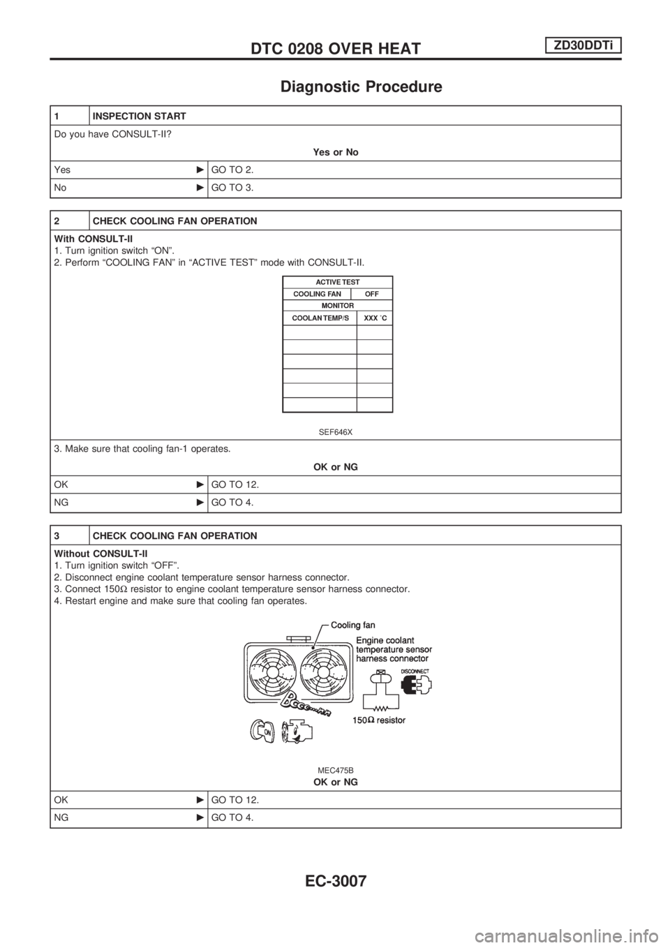
2 CHECK COOLING FAN OPERATION
With CONSULT-II
1. Turn ignition switch ªONº.
2. Perform ªCOOLING FANº in ªACTIVE TESTº mode with CONSULT-II.
SEF646X
3. Make sure that cooling fan-1 operates.
OK or NG
OKcGO TO 12.
NGcGO TO 4.
3 CHECK COOLING FAN OPERATION
Without CONSULT-II
1. Turn ignition switch ªOFFº.
2. Disconnect engine coolant temperature sensor harness connector.
3. Connect 150Wresistor to engine coolant temperature sensor harness connector.
4. Restart engine and make sure that cooling fan operates.
MEC475B
OK or NG
OKcGO TO 12.
NGcGO TO 4.
DTC 0208 OVER HEATZD30DDTi
EC-3007
Page 38 of 311
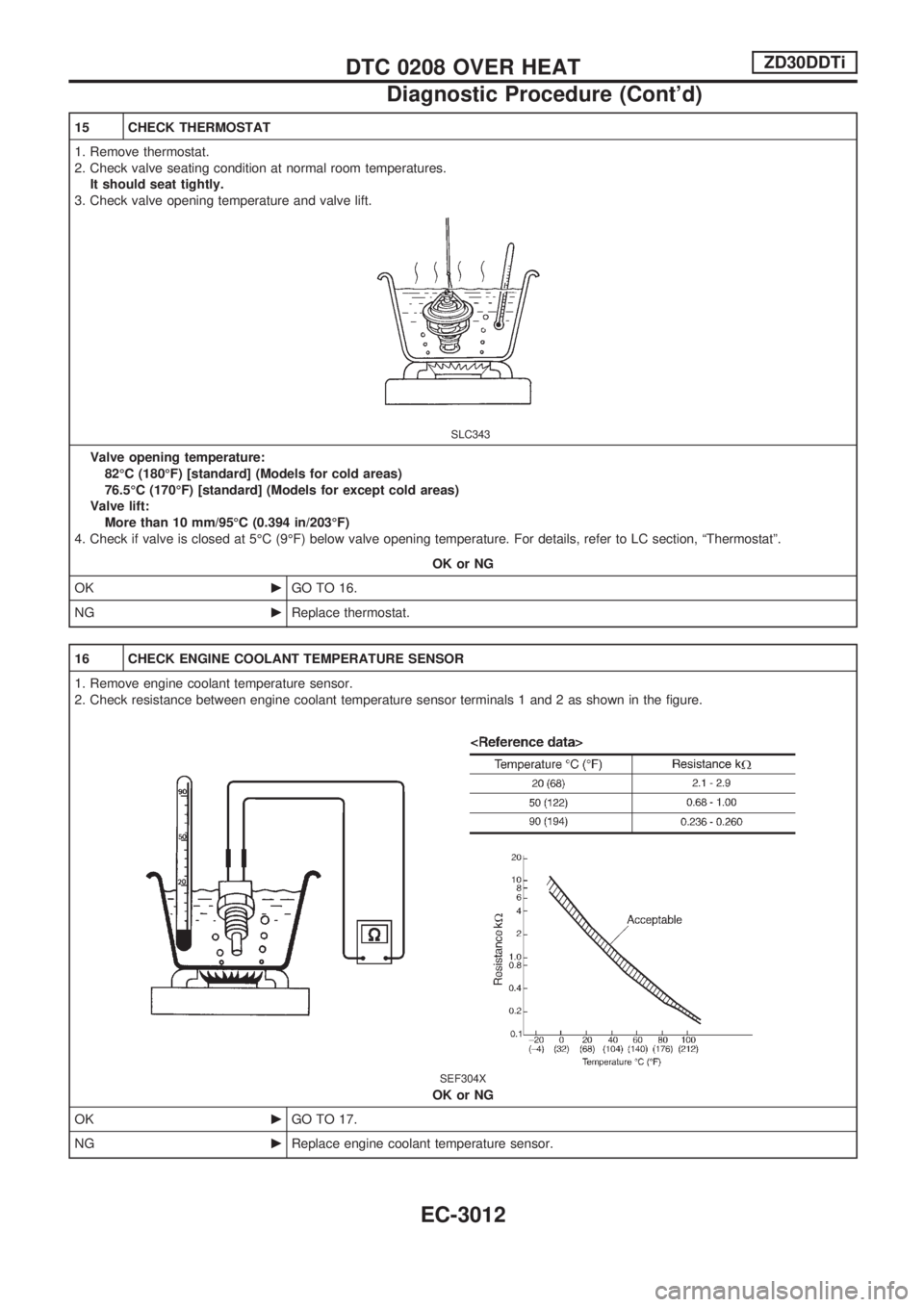
15 CHECK THERMOSTAT
1. Remove thermostat.
2. Check valve seating condition at normal room temperatures.
It should seat tightly.
3. Check valve opening temperature and valve lift.
SLC343
Valve opening temperature:
82ÉC (180ÉF) [standard] (Models for cold areas)
76.5ÉC (170ÉF) [standard] (Models for except cold areas)
Valve lift:
More than 10 mm/95ÉC (0.394 in/203ÉF)
4. Check if valve is closed at 5ÉC (9ÉF) below valve opening temperature. For details, refer to LC section, ªThermostatº.
OK or NG
OKcGO TO 16.
NGcReplace thermostat.
16 CHECK ENGINE COOLANT TEMPERATURE SENSOR
1. Remove engine coolant temperature sensor.
2. Check resistance between engine coolant temperature sensor terminals 1 and 2 as shown in the figure.
SEF304X
OK or NG
OKcGO TO 17.
NGcReplace engine coolant temperature sensor.
DTC 0208 OVER HEATZD30DDTi
Diagnostic Procedure (Cont'd)
EC-3012
Page 40 of 311
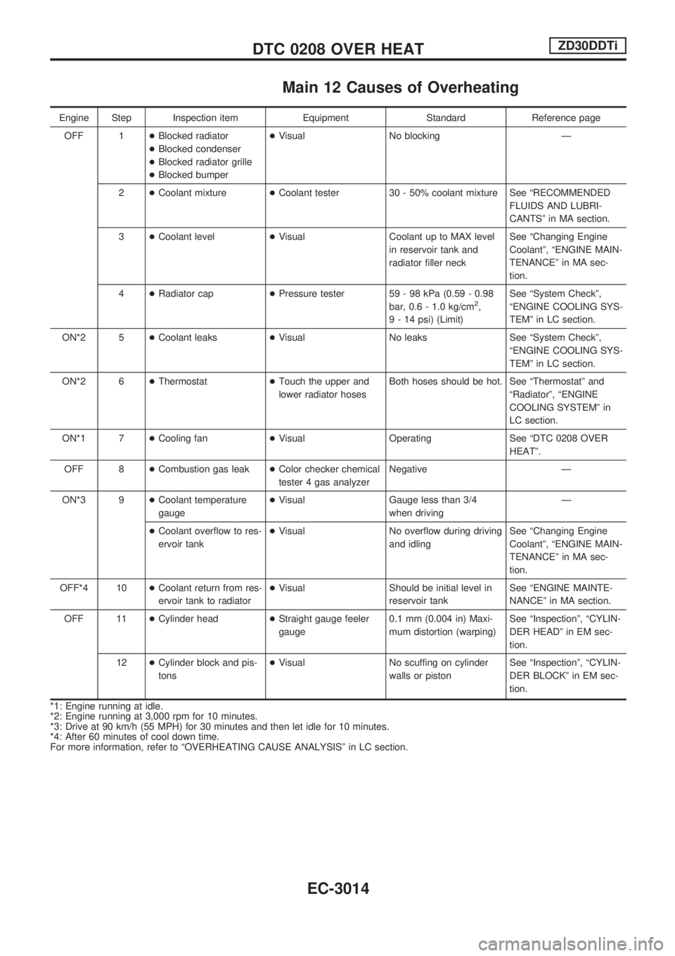
Main 12 Causes of Overheating
Engine Step Inspection item Equipment Standard Reference page
OFF 1+Blocked radiator
+Blocked condenser
+Blocked radiator grille
+Blocked bumper+Visual No blocking Ð
2+Coolant mixture+Coolant tester 30 - 50% coolant mixture See ªRECOMMENDED
FLUIDS AND LUBRI-
CANTSº in MA section.
3+Coolant level+Visual Coolant up to MAX level
in reservoir tank and
radiator filler neckSee ªChanging Engine
Coolantº, ªENGINE MAIN-
TENANCEº in MA sec-
tion.
4+Radiator cap+Pressure tester 59 - 98 kPa (0.59 - 0.98
bar, 0.6 - 1.0 kg/cm
2,
9 - 14 psi) (Limit)See ªSystem Checkº,
ªENGINE COOLING SYS-
TEMº in LC section.
ON*2 5+Coolant leaks+Visual No leaks See ªSystem Checkº,
ªENGINE COOLING SYS-
TEMº in LC section.
ON*2 6+Thermostat+Touch the upper and
lower radiator hosesBoth hoses should be hot. See ªThermostatº and
ªRadiatorº, ªENGINE
COOLING SYSTEMº in
LC section.
ON*1 7+Cooling fan+Visual Operating See ªDTC 0208 OVER
HEATº.
OFF 8+Combustion gas leak+Color checker chemical
tester 4 gas analyzerNegative Ð
ON*3 9+Coolant temperature
gauge+Visual Gauge less than 3/4
when drivingÐ
+Coolant overflow to res-
ervoir tank+Visual No overflow during driving
and idlingSee ªChanging Engine
Coolantº, ªENGINE MAIN-
TENANCEº in MA sec-
tion.
OFF*4 10+Coolant return from res-
ervoir tank to radiator+Visual Should be initial level in
reservoir tankSee ªENGINE MAINTE-
NANCEº in MA section.
OFF 11+Cylinder head+Straight gauge feeler
gauge0.1 mm (0.004 in) Maxi-
mum distortion (warping)See ªInspectionº, ªCYLIN-
DER HEADº in EM sec-
tion.
12+Cylinder block and pis-
tons+Visual No scuffing on cylinder
walls or pistonSee ªInspectionº, ªCYLIN-
DER BLOCKº in EM sec-
tion.
*1: Engine running at idle.
*2: Engine running at 3,000 rpm for 10 minutes.
*3: Drive at 90 km/h (55 MPH) for 30 minutes and then let idle for 10 minutes.
*4: After 60 minutes of cool down time.
For more information, refer to ªOVERHEATING CAUSE ANALYSISº in LC section.
DTC 0208 OVER HEATZD30DDTi
EC-3014
Page 47 of 311
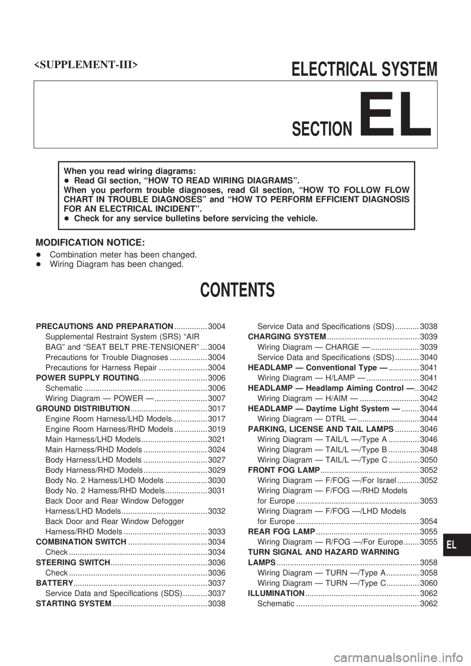
ELECTRICAL SYSTEM
SECTION
EL
When you read wiring diagrams:
+Read GI section, ªHOW TO READ WIRING DIAGRAMSº.
When you perform trouble diagnoses, read GI section, ªHOW TO FOLLOW FLOW
CHART IN TROUBLE DIAGNOSESº and ªHOW TO PERFORM EFFICIENT DIAGNOSIS
FOR AN ELECTRICAL INCIDENTº.
+Check for any service bulletins before servicing the vehicle.
MODIFICATION NOTICE:
+Combination meter has been changed.
+Wiring Diagram has been changed.
CONTENTS
PRECAUTIONS AND PREPARATION............... 3004
Supplemental Restraint System (SRS) ªAIR
BAGº and ªSEAT BELT PRE-TENSIONERº ... 3004
Precautions for Trouble Diagnoses ................. 3004
Precautions for Harness Repair ...................... 3004
POWER SUPPLY ROUTING............................... 3006
Schematic ........................................................ 3006
Wiring Diagram Ð POWER Ð ........................ 3007
GROUND DISTRIBUTION................................... 3017
Engine Room Harness/LHD Models................ 3017
Engine Room Harness/RHD Models ............... 3019
Main Harness/LHD Models .............................. 3021
Main Harness/RHD Models ............................. 3024
Body Harness/LHD Models ............................. 3027
Body Harness/RHD Models ............................. 3029
Body No. 2 Harness/LHD Models ................... 3030
Body No. 2 Harness/RHD Models ................... 3031
Back Door and Rear Window Defogger
Harness/LHD Models ....................................... 3032
Back Door and Rear Window Defogger
Harness/RHD Models ...................................... 3033
COMBINATION SWITCH.................................... 3034
Check ............................................................... 3034
STEERING SWITCH............................................ 3036
Check ............................................................... 3036
BATTERY............................................................. 3037
Service Data and Specifications (SDS) ........... 3037
STARTING SYSTEM........................................... 3038Service Data and Specifications (SDS) ........... 3038
CHARGING SYSTEM.......................................... 3039
Wiring Diagram Ð CHARGE Ð ...................... 3039
Service Data and Specifications (SDS) ........... 3040
HEADLAMP Ð Conventional Type Ð.............. 3041
Wiring Diagram Ð H/LAMP Ð ........................ 3041
HEADLAMP Ð Headlamp Aiming Control Ð.. 3042
Wiring Diagram Ð H/AIM Ð ........................... 3042
HEADLAMP Ð Daytime Light System Ð........ 3044
Wiring Diagram Ð DTRL Ð ............................ 3044
PARKING, LICENSE AND TAIL LAMPS........... 3046
Wiring Diagram Ð TAIL/L Ð/Type A .............. 3046
Wiring Diagram Ð TAIL/L Ð/Type B .............. 3048
Wiring Diagram Ð TAIL/L Ð/Type C .............. 3050
FRONT FOG LAMP............................................. 3052
Wiring Diagram Ð F/FOG Ð/For Israel .......... 3052
Wiring Diagram Ð F/FOG Ð/RHD Models
for Europe ........................................................ 3053
Wiring Diagram Ð F/FOG Ð/LHD Models
for Europe ........................................................ 3054
REAR FOG LAMP............................................... 3055
Wiring Diagram Ð R/FOG Ð/For Europe ....... 3055
TURN SIGNAL AND HAZARD WARNING
LAMPS................................................................. 3058
Wiring Diagram Ð TURN Ð/Type A ............... 3058
Wiring Diagram Ð TURN Ð/Type C............... 3060
ILLUMINATION.................................................... 3062
Schematic ........................................................ 3062
EL
Page 270 of 311
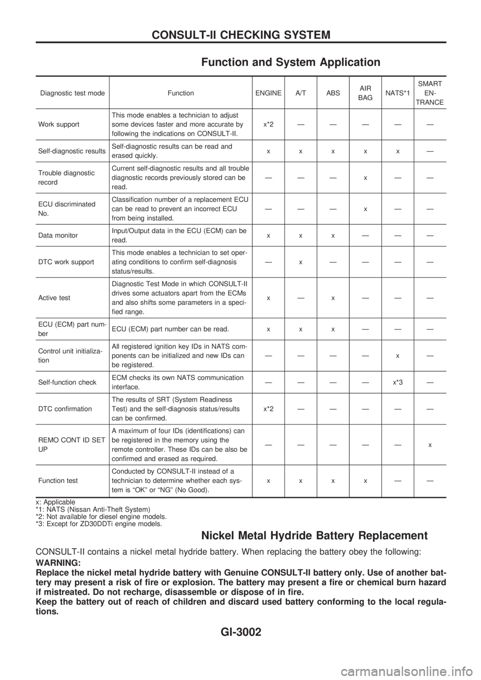
Function and System Application
Diagnostic test mode Function ENGINE A/T ABSAIR
BAGNATS*1SMART
EN-
TRANCE
Work supportThis mode enables a technician to adjust
some devices faster and more accurate by
following the indications on CONSULT-II.x*2ÐÐÐÐÐ
Self-diagnostic resultsSelf-diagnostic results can be read and
erased quickly.xxxxxÐ
Trouble diagnostic
recordCurrent self-diagnostic results and all trouble
diagnostic records previously stored can be
read.ÐÐÐxÐÐ
ECU discriminated
No.Classification number of a replacement ECU
can be read to prevent an incorrect ECU
from being installed.ÐÐÐxÐÐ
Data monitorInput/Output data in the ECU (ECM) can be
read.xxxÐÐÐ
DTC work supportThis mode enables a technician to set oper-
ating conditions to confirm self-diagnosis
status/results.Ð x ÐÐÐÐ
Active testDiagnostic Test Mode in which CONSULT-II
drives some actuators apart from the ECMs
and also shifts some parameters in a speci-
fied range.xÐxÐÐÐ
ECU (ECM) part num-
berECU (ECM) part number can be read. x x x Ð Ð Ð
Control unit initializa-
tionAll registered ignition key IDs in NATS com-
ponents can be initialized and new IDs can
be registered.ÐÐÐÐ x Ð
Self-function checkECM checks its own NATS communication
interface.ÐÐÐÐx*3Ð
DTC confirmationThe results of SRT (System Readiness
Test) and the self-diagnosis status/results
can be confirmed.x*2ÐÐÐÐÐ
REMO CONT ID SET
UPA maximum of four IDs (identifications) can
be registered in the memory using the
remote controller. These IDs can be also be
confirmed and erased as required.ÐÐÐÐÐ x
Function testConducted by CONSULT-II instead of a
technician to determine whether each sys-
tem is ªOKº or ªNGº (No Good).xxxxÐÐ
x: Applicable
*1: NATS (Nissan Anti-Theft System)
*2: Not available for diesel engine models.
*3: Except for ZD30DDTi engine models.
Nickel Metal Hydride Battery Replacement
CONSULT-II contains a nickel metal hydride battery. When replacing the battery obey the following:
WARNING:
Replace the nickel metal hydride battery with Genuine CONSULT-II battery only. Use of another bat-
tery may present a risk of fire or explosion. The battery may present a fire or chemical burn hazard
if mistreated. Do not recharge, disassemble or dispose of in fire.
Keep the battery out of reach of children and discard used battery conforming to the local regula-
tions.
CONSULT-II CHECKING SYSTEM
GI-3002