2002 NISSAN PATROL color
[x] Cancel search: colorPage 40 of 311
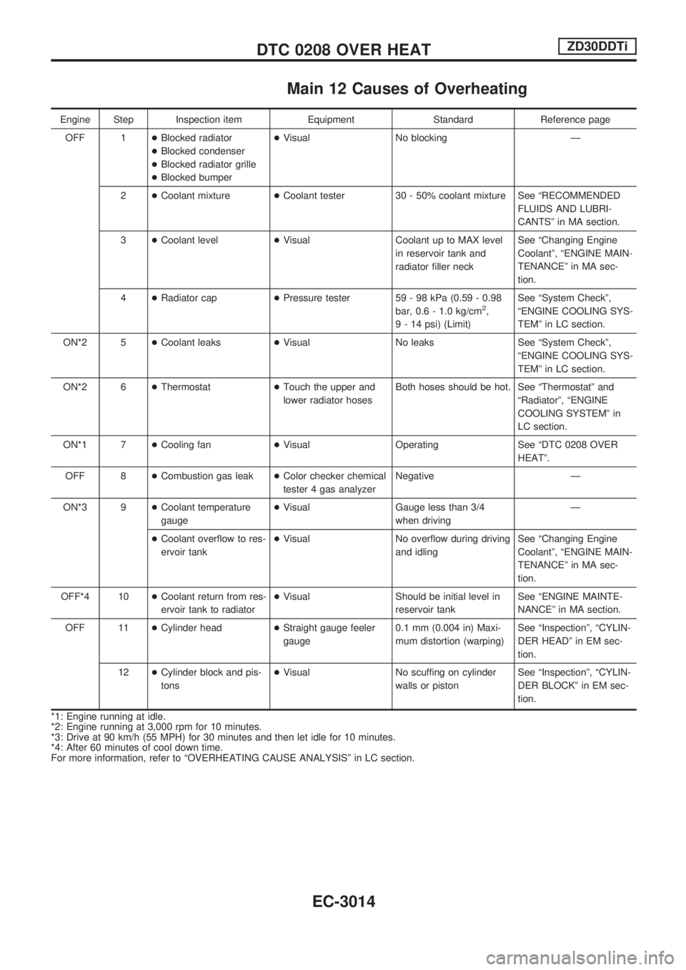
Main 12 Causes of Overheating
Engine Step Inspection item Equipment Standard Reference page
OFF 1+Blocked radiator
+Blocked condenser
+Blocked radiator grille
+Blocked bumper+Visual No blocking Ð
2+Coolant mixture+Coolant tester 30 - 50% coolant mixture See ªRECOMMENDED
FLUIDS AND LUBRI-
CANTSº in MA section.
3+Coolant level+Visual Coolant up to MAX level
in reservoir tank and
radiator filler neckSee ªChanging Engine
Coolantº, ªENGINE MAIN-
TENANCEº in MA sec-
tion.
4+Radiator cap+Pressure tester 59 - 98 kPa (0.59 - 0.98
bar, 0.6 - 1.0 kg/cm
2,
9 - 14 psi) (Limit)See ªSystem Checkº,
ªENGINE COOLING SYS-
TEMº in LC section.
ON*2 5+Coolant leaks+Visual No leaks See ªSystem Checkº,
ªENGINE COOLING SYS-
TEMº in LC section.
ON*2 6+Thermostat+Touch the upper and
lower radiator hosesBoth hoses should be hot. See ªThermostatº and
ªRadiatorº, ªENGINE
COOLING SYSTEMº in
LC section.
ON*1 7+Cooling fan+Visual Operating See ªDTC 0208 OVER
HEATº.
OFF 8+Combustion gas leak+Color checker chemical
tester 4 gas analyzerNegative Ð
ON*3 9+Coolant temperature
gauge+Visual Gauge less than 3/4
when drivingÐ
+Coolant overflow to res-
ervoir tank+Visual No overflow during driving
and idlingSee ªChanging Engine
Coolantº, ªENGINE MAIN-
TENANCEº in MA sec-
tion.
OFF*4 10+Coolant return from res-
ervoir tank to radiator+Visual Should be initial level in
reservoir tankSee ªENGINE MAINTE-
NANCEº in MA section.
OFF 11+Cylinder head+Straight gauge feeler
gauge0.1 mm (0.004 in) Maxi-
mum distortion (warping)See ªInspectionº, ªCYLIN-
DER HEADº in EM sec-
tion.
12+Cylinder block and pis-
tons+Visual No scuffing on cylinder
walls or pistonSee ªInspectionº, ªCYLIN-
DER BLOCKº in EM sec-
tion.
*1: Engine running at idle.
*2: Engine running at 3,000 rpm for 10 minutes.
*3: Drive at 90 km/h (55 MPH) for 30 minutes and then let idle for 10 minutes.
*4: After 60 minutes of cool down time.
For more information, refer to ªOVERHEATING CAUSE ANALYSISº in LC section.
DTC 0208 OVER HEATZD30DDTi
EC-3014
Page 225 of 311
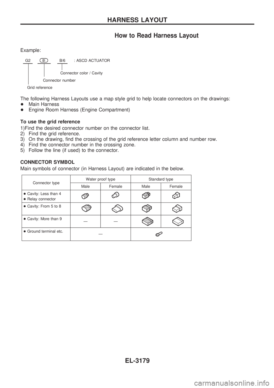
How to Read Harness Layout
Example:
G2E1B/6: ASCD ACTUATOR
Connector color / Cavity
Connector number
Grid reference
The following Harness Layouts use a map style grid to help locate connectors on the drawings:
+Main Harness
+Engine Room Harness (Engine Compartment)
To use the grid reference
1)Find the desired connector number on the connector list.
2) Find the grid reference.
3) On the drawing, find the crossing of the grid reference letter column and number row.
4) Find the connector number in the crossing zone.
5) Follow the line (if used) to the connector.
CONNECTOR SYMBOL
Main symbols of connector (in Harness Layout) are indicated in the below.
Connector typeWater proof type Standard type
Male Female Male Female
+Cavity: Less than 4
+Relay connector
+Cavity: From 5 to 8
+Cavity: More than 9
ÐÐ
+Ground terminal etc.
Ð
HARNESS LAYOUT
EL-3179
Page 260 of 311
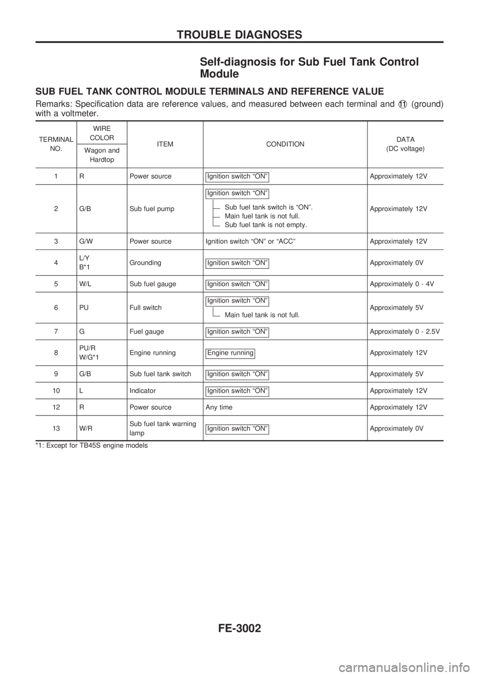
Self-diagnosis for Sub Fuel Tank Control
Module
SUB FUEL TANK CONTROL MODULE TERMINALS AND REFERENCE VALUE
Remarks: Specification data are reference values, and measured between each terminal andV11(ground)
with a voltmeter.
TERMINAL
NO.WIRE
COLOR
ITEM CONDITIONDATA
(DC voltage)
Wagon and
Hardtop
1 R Power source Ignition switch ªONº
Approximately 12V
2 G/B Sub fuel pumpIgnition switch ªONº
Sub fuel tank switch is ªONº.
Main fuel tank is not full.
Sub fuel tank is not empty.Approximately 12V
3 G/W Power source Ignition switch ªONº or ªACCº Approximately 12V
4L/Y
B*1Grounding Ignition switch ªONº
Approximately 0V
5 W/L Sub fuel gauge Ignition switch ªONº
Approximately0-4V
6 PU Full switchIgnition switch ªONº
Main fuel tank is not full.Approximately 5V
7 G Fuel gauge Ignition switch ªONº
Approximately 0 - 2.5V
8PU/R
W/G*1Engine running Engine running
Approximately 12V
9 G/B Sub fuel tank switch Ignition switch ªONº
Approximately 5V
10 L Indicator Ignition switch ªONº
Approximately 12V
12 R Power source Any time Approximately 12V
13 W/RSub fuel tank warning
lampIgnition switch ªONº
Approximately 0V
*1: Except for TB45S engine models
TROUBLE DIAGNOSES
FE-3002
Page 283 of 311
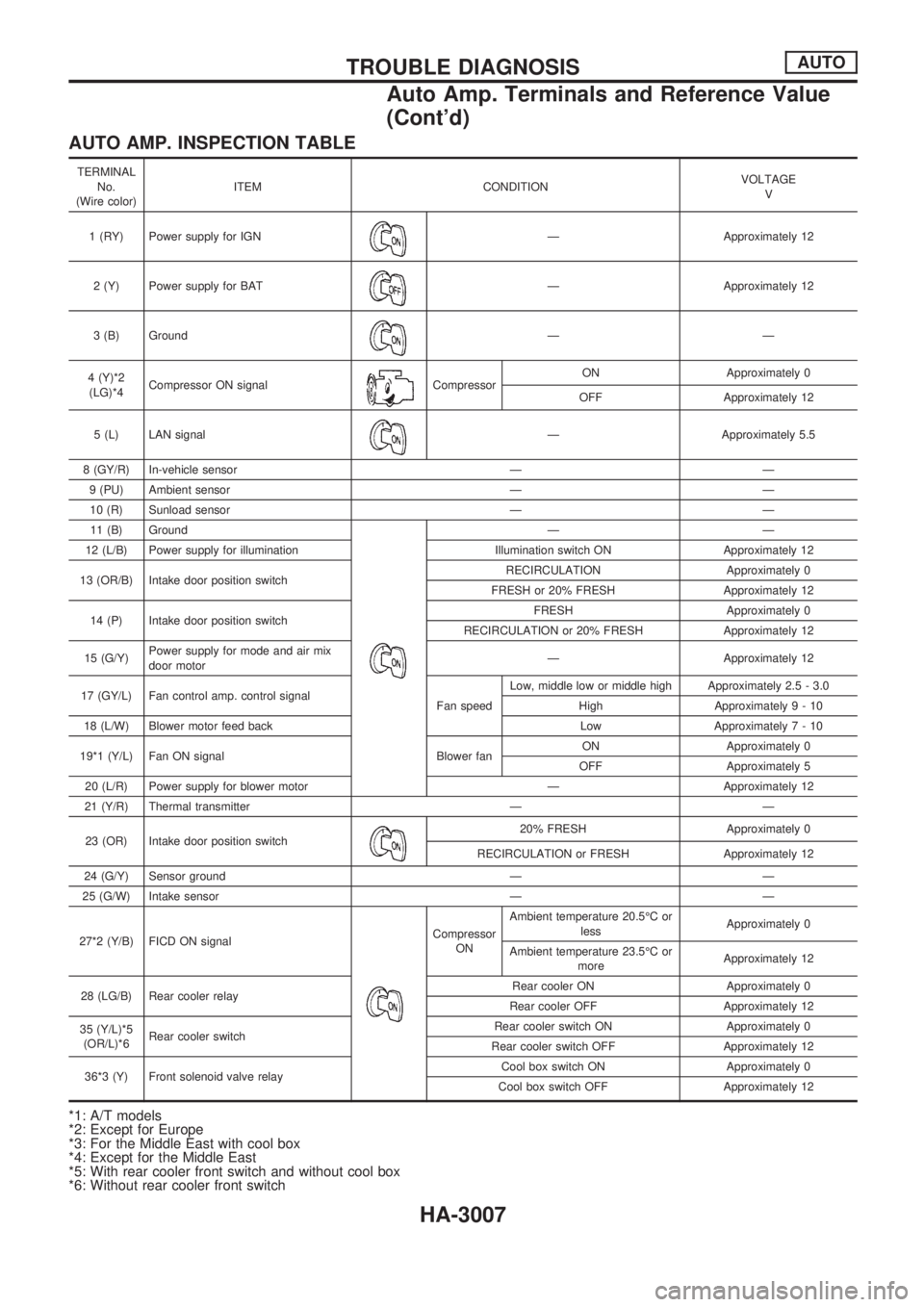
AUTO AMP. INSPECTION TABLE
TERMINAL
No.
(Wire color)ITEM CONDITIONVOLTAGE
V
1 (RY) Power supply for IGN
Ð Approximately 12
2 (Y) Power supply for BAT
Ð Approximately 12
3 (B) Ground
ÐÐ
4 (Y)*2
(LG)*4Compressor ON signal
CompressorON Approximately 0
OFF Approximately 12
5 (L) LAN signal
Ð Approximately 5.5
8 (GY/R) In-vehicle sensor Ð Ð
9 (PU) Ambient sensor Ð Ð
10 (R) Sunload sensor Ð Ð
11 (B) Ground
ÐÐ
12 (L/B) Power supply for illumination Illumination switch ON Approximately 12
13 (OR/B) Intake door position switchRECIRCULATION Approximately 0
FRESH or 20% FRESH Approximately 12
14 (P) Intake door position switchFRESH Approximately 0
RECIRCULATION or 20% FRESH Approximately 12
15 (G/Y)Power supply for mode and air mix
door motorÐ Approximately 12
17 (GY/L) Fan control amp. control signal
Fan speedLow, middle low or middle high Approximately 2.5 - 3.0
High Approximately9-10
18 (L/W) Blower motor feed back Low Approximately7-10
19*1 (Y/L) Fan ON signal Blower fanON Approximately 0
OFF Approximately 5
20 (L/R) Power supply for blower motor Ð Approximately 12
21 (Y/R) Thermal transmitter Ð Ð
23 (OR) Intake door position switch
20% FRESH Approximately 0
RECIRCULATION or FRESH Approximately 12
24 (G/Y) Sensor ground Ð Ð
25 (G/W) Intake sensor Ð Ð
27*2 (Y/B) FICD ON signal
Compressor
ONAmbient temperature 20.5ÉC or
lessApproximately 0
Ambient temperature 23.5ÉC or
moreApproximately 12
28 (LG/B) Rear cooler relayRear cooler ON Approximately 0
Rear cooler OFF Approximately 12
35 (Y/L)*5
(OR/L)*6Rear cooler switchRear cooler switch ON Approximately 0
Rear cooler switch OFF Approximately 12
36*3 (Y) Front solenoid valve relayCool box switch ON Approximately 0
Cool box switch OFF Approximately 12
*1: A/T models
*2: Except for Europe
*3: For the Middle East with cool box
*4: Except for the Middle East
*5: With rear cooler front switch and without cool box
*6: Without rear cooler front switch
TROUBLE DIAGNOSISAUTO
Auto Amp. Terminals and Reference Value
(Cont'd)
HA-3007
Page 293 of 311
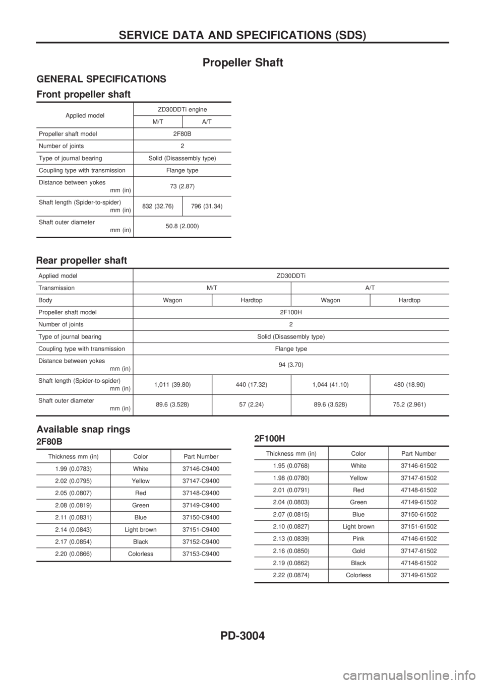
Propeller Shaft
GENERAL SPECIFICATIONS
Front propeller shaft
Applied modelZD30DDTi engine
M/T A/T
Propeller shaft model 2F80B
Number of joints 2
Type of journal bearing Solid (Disassembly type)
Coupling type with transmission Flange type
Distance between yokes
mm (in)73 (2.87)
Shaft length (Spider-to-spider)
mm (in)832 (32.76) 796 (31.34)
Shaft outer diameter
mm (in)50.8 (2.000)
Rear propeller shaft
Applied modelZD30DDTi
Transmission M/T A/T
Body Wagon Hardtop Wagon Hardtop
Propeller shaft model 2F100H
Number of joints2
Type of journal bearing Solid (Disassembly type)
Coupling type with transmission Flange type
Distance between yokes
mm (in)94 (3.70)
Shaft length (Spider-to-spider)
mm (in)1,011 (39.80) 440 (17.32) 1,044 (41.10) 480 (18.90)
Shaft outer diameter
mm (in)89.6 (3.528) 57 (2.24) 89.6 (3.528) 75.2 (2.961)
Available snap rings
2F80B
Thickness mm (in) Color Part Number
1.99 (0.0783) White 37146-C9400
2.02 (0.0795) Yellow 37147-C9400
2.05 (0.0807) Red 37148-C9400
2.08 (0.0819) Green 37149-C9400
2.11 (0.0831) Blue 37150-C9400
2.14 (0.0843) Light brown 37151-C9400
2.17 (0.0854) Black 37152-C9400
2.20 (0.0866) Colorless 37153-C9400
2F100H
Thickness mm (in) Color Part Number
1.95 (0.0768) White 37146-61502
1.98 (0.0780) Yellow 37147-61502
2.01 (0.0791) Red 47148-61502
2.04 (0.0803) Green 47149-61502
2.07 (0.0815) Blue 37150-61502
2.10 (0.0827) Light brown 37151-61502
2.13 (0.0839) Pink 47146-61502
2.16 (0.0850) Gold 37147-61502
2.19 (0.0862) Black 47148-61502
2.22 (0.0874) Colorless 37149-61502
SERVICE DATA AND SPECIFICATIONS (SDS)
PD-3004