Page 1 of 311
Edition: October 2002
Release: November 2002 (01)
Publication No.: SM2E-Y61CE0E
Reference No.: 7711346700GENERAL INFORMATIONGI
MAINTENANCEMA
ENGINE MECHANICALEM
ENGINE LUBRICATION &
COOLING SYSTEMSLC
ENGINE CONTROL SYSTEMEC
ACCELERATOR CONTROL,
FUEL & EXHAUST SYSTEMFE
CLUTCHCL
MANUAL TRANSMISSIONMT
AUTOMATIC TRANSMISSIONAT
TRANSFERTF
PROPELLER SHAFT &
DIFFERENTIAL CARRIERPD
FRONT AXLE & FRONT SUSPENSIONFA
REAR AXLE & REAR SUSPENSIONRA
BRAKE SYSTEMBR
STEERING SYSTEMST
RESTRAINT SYSTEMRS
BODY & TRIMBT
HEATER & AIR CONDITIONERHA
ELECTRICAL SYSTEMEL
ALPHABETICAL INDEXIDX
PATROL GR
MODEL Y61 SERIES
NISSAN EUROPE S.A.S.
2002 NISSAN EUROPE S.A.S.
Produced in The Netherlands
Not to be reproduced in whole or in part
without the prior written permission of
Nissan Europe S.A.S., Paris, France.
QUICK REFERENCE INDEX
Page 33 of 311
Diagnostic Procedure
1 INSPECTION START
Do you have CONSULT-II?
Yes or No
YescGO TO 2.
NocGO TO 3.
2 CHECK COOLING FAN OPERATION
With CONSULT-II
1. Turn ignition switch ªONº.
2. Perform ªCOOLING FANº in ªACTIVE TESTº mode with CONSULT-II.
SEF646X
3. Make sure that cooling fan-1 operates.
OK or NG
OKcGO TO 12.
NGcGO TO 4.
3 CHECK COOLING FAN OPERATION
Without CONSULT-II
1. Turn ignition switch ªOFFº.
2. Disconnect engine coolant temperature sensor harness connector.
3. Connect 150Wresistor to engine coolant temperature sensor harness connector.
4. Restart engine and make sure that cooling fan operates.
MEC475B
OK or NG
OKcGO TO 12.
NGcGO TO 4.
DTC 0208 OVER HEATZD30DDTi
EC-3007
Page 34 of 311
4 CHECK COOLING FAN POWER SUPPLY CIRCUIT
1. Turn ignition switch ªOFFº.
2. Disconnect cooling fan relay-1.
SEF690V
3. Turn ignition switch ªONº.
4. Check voltage between cooling fan relay-1 terminals 1, 3, 6 and ground with CONSULT-II or tester.
SEC533D
OK or NG
OKcGO TO 6.
NGcGO TO 5.
5 DETECT MALFUNCTIONING PART
Check the following.
+Fuse block (J/B) connector E112
+10A fuse or 20A fuse
+40A fusible links
+Harness for open or short between cooling fan relay-1 and fuse
+Harness for open or short between cooling fan relay-1 and battery
cRepair open circuit or short to ground or short to power in harness or connectors.
DTC 0208 OVER HEATZD30DDTi
Diagnostic Procedure (Cont'd)
EC-3008
Page 35 of 311

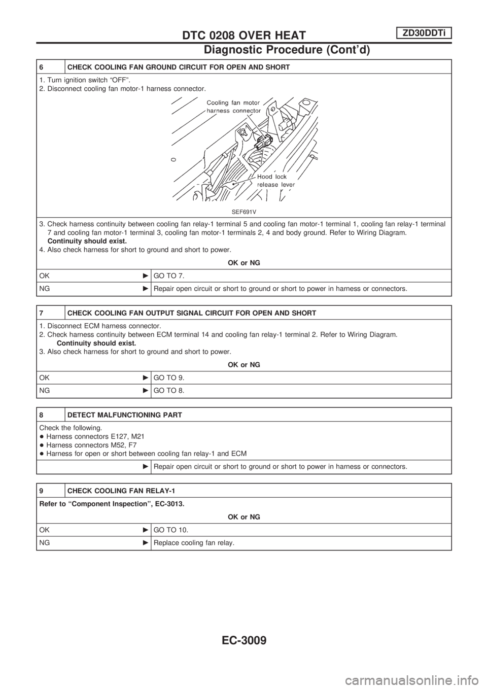
6 CHECK COOLING FAN GROUND CIRCUIT FOR OPEN AND SHORT
1. Turn ignition switch ªOFFº.
2. Disconnect cooling fan motor-1 harness connector.
SEF691V
3. Check harness continuity between cooling fan relay-1 terminal 5 and cooling fan motor-1 terminal 1, cooling fan relay-1 terminal
7 and cooling fan motor-1 terminal 3, cooling fan motor-1 terminals 2, 4 and body ground. Refer to Wiring Diagram.
Continuity should exist.
4. Also check harness for short to ground and short to power.
OK or NG
OKcGO TO 7.
NGcRepair open circuit or short to ground or short to power in harness or connectors.
7 CHECK COOLING FAN OUTPUT SIGNAL CIRCUIT FOR OPEN AND SHORT
1. Disconnect ECM harness connector.
2. Check harness continuity between ECM terminal 14 and cooling fan relay-1 terminal 2. Refer to Wiring Diagram.
Continuity should exist.
3. Also check harness for short to ground and short to power.
OK or NG
OKcGO TO 9.
NGcGO TO 8.
8 DETECT MALFUNCTIONING PART
Check the following.
+Harness connectors E127, M21
+Harness connectors M52, F7
+Harness for open or short between cooling fan relay-1 and ECM
cRepair open circuit or short to ground or short to power in harness or connectors.
9 CHECK COOLING FAN RELAY-1
Refer to ªComponent Inspectionº, EC-3013.
OK or NG
OKcGO TO 10.
NGcReplace cooling fan relay.
DTC 0208 OVER HEATZD30DDTi
Diagnostic Procedure (Cont'd)
EC-3009
Page 36 of 311
10 CHECK COOLING FAN MOTOR-1
Supply battery voltage between the following terminals and check operation.
SEF645V
MTBL1304
OK or NG
OKcGO TO 11.
NGcReplace cooling fan motor.
11 CHECK INTERMITTENT INCIDENT
Perform ªTROUBLE DIAGNOSIS FOR INTERMITTENT INCIDENTº.
cINSPECTION END
12 CHECK COOLING SYSTEM FOR LEAK
Apply pressure to the cooling system with a tester, and check if the pressure drops.
Testing pressure: 98 kPa (0.98 bar, 1.0 kg/cm
2, 14 psi)
CAUTION:
Higher than the specified pressure may cause radiator damage.
SLC754A
Pressure should not drop.
OK or NG
OKcGO TO 14.
NGcGO TO 13.
DTC 0208 OVER HEATZD30DDTi
Diagnostic Procedure (Cont'd)
EC-3010
Page 39 of 311
17 CHECK MAIN 12 CAUSES
If the cause cannot be isolated, go to ªMAIN 12 CAUSES OF OVERHEATINGº, EC-3014.
cINSPECTION END
Component Inspection
COOLING FAN RELAY-1
Check continuity between terminalsV3andV5,V6andV7.
Conditions Continuity
12V direct current supply between
terminals 1 and 2Yes
No current supply No
If NG, replace relay.SEC202B
DTC 0208 OVER HEATZD30DDTi
Diagnostic Procedure (Cont'd)
EC-3013
Page 40 of 311

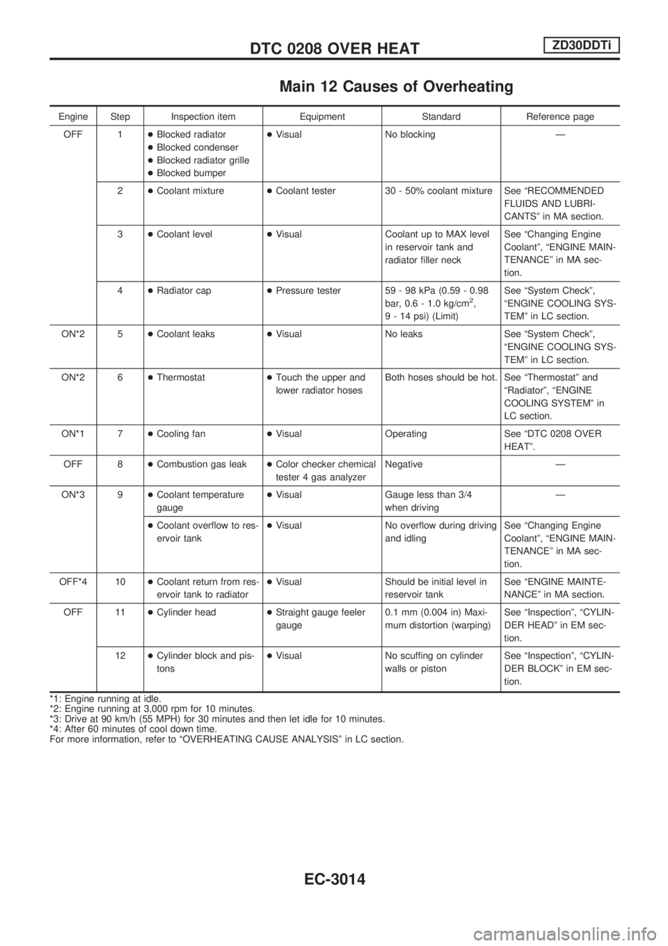
Main 12 Causes of Overheating
Engine Step Inspection item Equipment Standard Reference page
OFF 1+Blocked radiator
+Blocked condenser
+Blocked radiator grille
+Blocked bumper+Visual No blocking Ð
2+Coolant mixture+Coolant tester 30 - 50% coolant mixture See ªRECOMMENDED
FLUIDS AND LUBRI-
CANTSº in MA section.
3+Coolant level+Visual Coolant up to MAX level
in reservoir tank and
radiator filler neckSee ªChanging Engine
Coolantº, ªENGINE MAIN-
TENANCEº in MA sec-
tion.
4+Radiator cap+Pressure tester 59 - 98 kPa (0.59 - 0.98
bar, 0.6 - 1.0 kg/cm
2,
9 - 14 psi) (Limit)See ªSystem Checkº,
ªENGINE COOLING SYS-
TEMº in LC section.
ON*2 5+Coolant leaks+Visual No leaks See ªSystem Checkº,
ªENGINE COOLING SYS-
TEMº in LC section.
ON*2 6+Thermostat+Touch the upper and
lower radiator hosesBoth hoses should be hot. See ªThermostatº and
ªRadiatorº, ªENGINE
COOLING SYSTEMº in
LC section.
ON*1 7+Cooling fan+Visual Operating See ªDTC 0208 OVER
HEATº.
OFF 8+Combustion gas leak+Color checker chemical
tester 4 gas analyzerNegative Ð
ON*3 9+Coolant temperature
gauge+Visual Gauge less than 3/4
when drivingÐ
+Coolant overflow to res-
ervoir tank+Visual No overflow during driving
and idlingSee ªChanging Engine
Coolantº, ªENGINE MAIN-
TENANCEº in MA sec-
tion.
OFF*4 10+Coolant return from res-
ervoir tank to radiator+Visual Should be initial level in
reservoir tankSee ªENGINE MAINTE-
NANCEº in MA section.
OFF 11+Cylinder head+Straight gauge feeler
gauge0.1 mm (0.004 in) Maxi-
mum distortion (warping)See ªInspectionº, ªCYLIN-
DER HEADº in EM sec-
tion.
12+Cylinder block and pis-
tons+Visual No scuffing on cylinder
walls or pistonSee ªInspectionº, ªCYLIN-
DER BLOCKº in EM sec-
tion.
*1: Engine running at idle.
*2: Engine running at 3,000 rpm for 10 minutes.
*3: Drive at 90 km/h (55 MPH) for 30 minutes and then let idle for 10 minutes.
*4: After 60 minutes of cool down time.
For more information, refer to ªOVERHEATING CAUSE ANALYSISº in LC section.
DTC 0208 OVER HEATZD30DDTi
EC-3014
Page 256 of 311

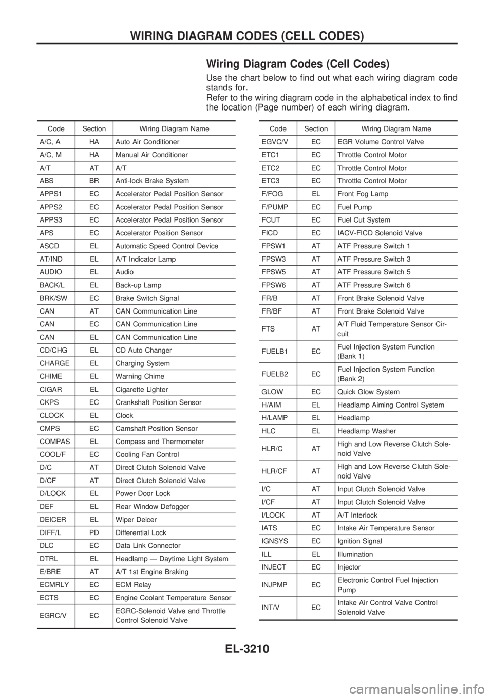
Wiring Diagram Codes (Cell Codes)
Use the chart below to find out what each wiring diagram code
stands for.
Refer to the wiring diagram code in the alphabetical index to find
the location (Page number) of each wiring diagram.
Code Section Wiring Diagram Name
A/C, A HA Auto Air Conditioner
A/C, M HA Manual Air Conditioner
A/T AT A/T
ABS BR Anti-lock Brake System
APPS1 EC Accelerator Pedal Position Sensor
APPS2 EC Accelerator Pedal Position Sensor
APPS3 EC Accelerator Pedal Position Sensor
APS EC Accelerator Position Sensor
ASCD EL Automatic Speed Control Device
AT/IND EL A/T Indicator Lamp
AUDIO EL Audio
BACK/L EL Back-up Lamp
BRK/SW EC Brake Switch Signal
CAN AT CAN Communication Line
CAN EC CAN Communication Line
CAN EL CAN Communication Line
CD/CHG EL CD Auto Changer
CHARGE EL Charging System
CHIME EL Warning Chime
CIGAR EL Cigarette Lighter
CKPS EC Crankshaft Position Sensor
CLOCK EL Clock
CMPS EC Camshaft Position Sensor
COMPAS EL Compass and Thermometer
COOL/F EC Cooling Fan Control
D/C AT Direct Clutch Solenoid Valve
D/CF AT Direct Clutch Solenoid Valve
D/LOCK EL Power Door Lock
DEF EL Rear Window Defogger
DEICER EL Wiper Deicer
DIFF/L PD Differential Lock
DLC EC Data Link Connector
DTRL EL Headlamp Ð Daytime Light System
E/BRE AT A/T 1st Engine Braking
ECMRLY EC ECM Relay
ECTS EC Engine Coolant Temperature Sensor
EGRC/V ECEGRC-Solenoid Valve and Throttle
Control Solenoid ValveCode Section Wiring Diagram Name
EGVC/V EC EGR Volume Control Valve
ETC1 EC Throttle Control Motor
ETC2 EC Throttle Control Motor
ETC3 EC Throttle Control Motor
F/FOG EL Front Fog Lamp
F/PUMP EC Fuel Pump
FCUT EC Fuel Cut System
FICD EC IACV-FICD Solenoid Valve
FPSW1 AT ATF Pressure Switch 1
FPSW3 AT ATF Pressure Switch 3
FPSW5 AT ATF Pressure Switch 5
FPSW6 AT ATF Pressure Switch 6
FR/B AT Front Brake Solenoid Valve
FR/BF AT Front Brake Solenoid Valve
FTS ATA/T Fluid Temperature Sensor Cir-
cuit
FUELB1 ECFuel Injection System Function
(Bank 1)
FUELB2 ECFuel Injection System Function
(Bank 2)
GLOW EC Quick Glow System
H/AIM EL Headlamp Aiming Control System
H/LAMP EL Headlamp
HLC EL Headlamp Washer
HLR/C ATHigh and Low Reverse Clutch Sole-
noid Valve
HLR/CF ATHigh and Low Reverse Clutch Sole-
noid Valve
I/C AT Input Clutch Solenoid Valve
I/CF AT Input Clutch Solenoid Valve
I/LOCK AT A/T Interlock
IATS EC Intake Air Temperature Sensor
IGNSYS EC Ignition Signal
ILL EL Illumination
INJECT EC Injector
INJPMP ECElectronic Control Fuel Injection
Pump
INT/V ECIntake Air Control Valve Control
Solenoid Valve
WIRING DIAGRAM CODES (CELL CODES)
EL-3210