2002 NISSAN PATROL charging
[x] Cancel search: chargingPage 47 of 311

ELECTRICAL SYSTEM
SECTION
EL
When you read wiring diagrams:
+Read GI section, ªHOW TO READ WIRING DIAGRAMSº.
When you perform trouble diagnoses, read GI section, ªHOW TO FOLLOW FLOW
CHART IN TROUBLE DIAGNOSESº and ªHOW TO PERFORM EFFICIENT DIAGNOSIS
FOR AN ELECTRICAL INCIDENTº.
+Check for any service bulletins before servicing the vehicle.
MODIFICATION NOTICE:
+Combination meter has been changed.
+Wiring Diagram has been changed.
CONTENTS
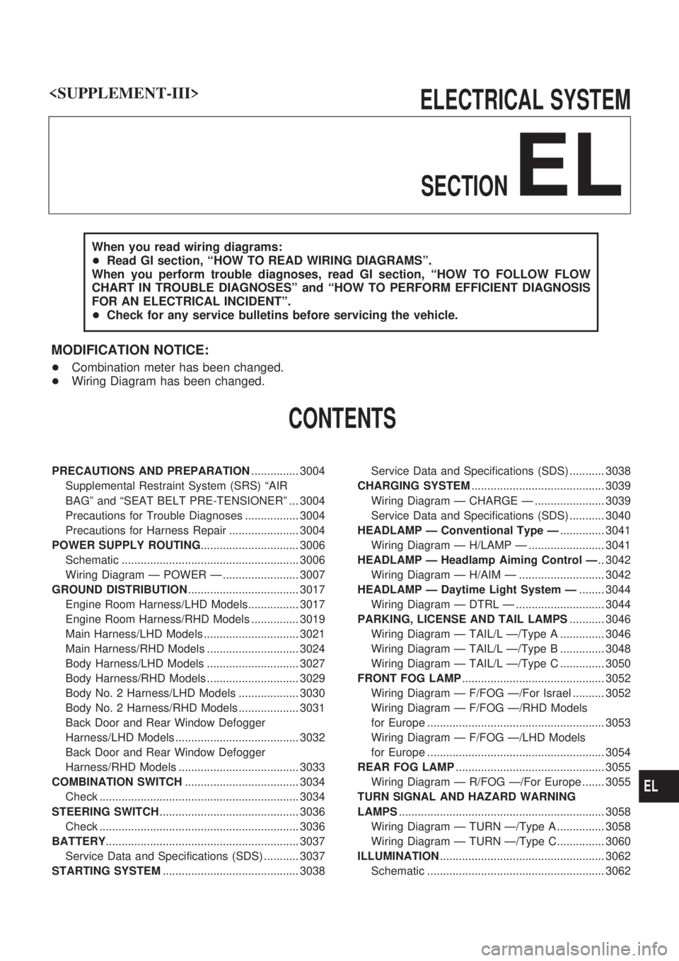
PRECAUTIONS AND PREPARATION............... 3004
Supplemental Restraint System (SRS) ªAIR
BAGº and ªSEAT BELT PRE-TENSIONERº ... 3004
Precautions for Trouble Diagnoses ................. 3004
Precautions for Harness Repair ...................... 3004
POWER SUPPLY ROUTING............................... 3006
Schematic ........................................................ 3006
Wiring Diagram Ð POWER Ð ........................ 3007
GROUND DISTRIBUTION................................... 3017
Engine Room Harness/LHD Models................ 3017
Engine Room Harness/RHD Models ............... 3019
Main Harness/LHD Models .............................. 3021
Main Harness/RHD Models ............................. 3024
Body Harness/LHD Models ............................. 3027
Body Harness/RHD Models ............................. 3029
Body No. 2 Harness/LHD Models ................... 3030
Body No. 2 Harness/RHD Models ................... 3031
Back Door and Rear Window Defogger
Harness/LHD Models ....................................... 3032
Back Door and Rear Window Defogger
Harness/RHD Models ...................................... 3033
COMBINATION SWITCH.................................... 3034
Check ............................................................... 3034
STEERING SWITCH............................................ 3036
Check ............................................................... 3036
BATTERY............................................................. 3037
Service Data and Specifications (SDS) ........... 3037
STARTING SYSTEM........................................... 3038Service Data and Specifications (SDS) ........... 3038
CHARGING SYSTEM.......................................... 3039
Wiring Diagram Ð CHARGE Ð ...................... 3039
Service Data and Specifications (SDS) ........... 3040
HEADLAMP Ð Conventional Type Ð.............. 3041
Wiring Diagram Ð H/LAMP Ð ........................ 3041
HEADLAMP Ð Headlamp Aiming Control Ð.. 3042
Wiring Diagram Ð H/AIM Ð ........................... 3042
HEADLAMP Ð Daytime Light System Ð........ 3044
Wiring Diagram Ð DTRL Ð ............................ 3044
PARKING, LICENSE AND TAIL LAMPS........... 3046
Wiring Diagram Ð TAIL/L Ð/Type A .............. 3046
Wiring Diagram Ð TAIL/L Ð/Type B .............. 3048
Wiring Diagram Ð TAIL/L Ð/Type C .............. 3050
FRONT FOG LAMP............................................. 3052
Wiring Diagram Ð F/FOG Ð/For Israel .......... 3052
Wiring Diagram Ð F/FOG Ð/RHD Models
for Europe ........................................................ 3053
Wiring Diagram Ð F/FOG Ð/LHD Models
for Europe ........................................................ 3054
REAR FOG LAMP............................................... 3055
Wiring Diagram Ð R/FOG Ð/For Europe ....... 3055
TURN SIGNAL AND HAZARD WARNING
LAMPS................................................................. 3058
Wiring Diagram Ð TURN Ð/Type A ............... 3058
Wiring Diagram Ð TURN Ð/Type C............... 3060
ILLUMINATION.................................................... 3062
Schematic ........................................................ 3062
EL
Page 85 of 311

Wiring Diagram Ð CHARGE Ð
TEL653M
CHARGING SYSTEM
EL-3039
Page 86 of 311

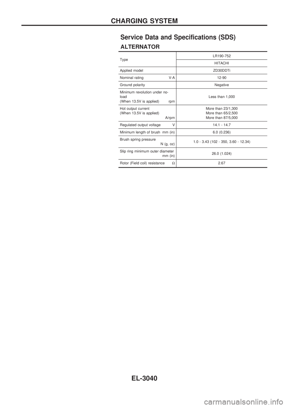
Service Data and Specifications (SDS)
ALTERNATOR
TypeLR190-752
HITACHI
Applied model ZD30DDTi
Nominal rating V-A 12-90
Ground polarity Negative
Minimum revolution under no-
load
(When 13.5V is applied) rpmLess than 1,000
Hot output current
(When 13.5V is applied)
A/rpmMore than 23/1,300
More than 65/2,500
More than 87/5,000
Regulated output voltage V 14.1 - 14.7
Minimum length of brush mm (in) 6.0 (0.236)
Brush spring pressure
N (g, oz)1.0 - 3.43 (102 - 350, 3.60 - 12.34)
Slip ring minimum outer diameter
mm (in)26.0 (1.024)
Rotor (Field coil) resistanceW2.67
CHARGING SYSTEM
EL-3040
Page 256 of 311

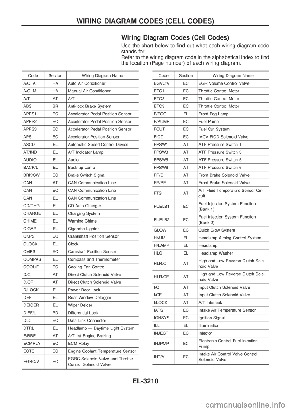
Wiring Diagram Codes (Cell Codes)
Use the chart below to find out what each wiring diagram code
stands for.
Refer to the wiring diagram code in the alphabetical index to find
the location (Page number) of each wiring diagram.
Code Section Wiring Diagram Name
A/C, A HA Auto Air Conditioner
A/C, M HA Manual Air Conditioner
A/T AT A/T
ABS BR Anti-lock Brake System
APPS1 EC Accelerator Pedal Position Sensor
APPS2 EC Accelerator Pedal Position Sensor
APPS3 EC Accelerator Pedal Position Sensor
APS EC Accelerator Position Sensor
ASCD EL Automatic Speed Control Device
AT/IND EL A/T Indicator Lamp
AUDIO EL Audio
BACK/L EL Back-up Lamp
BRK/SW EC Brake Switch Signal
CAN AT CAN Communication Line
CAN EC CAN Communication Line
CAN EL CAN Communication Line
CD/CHG EL CD Auto Changer
CHARGE EL Charging System
CHIME EL Warning Chime
CIGAR EL Cigarette Lighter
CKPS EC Crankshaft Position Sensor
CLOCK EL Clock
CMPS EC Camshaft Position Sensor
COMPAS EL Compass and Thermometer
COOL/F EC Cooling Fan Control
D/C AT Direct Clutch Solenoid Valve
D/CF AT Direct Clutch Solenoid Valve
D/LOCK EL Power Door Lock
DEF EL Rear Window Defogger
DEICER EL Wiper Deicer
DIFF/L PD Differential Lock
DLC EC Data Link Connector
DTRL EL Headlamp Ð Daytime Light System
E/BRE AT A/T 1st Engine Braking
ECMRLY EC ECM Relay
ECTS EC Engine Coolant Temperature Sensor
EGRC/V ECEGRC-Solenoid Valve and Throttle
Control Solenoid ValveCode Section Wiring Diagram Name
EGVC/V EC EGR Volume Control Valve
ETC1 EC Throttle Control Motor
ETC2 EC Throttle Control Motor
ETC3 EC Throttle Control Motor
F/FOG EL Front Fog Lamp
F/PUMP EC Fuel Pump
FCUT EC Fuel Cut System
FICD EC IACV-FICD Solenoid Valve
FPSW1 AT ATF Pressure Switch 1
FPSW3 AT ATF Pressure Switch 3
FPSW5 AT ATF Pressure Switch 5
FPSW6 AT ATF Pressure Switch 6
FR/B AT Front Brake Solenoid Valve
FR/BF AT Front Brake Solenoid Valve
FTS ATA/T Fluid Temperature Sensor Cir-
cuit
FUELB1 ECFuel Injection System Function
(Bank 1)
FUELB2 ECFuel Injection System Function
(Bank 2)
GLOW EC Quick Glow System
H/AIM EL Headlamp Aiming Control System
H/LAMP EL Headlamp
HLC EL Headlamp Washer
HLR/C ATHigh and Low Reverse Clutch Sole-
noid Valve
HLR/CF ATHigh and Low Reverse Clutch Sole-
noid Valve
I/C AT Input Clutch Solenoid Valve
I/CF AT Input Clutch Solenoid Valve
I/LOCK AT A/T Interlock
IATS EC Intake Air Temperature Sensor
IGNSYS EC Ignition Signal
ILL EL Illumination
INJECT EC Injector
INJPMP ECElectronic Control Fuel Injection
Pump
INT/V ECIntake Air Control Valve Control
Solenoid Valve
WIRING DIAGRAM CODES (CELL CODES)
EL-3210
Page 288 of 311

A
A/C control operation (auto A/C) .......... HA-3004
A/T - Wiring diagram ............................. AT-3004
ABS - Wiring diagram ........................... BR-3006
APS - Wiring diagram ........................... EC-3016
Accelerator position sensor .................. EC-3016
Alternator ............................................... EL-3040
Anti-lock brake system - Wiring
diagram ............................................. BR-3005
Audio ...................................................... EL-3109
B
Battery ................................................... EL-3037
C
CD/CHG - Wiring diagram ..................... EL-3117
CHARGE - Wiring diagram ................... EL-3039
CIGAR - Wiring diagram ....................... EL-3104
CLOCK - Wiring diagram ...................... EL-3119
COMPAS - Wiring diagram ................... EL-3083
CONSULT general information .............. GI-3002
COOL/F - Wiring diagram ..................... EC-3006
Charging system .................................... EL-3039
Cigarette lighter ..................................... EL-3104
Clock ...................................................... EL-3119
Combination meter ................................ EL-3079
Combination switch ............................... EL-3034
Cooling fan control ................................ EC-3006
D
D/LOCK - Wiring diagram ..................... EL-3121
DEICER - Wiring diagram ..................... EL-3106
DTRL - Wiring diagram ......................... EL-3044
Daytime light system ............................. EL-3044
Dimensions ............................................. GI-3007
Dome light - See Interior lamp .............. EL-3069
E
ECCS-D control module ....................... EC-3017
EGR - Wiring diagram .......................... EC-3018
EGR volume control valve .................... EC-3018
Electrical units location .......................... EL-3172
Electronic fuel injection pump ............... EC-3015
Engine control circuit diagram .............. EC-3002
F
F/FOG - Wiring diagram .............. EL-3052, 3053Fog lamp, front ...................................... EL-3052
Front disc brake .................................... BR-3002
Front fog lamp ....................................... EL-3052
Front washer .......................................... EL-3100
Front wiper ............................................. EL-3100
Fuel gauge ............................................. EL-3079
Fuse ....................................................... EL-3213
Fusible link ............................................. EL-3213
G
Gauges .................................................. EL-3079
Ground distribution ................................ EL-3017
H
H/AIM - Wiring diagram ......................... EL-3042
H/LAMP - Wiring diagram ..................... EL-3041
HLC - Wiring diagram ............................ EL-3101
Harness layout ....................................... EL-3179
Hazard warning lamp ............................ EL-3058
Headlamp aiming control ....................... EL-3042
Headlamp washer .................................. EL-3101
Headlamp .............................................. EL-3041
Height (Dimensions) ............................... GI-3007
I
ILL - Wiring diagram .............................. EL-3063
Illumination ............................................. EL-3062
Interior lamp ........................................... EL-3069
K
Keyless entry system - See Multi-remote control
system ................................................... EL-3144
L
Length (Dimensions) .............................. GI-3007
License lamp ......................................... EL-3046
Location of electrical units ..................... EL-3172
Luggage room lamp .............................. EL-3069
M
MAFS - Wiring diagram ........................ EC-3004
MAIN - Wiring diagram ......................... EC-3003
MULTI - Wiring diagram ........................ EL-3145
Meter ...................................................... EL-3079
Model variation ....................................... GI-3004
ALPHABETICAL INDEX
IDX-3002