2002 MERCEDES-BENZ S500 pre safe
[x] Cancel search: pre safePage 264 of 430
261 Driving systems
Te ch n i c a l
data Instruments
and controlsOperationDrivingInstrument
cluster displayPractical hints Car care Index Distronic (DTR)
(optional)
When activated the Distronic system increases driving
convenience, for example over long distances, as it
automatically maintains a speed set by the driver by
actively regulating the throttle setting. It also maintains
within certain limitations a preset distance to a vehicle
ahead.
With Distronic switched off, the multifunction display
continues to show the distance to the vehicle ahead, if
so selected, see page 275.
The distance warning function can be activated
separately, see page 272.
In Distronic mode, if the distance sensor detects a
slower moving vehicle directly ahead, your vehicle
speed will be reduced to the extent permitted by
reduced throttle and up to 20% of vehicle braking power,
so that you follow that vehicle at a preset distance, see
page 273.
Maximum range of detection is approximately 500 ft.
(150 m).Any given speed between 25 mph (Canada: 40 km/h)
and 110 mph (Canada: 180 km/h) can be maintained
with the Distronic by operating the control lever on the
steering column.
Wa r n i n g !
Distronic is a convenience system, its speed
adjustment reduction capability is intended to
make cruise control more effective and usable
when traffic speeds vary. It is not, however,
intended to nor does it replace the need for extreme
care. The responsibility for the vehicle speed and
the distance to the vehicle ahead, including most
importantly brake operation to assure safe stopping
distance, rests always with the driver.Distronic cannot take street and traffic conditions
into account.Wa r n i n g !
Distronic requires familiarity with its operational
characteristics. We strongly recommend that you
review the following information carefully before
operating the system.
Page 265 of 430
262 Driving systems
Te ch n i c a l
data Instruments
and controlsOperationDrivingInstrument
cluster displayPractical hints Car care Index
Note:
For operation in the USA only: This device complies
with Part 15 of the FCC Rules. Operation is subject to
the following two conditions:
(1) This device may not cause harmful interference, and
(2) this device must accept any interference received,
including interference that may cause undesired
operation.
Any unauthorized modification to this device could void
the user’s authority to operate the equipment.
Wa r n i n g !
Only use Distronic if the traffic and weather
conditions make it advisable to travel at a steady
speed.Use of Distronic can be dangerous on winding
roads or in heavy traffic because conditions do not
allow safe driving at a steady speed.
Use of Distronic can be dangerous on slippery
roads. Rapid changes in tire adhesion can result in
wheel spin and loss of control.
Distronic does not act upon adverse sight distance
conditions. Do not use Distronic during conditions
of fog and heavy rain, snow or sleet.The “Resume” function should only be operated if
the driver is fully aware of the previously set speed
and wishes to resume this particular preset speed.Distronic does not recognize accordingly and will
not react to stationary objects. It is designed and
intended only to maintain a set speed and keep a
set distance from moving objects in front of it.
Page 276 of 430

273 Driving systems
Te ch n i c a l
data Instruments
and controlsOperationDrivingInstrument
cluster displayPractical hints Car care Index Distronic settings
1Switch – for distance warning function
2Thumbwheel – for setting distance
Distronic provides a range of following distances to the
vehicle in front. The medium setting is noticeable by a
detent in the center position of the thumbwheel (2).
If you want to:
•Increase distance – turn thumbwheel (2)
towards¯.•Decrease distance – turn thumbwheel (2)
towards®.
To switch the distance warning function on or off:
To switch on – press upper half of switch (1).
The indicator lamp in the switch lights up. If the
Distronic menu is active in the multifunction display, a
loudspeaker symbol appears.
To switch off – press lower half of the switch (1).
The indicator lamp in the switch goes out. If the
Distronic menu is active in the multifunction display,
the loudspeaker symbol disappears.
See page 272 for distance warning function and
page 275 for multifunction displays.
Wa r n i n g !
It is up to the driver to exercise discretion to select
the appropriate setting given road conditions,
traffic, driver’s preferred driving style and
applicable laws and driving recommendations for
safe following distance.
Page 280 of 430
277 Driving systems
Te ch n i c a l
data Instruments
and controlsOperationDrivingInstrument
cluster displayPractical hints Car care Index Brake assist system (BAS)
The BAS is designed to maximize the vehicle’s braking
capability during emergency braking maneuvers by
having maximum power boost applied to the brakes
more quickly in emergency braking conditions than
might otherwise be afforded solely by the driver’s
braking style. This can help reduce braking distances
over what ordinary driving and braking style might do.
The BAS complements the Antilock Brake System (ABS).Applying the brakes very quickly results in maximum
BAS assistance.
To receive the benefit of the system you must apply
continuous full braking power during the stopping
sequence. Do not reduce brake pedal pressure.
Once the brake pedal is released, the BAS is deactivated.
If the BAS warning message is displayed in the
multifunction display, a malfunction has been detected
in the system. The brake system functions in the usual
manner, but without BAS.
With the ABS malfunctioning, the BAS is also switched
off.
If a BAS warning message is displayed in the
multifunction display, have the BAS checked at your
authorized Mercedes-Benz Center as soon as possible.
Wa r n i n g !
BAS cannot prevent the natural laws of physics
from acting on the vehicle, nor can it increase
braking efficiency beyond that afforded by the
condition of the vehicle brakes and tires or the
traction afforded. The BAS cannot prevent
accidents, including those resulting from excessive
speed in turns, following another vehicle too
closely, or aquaplaning. Only a safe, attentive, and
skillful driver can prevent accidents. The
capabilities of a BAS equipped car must never be
exploited in a reckless or dangerous manner which
could jeopardize the user’s safety or the safety of
others.
Page 282 of 430
279 Driving systems
Te ch n i c a l
data Instruments
and controlsOperationDrivingInstrument
cluster displayPractical hints Car care Index ABS control
The ABS malfunction indicator lamp- in the
instrument cluster comes on with the electronic key in
starter switch position 2 and should go out with the
engine running.
When the ABS malfunction indicator lamp in the
instrument cluster comes on while the engine is
running, it indicates that the ABS has detected a
malfunction and has switched off. In this case, the brake
system functions in the usual manner, but without
antilock assistance.
For ABS malfunction indicator lamp, see page 306.
With the ABS malfunctioning, the BAS and ESP are also
switched off. The ABS malfunction indicator lamp and
the ESP warning lamp come on with the engine
running.
If the charging voltage falls below 10 volts, the
malfunction indicator lamp comes on and the ABS is
switched off. When the voltage is above this value again,
the malfunction indicator lamp should go out and the
ABS is operational.If the ABS malfunction indicator lamp stays illuminated,
have the system checked at your authorized
Mercedes-Benz Center as soon as possible.
Note:
To alert following vehicles to slippery road conditions
you discover, operate your hazard warning flashers as
appropriate.
Wa r n i n g !
ABS cannot prevent the natural laws of physics
from acting on the vehicle, nor can it increase
braking or steering efficiency beyond that afforded
by the condition of the vehicle brakes and tires or
the traction afforded. The ABS cannot prevent
accidents, including those resulting from excessive
speed in turns, following another vehicle too
closely, or aquaplaning. Only a safe, attentive, and
skillful driver can prevent accidents. The
capabilities of a ABS equipped vehicle must never
be exploited in a reckless or dangerous manner
which could jeopardize the user’s safety or the
safety of others.
Page 283 of 430
280 Driving systems
Te ch n i c a l
data Instruments
and controlsOperationDrivingInstrument
cluster displayPractical hints Car care Index
Electronic stability program (ESP)
The ESP enhances directional control and reduces
driving wheel spin of the vehicle under various driving
conditions.
Over/understeering of the vehicle is counteracted by
applying brakes to the appropriate wheel to create a
countervailing vehicle movement. Engine torque is also
limited. The ESP warning lamp, located in the
speedometer dial, starts to flash when ESP is in
operation.Important!
If the ESP warning lampv flashes:
•During take-off apply as little throttle as possible.
•While driving ease up on the accelerator.
•Adapt your speed and driving to the prevailing road
conditions.
•Do not switch off the ESP.
Caution!
If the vehicle is towed with the front axle raised (see
page 361, Towing the vehicle), the engine must be shut
off (electronic key in starter switch position 0 or 1).
Otherwise, the ESP will immediately be engaged and
will apply the rear wheel brakes.
Wa r n i n g !
ESP cannot prevent the natural laws of physics
from acting on the vehicle, nor can it increase the
traction afforded. The ESP cannot prevent
accidents, including those resulting from excessive
speed in turns, or aquaplaning. Only a safe,
attentive, and skillful driver can prevent accidents.
The capabilities of an ESP equipped vehicle must
never be exploited in a reckless or dangerous
manner which could jeopardize the user’s safety or
the safety of others.
Page 288 of 430
285 Driving systems
Te ch n i c a l
data Instruments
and controlsOperationDrivingInstrument
cluster displayPractical hints Car care Index Level control system for vehicles with
Airmatic system
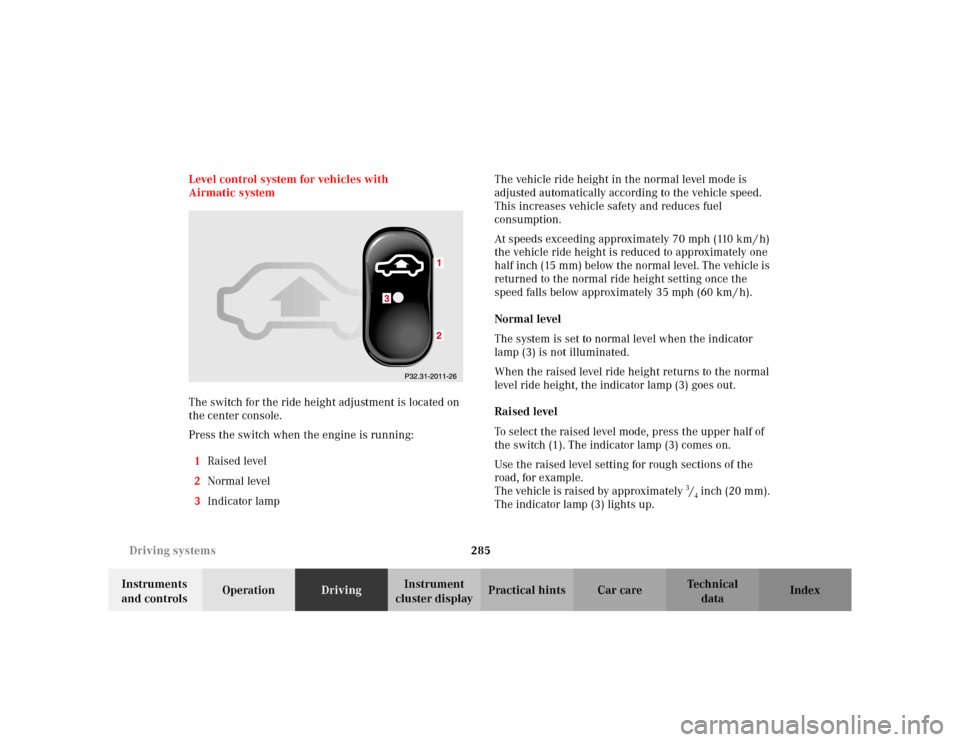
The switch for the ride height adjustment is located on
the center console.
Press the switch when the engine is running:
1Raised level
2Normal level
3Indicator lampThe vehicle ride height in the normal level mode is
adjusted automatically according to the vehicle speed.
This increases vehicle safety and reduces fuel
consumption.
At speeds exceeding approximately 70 mph (110 km / h)
the vehicle ride height is reduced to approximately one
half inch (15 mm) below the normal level. The vehicle is
returned to the normal ride height setting once the
speed falls below approximately 35 mph (60 km / h).
Normal level
The system is set to normal level when the indicator
lamp (3) is not illuminated.
When the raised level ride height returns to the normal
level ride height, the indicator lamp (3) goes out.
Raised level
To select the raised level mode, press the upper half of
the switch (1). The indicator lamp (3) comes on.
Use the raised level setting for rough sections of the
road, for example.
The vehicle is raised by approximately 3/4 inch (20 mm).
The indicator lamp (3) lights up.
Page 290 of 430
287 Driving systems
Te ch n i c a l
data Instruments
and controlsOperationDrivingInstrument
cluster displayPractical hints Car care Index The vehicle chassis ride height is raised or lowered
automatically according to the selected setting and to
the vehicle speed. This helps to increase vehicle
handling safety and lowers fuel consumption.
The selected setting is stored in memory, even with the
electronic key removed from the starter switch.
Note:
See “ACTIVE BODY CONTROL” on page 320 for
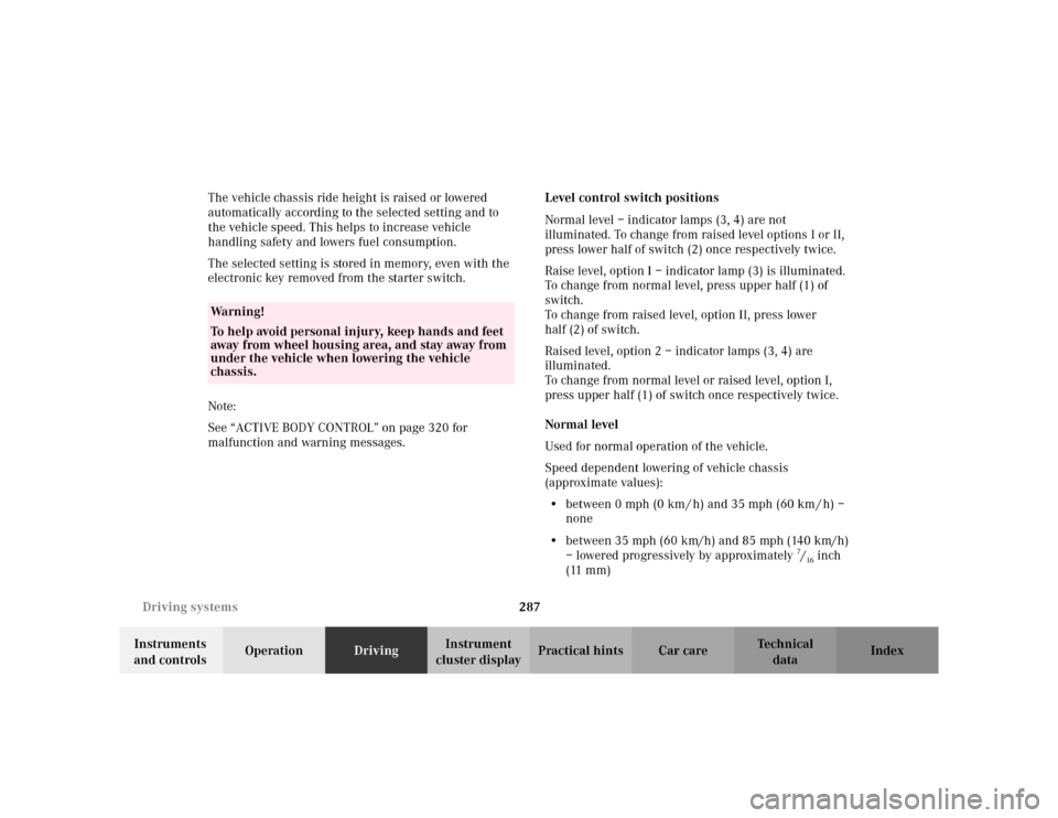
malfunction and warning messages.Level control switch positions
Normal level – indicator lamps (3, 4) are not
illuminated. To change from raised level options I or II,
press lower half of switch (2) once respectively twice.
Raise level, option I – indicator lamp (3) is illuminated.
To change from normal level, press upper half (1) of
switch.
To change from raised level, option II, press lower
half (2) of switch.
Raised level, option 2 – indicator lamps (3, 4) are
illuminated.
To change from normal level or raised level, option I,
press upper half (1) of switch once respectively twice.
Normal level
Used for normal operation of the vehicle.
Speed dependent lowering of vehicle chassis
(approximate values):
•between 0 mph (0 km / h) and 35 mph (60 km / h) –
none
•between 35 mph (60 km/h) and 85 mph (140 km/h)
– lowered progressively by approximately
7/16inch
(11 mm)
Wa r n i n g !
To help avoid personal injury, keep hands and feet
away from wheel housing area, and stay away from
under the vehicle when lowering the vehicle
chassis.