Page 69 of 342
66 Restraint systems
Te ch n i c a l
data Instruments
and controlsOperationDrivingInstrument
cluster displayPractical hints Car care Index
Safety guidelines for the seat belt,
emergency tensioning retractor and airbag
Wa r n i n g !
• Damaged seat belts or belts that were highly
stressed in an accident must be replaced and
their anchoring points must also be checked.
Use only belts installed or supplied by an
authorized Mercedes-Benz Light Truck Center.• Do not pass belts over sharp edges.• Do not make any modification that could
change the effectiveness of the belts.• Airbags and ETR’s are designed to function on
a one-time-only basis. An airbag or emergency
tensioning retractor (ETR) that was activated
must be replaced.• Do not hang items such as coat hangers from
the coat hooks or handles over the door. These
items may turn into projectiles and cause head
and other injuries when curtain airbag is
deployed.
• An airbag system component within the
steering wheel gets hot after the airbag has
inflated. Do not touch.• Improper work on the system, including
incorrect installation and removal, can lead to
possible injury through an unintended
activation of the “SRS”.• No modifications of any kind may be made to
any components or wiring of the “SRS”. This
includes changing or removing any component
or part of the “SRS”, the installation of
additional trim material, badges etc. over the
steering wheel hub, front passenger airbag
cover, or front door trim panels, and
installation of additional electrical / electronic
equipment on or near “SRS” components and
wiring. Keep area between airbags and
occupants free of objects (e.g. packages,
purses, umbrellas, etc.).
Page 77 of 342
74 Adjustable steering wheel
Te ch n i c a l
data Instruments
and controlsOperationDrivingInstrument
cluster displayPractical hints Car care Index
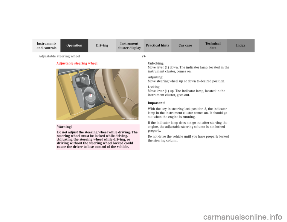
Adjustable steering wheelUnlocking:
Move lever (1) down. The indicator lamp, located in the
instrument cluster, comes on.
Adjusting:
Move steering wheel up or down to desired position.
Locking:
Move lever (1) up. The indicator lamp, located in the
instrument cluster, goes out.
Important!
With the key in steering lock position 2, the indicator
lamp in the instrument cluster comes on. It should go
out when the engine is running.
If the indicator lamp does not go out after starting the
engine, the adjustable steering column is not locked
properly.
Do not drive the vehicle until you have properly locked
the steering column.
Wa r n i n g !
Do not adjust the steering wheel while driving. The
steering wheel must be locked while driving.
Adjusting the steering wheel while driving, or
driving without the steering wheel locked could
cause the driver to lose control of the vehicle.
Page 86 of 342
83 Instrument cluster
Te ch n i c a l
data Instruments
and controlsOperationDrivingInstrument
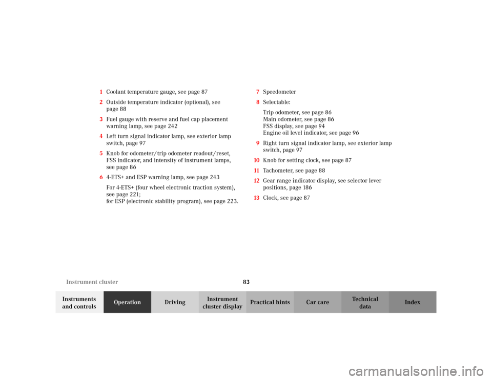
cluster displayPractical hints Car care Index 1Coolant temperature gauge, see page 87
2Outside temperature indicator (optional), see
page 88
3Fuel gauge with reserve and fuel cap placement
warning lamp, see page 242
4Left turn signal indicator lamp, see exterior lamp
switch, page 97
5Knob for odometer / trip odometer readout / reset,
FSS indicator, and intensity of instrument lamps,
see page 86
64-ETS+ and ESP warning lamp, see page 243
For 4-ETS+ (four wheel electronic traction system),
seepage221;
for ESP (electronic stability program), see page 223.7Speedometer
8Selectable:
Trip odometer, see page 86
Main odometer, see page 86
FSS display, see page 94
Engine oil level indicator, see page 96
9Right turn signal indicator lamp, see exterior lamp
switch, page 97
10Knob for setting clock, see page 87
11Tachometer, see page 88
12Gear range indicator display, see selector lever
positions, page 186
13Clock, see page 87
Page 87 of 342
84 Instrument cluster
Te ch n i c a l
data Instruments
and controlsOperationDrivingInstrument
cluster displayPractical hints Car care Index
Indicator lamps in the instrument cluster
High beam
BAS malfunction, see page 243
ESP malfunction, see page 243
4-ETS+ malfunction, see page 243
ABS malfunction, see page 244
Brake pads worn down, see page 247
Engine oil level low, see page 246
Coolant level low, see page 246
Transmission in LOW RANGE mode,
see page 243ESP and 4-ETS+. Adjust driving to road
condition, see page 243
Brake fluid low, see page 241
EBP malfunction, see page 222
Parking brake engaged, see page 191
Front passenger airbag automatically
switched off, see page 55
Front fog lamp, see page 103
Steering wheel adjustment not locked,
see page 74
Fasten seat belts,
see page 245
Battery not being charged properly,
see page 245
SRS malfunction, see page 242
Fluid level for windshield and headlamp
washer system low, see page 247.
BAS
ESPABSLOW
RANGE
BRAKESRS
Page 100 of 342
97 Exterior lamp switch
Te ch n i c a l
data Instruments
and controlsOperationDrivingInstrument
cluster displayPractical hints Car care Index Exterior lamp switch
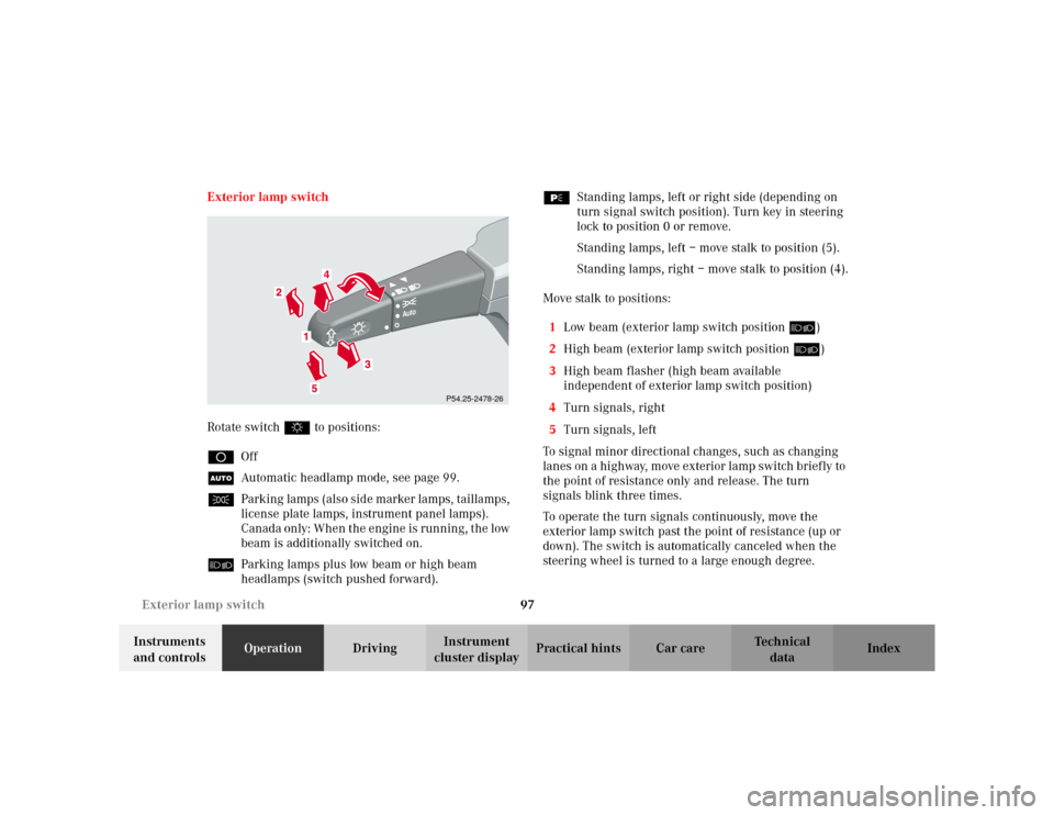
Rotate switch $ to positions:
DOff
UAutomatic headlamp mode, see page 99.
CParking lamps (also side marker lamps, taillamps,
license plate lamps, instrument panel lamps).
Canada only: When the engine is running, the low
beam is additionally switched on.
õParking lamps plus low beam or high beam
headlamps (switch pushed forward).ƒStanding lamps, left or right side (depending on
turn signal switch position). Turn key in steering
lock to position 0 or remove.
Standing lamps, left – move stalk to position (5).
Standing lamps, right – move stalk to position (4).
Move stalk to positions:
1Low beam (exterior lamp switch position õ)
2High beam (exterior lamp switch position õ)
3High beam flasher (high beam available
independent of exterior lamp switch position)
4Turn signals, right
5Turn signals, left
To signal minor directional changes, such as changing
lanes on a highway, move exterior lamp switch brief ly to
the point of resistance only and release. The turn
signals blink three times.
To operate the turn signals continuously, move the
exterior lamp switch past the point of resistance (up or
down). The switch is automatically canceled when the
steering wheel is turned to a large enough degree.
Auto
P54.25-2478-26
Page 107 of 342
104 Hazard warning flasher
Te ch n i c a l
data Instruments
and controlsOperationDrivingInstrument
cluster displayPractical hints Car care Index
Hazard warning flasher switch
The hazard warning flasher switch is located on top of
the steering column.
The hazard warning flasher can be activated either
manually via the switch located in the dashboard, or it
is activated automatically at the time an airbag is
deployed.
To activate hazard warning flasher, press switch once.
To deactivate, press switch again.
Note:
To signal turns while being towed with hazard warning
flasher in use, turn key in steering lock to position 2
and activate combination switch for left or right turn
signal in usual manner. Now deactivate the hazard
warning flasher, only the selected turn signal will
operate. Upon canceling the turn signal, the hazard
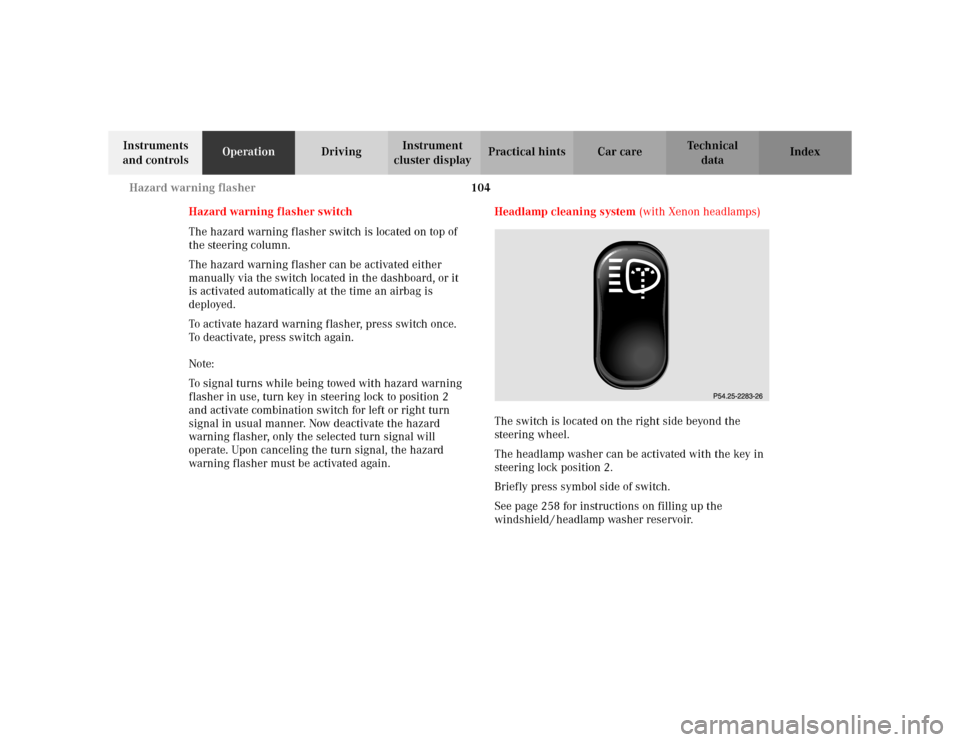
warning flasher must be activated again.Headlamp cleaning system (with Xenon headlamps)
The switch is located on the right side beyond the
steering wheel.
The headlamp washer can be activated with the key in
steering lock position 2.
Briefly press symbol side of switch.
See page 258 for instructions on filling up the
windshield / headlamp washer reservoir.
Page 108 of 342

105 Windshield wiper/washer
Te ch n i c a l
data Instruments
and controlsOperationDrivingInstrument
cluster displayPractical hints Car care Index Windshield wiper/washer switch
Move stalk briefly up for single wipe without adding
washer fluid (use only when windshield is wet).
Pull stalk toward steering wheel and hold to activate
wiper and washer.
Wiper off
Move stalk down for:
Intermittent wiping
(Interval is vehicle speed dependent
1). Optional rain sensor:
(Canada: standard on ML 500;
USA: standard on ML 55 AMG)
One initial wipe, pauses between wipes are
automatically controlled by a rain sensor
monitoring wetness of windshield.)
Notes:
With vehicle at a standstill, a front door open and
the key in steering lock position 2 there will be no
operation of windshield wipers in intermittent
setting.
With the intermittent wiping on, turn the
electronic key in steering lock from position 1 to
position 2 and keep the key in that position for
longer than 2 seconds and the wipe interval will
be set to approx. 5 seconds.
Optional rain sensor:
Do not leave in intermittent setting when vehicle
is taken to an automatic car wash or when
cleaning the windshield. Wipers will operate in
presence of water spray at windshield, and wipers
may be damaged as a result.
1 At speeds of approximately 105 mph (170 km/h) the wiper
switches automatically to continuous wiping. (Always obey local
speed limits.)
Page 112 of 342
109 Automatic climate control
Te ch n i c a l
data Instruments
and controlsOperationDrivingInstrument
cluster displayPractical hints Car care Index 1Display and controls
2Thumbwheels for the center air outlets
To open the left air and center air outlet:
Turn the left thumbwheel upward.
To open the right center air outlet:
Turn the right thumbwheel upward.
3Thumbwheels for the side air outlets
To open the side air outlets:
Turn the thumbwheels upward.
To defrost the side windows in the area around the
exterior rear view mirrors:
Turn the thumbwheel to the center position.4Center air outlets, adjustable
5Side air outlets, adjustable
6Defroster outlet windshield
Important!
The air outlets should be remain open to allow
unrestricted operation of the automatic climate control.
Notes:
For the air flow-through system to function properly, the
air vents and air outlets should be kept unobstructed.
The air outlets can be directed towards your body or
pointed upwards for draft free ventilation of the interior.