2002 MERCEDES-BENZ ML430 ESP
[x] Cancel search: ESPPage 6 of 342

3 Contents
DrivingControl and operation of
radio transmitters ..................... 164
The first 1 000 miles
(1 500 km) ................................. 165
Maintenance ................................... 165
Tele Aid ........................................... 166
Catalytic converter ........................ 178
Emission control ............................ 179
Steering lock ................................... 180
Starting and turning off
the engine .................................. 182
Automatic transmission ............... 183
Parking brake ................................. 191Driving instructions .......................192
Drive sensibly – save fuel .........192
Drinking and driving .................192
Pedals ...........................................192
Power assistance .........................193
Brakes ...........................................193
Driving off ....................................194
Parking .........................................195
Tires ..............................................195
Snow chains ................................199
Winter driving instructions ......199
Deep water .................................. 201
Passenger compartment ........... 201
Traveling abroad ........................ 201
Off-Road driving ............................ 202
Trailer towing ................................ 209
Cruise control .................................214Brake assi st system
(BAS) ........................................... 217
Antilock brake system
(ABS) ........................................... 219
Four-wheel electronic
traction system (4-ETS+) .......... 221
Electronic brake proportioning
(EBP) ...........................................222
Electronic stability program
(ESP) ...........................................223
Transmission control –
LOW RANGE mode ...................227
Parking assist
(Parktronic) ..............................230
What you should know
at the gas station .......................235
Check regularly and
before a long trip ......................238
Page 7 of 342

4 Contents
Instrument cluster displayMalfunction and
indicator lamps in
the instrument cluster .............240
On-board diagnostic system –
Check engine malfunction
indicator lamp .............................240
Brake warning lamp .................. 241
Supplemental restraint system
(SRS) indicator lamp ..................242
Fuel reserve warning .................242Electronic stability program
(ESP) / Electronic traction
system (ETS) – warning lamp .. 243
BAS/ESP malfunction
indicator lamp ............................ 243
4-ETS malfunction
indicator lamp ............................ 243
LOW RANGE
indicator lamp ............................ 243
ABS malfunction
indicator lamp ............................ 244
Adjustable steering wheel –
indicator lamp ............................ 244
AIRBAG OFF
indicator lamp ............................ 244Seat belt warning lamp .............245
Charge indicator lamp ...............245
Low engine oil level
warning lamp ..............................246
Low engine coolant level
warning ........................................246
Low windshield and
headlamp washer system fluid
level warning lamp ....................247
Brake pad wear i
ndicator lamp ..............................247
FSS indicator ...............................247
Page 10 of 342

7 IntroductionProduct information
Kindly observe the following in your own best interest:
We recommend using Mercedes-Benz original parts as well as conversion parts and accessories
explicitly approved by us for your vehicle model.
We have tested these parts to determine their reliability, safety and their special
suitability for Mercedes-Benz vehicles.
We are unable to make an assessment for other products and therefore cannot be held responsible
for them, even if in individual cases an official approval or authorization by governmental or other
agencies should exist. Use of such parts and accessories could adversely affect the safety,
performance or reliability of your vehicle. Please do not use them.
Mercedes-Benz original parts as well as conversion parts and accessories approved by us are available
at your authorized Mercedes-Benz Light Truck Center where you will receive comprehensive information, also on
permissible technical modifications, and where proper installation will be performed.
Page 13 of 342

10 Introduction
Roadside assistance
The Mercedes-Benz Roadside Assistance Program provides factory trained technical help in the event of a breakdown.
Calls to the toll-free Roadside Assistance number:
1-800-FOR-MERCedes (in the USA)
1-800-387-0100 (in Canada)
will be answered by Mercedes-Benz Customer Assistance Representatives 24 hours a day, 365 days a year.
Roadside assistance will be provided in accordance with standard program guidelines which include providing service
to the vehicle up to a reasonable distance from a paved roadway. We will make every effort to assist in a breakdown
situation, however, the accessibility of your vehicle will be determined by our authorized Mercedes-Benz Light Truck
Center technician or the tow service provider on a case by case basis and may be a factor in our ability to respond.
Additional charges may be applicable for a breakdown location determined not to be a reasonably accessible roadside
location as determined by our authorized technician and tow service provider.
For additional information refer to the Mercedes-Benz Roadside Assistance Program brochure in your glove box.
Page 22 of 342

19 Instruments and controls
Te ch n i c a l
data Instruments
and controlsOperation DrivingInstrument
cluster displayPractical hints Car care Index 1Cup holder, see page 132
2Parking brake release, see page 191
3Parking brake pedal, see page 191
4Steering wheel adjustment lever, see page 74
5Headlamp washer switch, see page 104
6Exterior lamp switch, see page 97
7Cruise control switch, see page 214
8Instrument cluster, see page 82
9Hazard warning flasher switch, see page 104
10Horn (with key in steering lock position 1 or 2),
Driver airbag, see page 58
11Steering lock with ignition / starter switch, see
page 180
12Windshield wiper / washer switch, see page 105
13Voice recognition system switch (optional only for
Canada), see separate operating instructions
14Parking assist warning indicators, see page 230
15Transmission control switch– LOW RANGE mode,
see page 22716Indicator lamp for antitheft alarm system
17Front fog lamp / rear fog lamp switch, see page 103
18MCS (Optional Modular Control System), see
separate operator’s manual
19Front passenger airbag, see page 58
20Glove box (illuminated with key in steering lock
position 1 or 2)
21Cup holder, see page 132
22Storage compartment
23Electrical outlet, see page 252
24Automatic climate control switch, see page 108
Rear window defroster switch, see page 121
25Left front seat heater switch, see page 46
26Switch for rear quarter window, left, see page 125
27Switch for rear window washer /wiper, see page 106
28ESP control switch, see page 225
29Switch for rear quarter window, right, see page 125
30Right front seat heater switch, see page 46
Page 30 of 342

27 Central locking system
Te ch n i c a l
data Instruments
and controlsOperationDrivingInstrument
cluster displayPractical hints Car care Index Locking and unlocking with remote control
Unlocking:
Press transmit button Πonce. All turn signal lamps
blink once to indicate that the driver’s door and fuel
filler flap are unlocked.
The antitheft alarm system is also deactivated.
Press transmit button Πa second time to unlock
remaining doors and liftgate.
Notes:
If the fuel filler flap cannot be opened, see page 295.
If within 40 seconds of unlocking with the remote
control, neither door nor liftgate is opened or the key is
not inserted in the steering lock, the vehicle will
automatically lock and reactivate the antitheft alarm
system.Locking:
Press transmit button ‹ once. All turn signal lamps
blink three times to indicate that the vehicle is locked
and the antitheft alarm is activated.
Notes:
If the turn signal lamps do not blink three times when
locking the vehicle, a door, the liftgate, or the hood is
not properly closed. Close the respective element and
lock the vehicle again with the remote control.
If the vehicle cannot be locked or unlocked by pressing
the transmit button, then it may be necessary to change
the batteries in the remote control or to synchronize the
remote control, see page 292 and page 293.
Unlocking the liftgate
Press transmit button Š to unlock only the liftgate.
This also deactivates the antitheft alarm.
Important!
A minimum height clearance of 7 ft. (2.15 m) is
required to open the liftgate.
Page 34 of 342

31 Central locking system
Te ch n i c a l
data Instruments
and controlsOperationDrivingInstrument
cluster displayPractical hints Car care Index Each individual door and the liftgate must be locked
with the respective door lock button – the driver’s door
can only be locked when it is closed.
Notes:
The alarm sounds when unlocking the driver’s door.
Cancel alarm by turning key in steering lock to
position 1, or with the remote control by pressing
buttonŒ or‹.
If the vehicle has previously been locked from the
outside, only the door being opened from the inside will
unlock, and the alarm will come on. The remaining
doors, the liftgate and fuel filler flap remain locked.
In case of a malfunction in the central locking system
the doors can be locked and unlocked individually.To lock, push down lock buttons and turn mechanical
key in driver’s door lock to position 3. In addition lock
the liftgate.
To unlock, pull inside door handles and turn mechanical
key in driver’s door lock to position 2.
Rear doors, previously centrally locked, can be opened
from inside by first unlocking the vehicle with the
central locking switch, see page 32, or by first pulling
up the door lock button.
If the fuel filler flap cannot be opened, see page 295.
Page 46 of 342

43 Seats
Te ch n i c a l
data Instruments
and controlsOperationDrivingInstrument
cluster displayPractical hints Car care Index Memory function
(optional; Canada only: standard on ML 500;
USA: standard on ML 55 AMG)
The memory and stored position buttons are located on
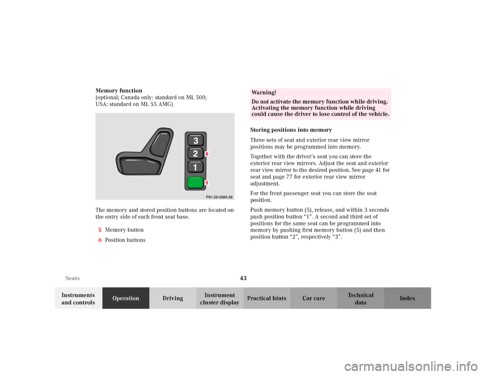
the entry side of each front seat base.
5Memory button
6Position buttonsStoring positions into memory
Three sets of seat and exterior rear view mirror
positions may be programmed into memory.
Together with the driver’s seat you can store the
exterior rear view mirrors. Adjust the seat and exterior
rear view mirror to the desired position. See page 41 for
seat and page 77 for exterior rear view mirror
adjustment.
For the front passenger seat you can store the seat
position.
Push memory button (5), release, and within 3 seconds
push position button “1”. A second and third set of
positions for the same seat can be programmed into
memory by pushing first memory button (5) and then
position button “2”, respectively “3”.
Wa r n i n g !
Do not activate the memory function while driving.
Activating the memory function while driving
could cause the driver to lose control of the vehicle.