Page 232 of 342
229 Driving systems
Te ch n i c a l
data Instruments
and controlsOperationDrivingInstrument
cluster displayPractical hints Car care Index Important!
During off-road driving a special low range system for
antilock brake system (ABS) and four-wheel electronic
traction system (4-ETS+) are operational with
transmission in the LOW RANGE mode.
In the low range mode the electronic stability program
(ESP) operates in a traction improving fashion
specifically adapted for off-road driving. At speeds
below 27 mph (45 km / h) the ESP assists in over- /
understeering, thus improving vehicle tracking.
If one or more tires lose traction while driving downhill
(accelerator released), the 4-ETS+ engages and the
warning lampv, located in the speedometer dial,
starts to flash.
When applying the service brakes at speeds below
approximately 18 mph (30 km / h), the front wheels are
locked cyclically to shorten the braking distance (dig in
effect). This affects steering the vehicle.Notes:
Driving off or driving up to 3 mph (5 km / h) with the
service brakes applied lightly (to reduce drive wheel
spin), the 4-ETS+ remains engaged. Driving with the
service brakes applied lightly at vehicles speeds above
3 mph (5 km / h), the 4-ETS+ will not engage.
If the indicator lamp blinks fast, one or more switching
conditions were not observed, or the LOW RANGE mode
is defective.
In the case of a defective in the LOW RANGE mode the
transmission shifts in the usual manner. It is not
possible to switch on the LOW RANGE mode.
Have the transmission checked at your authorized
Mercedes-Benz Light Truck Center as soon as possible.
Page 242 of 342
239 Contents - Instrument cluster display
Te ch n i c a l
data Instruments
and controlsOperation DrivingInstrument
cluster displayPractical hints Car care Index
Instrument cluster displayMalfunction and
indicator lamps in
the instrument cluster .............240
On-board diagnostic system –
Check engine malfunction
indicator lamp .............................240
Brake warning lamp .................. 241
Supplemental restraint system
(SRS) indicator lamp ..................242
Fuel reserve warning .................242Electronic stability program
(ESP) / Electronic traction
system (ETS) – warning lamp .. 243
BAS/ESP malfunction
indicator lamp ............................ 243
4-ETS malfunction
indicator lamp ............................ 243
LOW RANGE
indicator lamp ............................ 243
ABS malfunction
indicator lamp ............................ 244
Adjustable steering wheel –
indicator lamp ............................ 244
AIRBAG OFF
indicator lamp ............................ 244Seat belt warning lamp .............245
Charge indicator lamp ...............245
Low engine oil level
warning lamp ..............................246
Low engine coolant level
warning ........................................246
Low windshield and
headlamp washer system fluid
level warning lamp ....................247
Brake pad wear i
ndicator lamp ..............................247
FSS indicator ...............................247
Page 247 of 342
244 Malfunction and indicator lamps
Te ch n i c a l
data Instruments
and controlsOperation DrivingInstrument
cluster displayPractical hints Car care Index
ABS malfunction indicator lamp
The ABS malfunction indicator lamp in the
instrument cluster comes on with the key in
steering lock position 2 and should go out
with the engine running.
When the ABS malfunction indicator lamp in the
instrument cluster remains illuminated while the
engine is running, it indicates that the ABS has detected
a malfunction and has switched off. In this case, the
brake system functions in the usual manner, but
without antilock assistance.
With the ABS malfunctioning, the BAS, ESP and 4-ETS+
are also switched off. Both malfunction indicator lamps
come on with the engine running.
If the charging voltage falls below 10 volts, the
malfunction indicator lamp comes on and the ABS is
switched off. When the voltage is above this value again,
the malfunction indicator lamp should go out and the
ABS is operational.
Have the system checked at your authorized
Mercedes-Benz Light Truck Center as soon as possible.
See page 219 for notes on antilock brake system (ABS).Adjustable steering wheel – indicator lamp
The indicator lamp in the instrument cluster
comes on with the key in steering lock
position 2 and should go out with the engine
running.
If the indicator lamp does not go out after starting the
engine, the adjustable steering column is not properly
locked.
For locking the adjustable telescoping steering column,
see page 74.
AIRBAG OFF indicator lamp
The indicator lamp will light up for
approximately 6 seconds, extinguish, then
blink once, when you turn the key in
steering lock to position 1 or 2.
The 7 indicator lamp stays lit as long as a
BabySmart
TM compatible child seat is properly installed
on the front passenger seat. It indicates that the front
passenger airbag is switched off.
See page 55 for BabySmart
TM airbag and its deactivation
system.
BabySmart
TM is a trademark of Siemens Automotive Corp.
ABS
Page 271 of 342
268 Tires, Wheels
Te ch n i c a l
data Instruments
and controlsOperation DrivingInstrument
cluster displayPractical hintsCar care Index
Move vehicle to a level area which is a safe distance
from the roadway.
Important!
The vehicle doors lock if the left front wheel rotates with
the engine running. Do not leave the engine running
while changing a wheel.
1. Set parking brake and turn on hazard warning
flasher.
2. Move selector lever to position “P”, turn off the
engine, and remove key from the steering lock. Lock
steering wheel with wheels in the straight ahead
position.
3. Prevent vehicle from rolling away by blocking
wheels with wheel chocks (not supplied with
vehicle) or sizable wood block or stone. When
changing a wheel on a hill, place chocks on the
downhill side blocking both wheels of the other
axle. On a level road, place one chock in front of and
one behind the wheel that is diagonally opposite to
the wheel being changed.4. Using the wrench, loosen but do not yet remove the
wheel bolts.
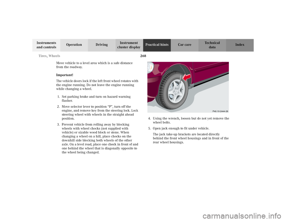
5. Open jack enough to fit under vehicle.
The jack take-up brackets are located directly
behind the front wheel housings and in front of the
rear wheel housings.
P40.10-2444-26
Page 280 of 342
277 Towing
Te ch n i c a l
data Instruments
and controlsOperation DrivingInstrument
cluster displayPractical hintsCar care Index Towing the vehicle
Important!
When towing the vehicle, please, note the following:
With the automatic central locking activated and the
engine running, the vehicle doors lock if the left front
wheel is turning at vehicle speeds of approximately
9 mph (15 km / h) or more.
To prevent the vehicle door locks from locking,
deactivate the automatic central locking, see page 33.The front towing eye is located on the passenger side
below the bumper.
1Towin g eye, fr on t
Wa r n i n g !
Prior to towing the vehicle with all wheels on the
ground, make certain that the key is in steering
lock position 2.
P88.20-2191-26
Page 282 of 342
279 Towing
Te ch n i c a l
data Instruments
and controlsOperation DrivingInstrument
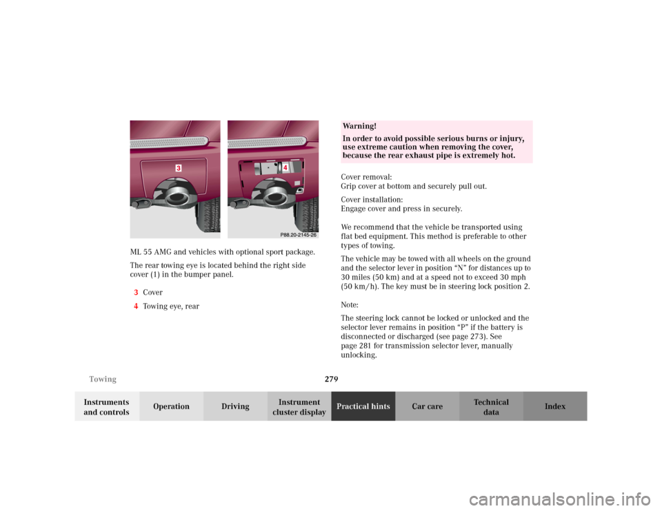
cluster displayPractical hintsCar care Index ML 55 AMG and vehicles with optional sport package.
The rear towing eye is located behind the right side
cover (1) in the bumper panel.
3Cover
4Tow i n g eye , r e a rCover removal:
Grip cover at bottom and securely pull out.
Cover installation:
Engage cover and press in securely.
We recommend that the vehicle be transported using
flat bed equipment. This method is preferable to other
types of towing.
The vehicle may be towed with all wheels on the ground
and the selector lever in position “N” for distances up to
30 miles (50 km) and at a speed not to exceed 30 mph
(50 km / h). The key must be in steering lock position 2.
Note:
The steering lock cannot be locked or unlocked and the
selector lever remains in position “P” if the battery is
disconnected or discharged (see page 273). See
page 281 for transmission selector lever, manually
unlocking.
Wa r n i n g !
In order to avoid possible serious burns or injury,
use extreme caution when removing the cover,
because the rear exhaust pipe is extremely hot.
Page 283 of 342
280 Towing
Te ch n i c a l
data Instruments
and controlsOperation DrivingInstrument
cluster displayPractical hintsCar care Index
To be certain to avoid additional damage to the vehicle
powertrain, however you should do the following:
•With damage to front axle, raise front axle. Remove
flexible drive shaft between rear axle and transfer
case
•With damage to rear axle, raise rear axle and tow
vehicle with wheel lift or dolly placed under front
wheels.
•With damage to transfer case, remove flexible drive
shafts to the drive axles.
Note:
Always install new self-locking nuts when reinstalling
the flexible drive shaft.Caution!
If the vehicle is towed with the front axle raised, the
engine must be shut off (key in steering lock position 1).
Otherwise, the 4-ETS+ may become engaged which may
cause loss of towing control. Switch off the tow-away
alarm (see page 37) as well as the ESP (see page 225).
Note:
To signal turns while being towed with hazard warning
flasher in use, turn key in steering lock to position 2
and activate combination switch for left or right turn
signal in usual manner. Now deactivate the hazard
warning flasher, only the selected turn signal will
operate. Upon canceling the turn signal, the hazard
warning flasher must be activated again.
Wa r n i n g !
With the engine not running, there is no power
assistance for the braking and steering systems. In
this case, it is important to keep in mind that a
considerably higher degree of effort is necessary to
brake and steer the vehicle.
Page 300 of 342
297 Contents - Car care
Te ch n i c a l
data Instruments
and controlsOperation DrivingInstrument
cluster displayPractical hintsCar careIndex
Vehicle careCleaning and care of the vehicle .298
Power washer ..............................299
Tar stains .....................................299
Paintwork, painted body
components .................................299
Engine cleaning ..........................300
Vehicle washing .........................300
Ornamental moldings ................300
Headlamps, taillamps,
turn signal lenses ......................300
Cleaning the parktronic
system sensors ........................... 301Window cleaning ....................... 301
Wiper blades .............................. 301
Light alloy wheels ..................... 302
Instrument cluster ..................... 302
Steering wheel and
gear selector lever ..................... 302
Cup holder .................................. 302
Seat belts ..................................... 302
Headliner .................................... 302
Upholstery .................................. 303
Hard plastic trim items ............. 303
Plastic and rubber parts ........... 303