Page 178 of 385
175 Interior equipment
Te ch n i c a l
data Instruments
and controlsOperationDrivingInstrument
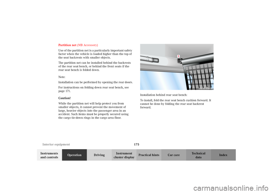
cluster displayPractical hints Car care Index Partition net (MB Accessory)
Us e of t he p artition n et is a p artic ular ly important s afety
factor when the vehicle is loaded higher than the top of
the seat backrests with smaller objects.
The partition net can be installed behind the backrests
of the rear seat bench, or behind the front seats if the
rear seat bench is folded down.
Note:
Installation can be performed by opening the rear doors.
For instructions on folding down rear seat bench, see
page 171.
Caution!
While the partition net will help protect you from
smaller objects, it cannot prevent the movement of
large, heavier objects into the passenger area in an
accident. Such items must be properly secured using
the cargo tie-down rings in the cargo area floor.Installation behind rear seat bench:
To install, fold the rear seat bench cushion forward. It
cannot be done by folding the rear seat backrest
forward.
J_G463.book Seite 175 Mittwoch, 19. September 2001 8:06 08
Page 181 of 385
178 Interior equipment
Te ch n i c a l
data Instruments
and controlsOperationDrivingInstrument
cluster displayPractical hints Car care Index
Removal:
1. Lift tensioner upward to a horizontal position to
release tensioning of strap.
2. Disengage tie down hooks from rings.
3. Remove partition net from holders.
Storage:
1. Roll up partition net and secure it.
2. Store partition net behind rear seat bench.Loading instructions
The total load weight including vehicle occupants and
luggage / cargo should not exceed the vehicle capacity
weight indicated on the certification label which can be
found on the left door pillar.
The handling characteristics of a fully loaded vehicle
depend greatly on the load distribution. It is therefore
recommended to load the vehicle according to the
illustrations shown, with the heaviest items being
placed towards the front of the vehicle.
P97.00-2004-26
J_G463.book Seite 178 Mittwoch, 19. September 2001 8:06 08
Page 182 of 385
179 Interior equipment
Te ch n i c a l
data Instruments
and controlsOperationDrivingInstrument
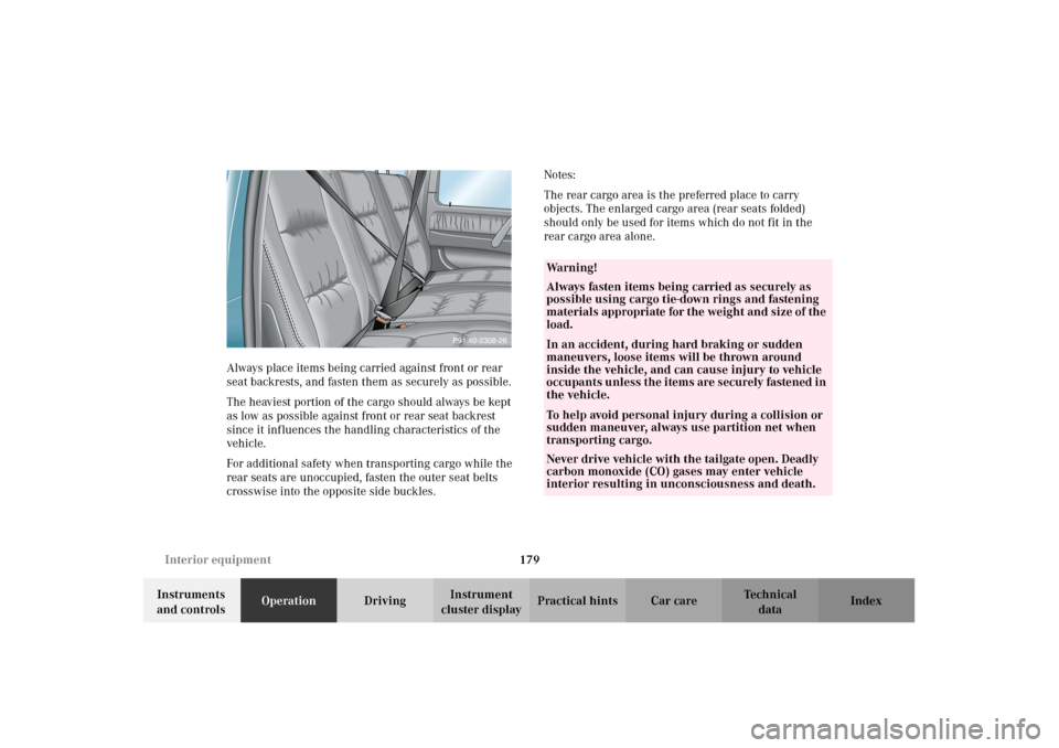
cluster displayPractical hints Car care Index Always place items being carried against front or rear
seat backrests, and fasten them as securely as possible.
The heaviest portion of the cargo should always be kept
as low as possible against front or rear seat backrest
since it influences the handling characteristics of the
vehicle.
For additional safety when transporting cargo while the
rear seats are unoccupied, fasten the outer seat belts
crosswise into the opposite side buckles.Notes:
The rear cargo area is the preferred place to carry
objects. The enlarged cargo area (rear seats folded)
should only be used for items which do not fit in the
rear cargo area alone.
Wa r n i n g !
Always fasten items being carried as securely as
possible using cargo tie-down rings and fastening
materials appropriate for the weight and size of the
load.In an accident, during hard braking or sudden
maneuvers, loose items will be thrown around
inside the vehicle, and can cause injury to vehicle
oc cu pa nt s u nl ess t he i tem s are s ecurely fastened i n
the vehicle.To help avoid personal injury during a collision or
sudden maneuver, always use partition net when
transporting cargo.
Never drive vehicle with the tailgate open. Deadly
carbon monoxide (CO) gases may enter vehicle
interior resulting in unconsciousness and death.
J_G463.book Seite 179 Mittwoch, 19. September 2001 8:06 08
Page 186 of 385
183 Interior equipment
Te ch n i c a l
data Instruments
and controlsOperationDrivingInstrument
cluster displayPractical hints Car care Index 1Lock and unlocking handle
2Quick Lock
3Lock
4End stop joint
To lower brush guard:
While holding brush guard firmly, open quick lock (2)
using lock an d un lock in g hand le (1 ). Gen tly lower b rush
guard until it reaches its fully lowered position.To raise and secure brush guard:
Flip up brush guard until it contacts end stop joint (4).
The quick lock stop pin (2) must engage the cross slot
recess in the lock (3).
Now turn quick lock (2) so that quick lock is making
contact with end stop joint (4).
Lock quick lock (2) on both sides of brush guard using
lock and unlocking handle (1).
Important!
Make sure that both quick lock stop pins (2) are seated
fully in lock (3).
J_G463.book Seite 183 Mittwoch, 19. September 2001 8:06 08
Page 213 of 385
210 Automatic transmission
Te ch n i c a l
data Instruments
and controlsOperationDrivingInstrument
cluster displayPractical hints Car care Index
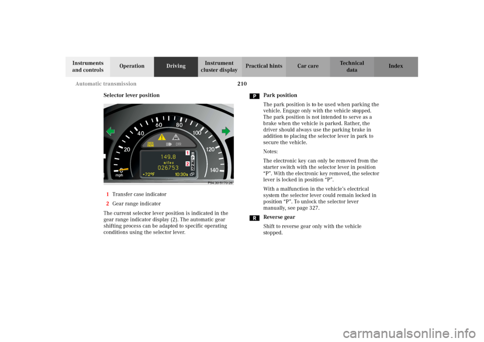
Selector lever position
1Transfer case indicator
2Gear range indicator
The current selector lever position is indicated in the
gear range indicator display (2). The automatic gear
shifting process can be adapted to specific operating
conditions using the selector lever.Park position
The park position is to be used when parking the
vehicle. Engage only with the vehicle stopped.
The park position is not intended to serve as a
brake when the vehicle is parked. Rather, the
driver should always use the parking brake in
addition to placing the selector lever in park to
secure the vehicle.
Notes:
The electronic key can only be removed from the
starter switch with the selector lever in position
“P”. With the electronic key removed, the selector
lever is locked in position “P”.
With a malfunction in the vehicle’s electrical
system the selector lever could remain locked in
position “P”. To unlock the selector lever
manually, see page 327.
Reverse gear
Shift to reverse gear only with the vehicle
stopped.
0
60
40100
120
140
mph
2080
P54.30-5170-26
J_G463.book Seite 210 Mittwoch, 19. September 2001 8:06 08
Page 228 of 385
225 Driving instructions
Te ch n i c a l
data Instruments
and controlsOperationDrivingInstrument
cluster displayPractical hints Car care Index Passenger compartment
Block heater (Canada only)
The engine is equipped with a block heater.
The electrical cable may be installed at your authorized
Mercedes-Benz Light Truck Center.Traveling abroad
Abroad, there is a widely-spread Mercedes-Benz service
network at your disposal. If you plan to travel into areas
which are not listed in the index of your Mercedes-Benz
Light Truck Center directory, you should request
pertinent information from your authorized
Mercedes-Benz Light Truck Center.
Wa r n i n g !
Always fasten items being carried as securely as
possible.In an accident, during hard braking or sudden
maneuvers, loose items will be thrown around
inside the vehicle, and cause injury to vehicle
occupants unless the items are securely fastened in
the vehicle.The rear cargo area is the preferred place to carry
objects.Do not load items on the roof. It may cause
instability during some maneuvers which could
result in an accident. This vehicle is not intended
to carry items on its roof. Thus roof rails and roof
mounted ski or bike holders must not be used.
J_G463.book Seite 225 Mittwoch, 19. September 2001 8:06 08
Page 229 of 385
226 Driving instructions
Te ch n i c a l
data Instruments
and controlsOperationDrivingInstrument
cluster displayPractical hints Car care Index
Off-Road driving
Familiarize yourself with the vehicle characteristics and
gear changing before you attempt any difficult terrain
off-road driving. We recommend that you start out with
easy off-road travel.
Please read this chapter carefully before you begin
off-road travel.
Special driving features are available for specific kinds
of operation:
•ABS, see page 239
•ESP, see page 243
•Differential lock, see page 253
•Transfer case, see page 247
Engage the transfer case in position LOW before driving
under off-road conditions. For switching the transfer
case in position LOW, see page 247.Fasten items being carried as securely as possible, see
page 178.
We recommend to keep doors, tailgate, windows, and
roof closed whenever driving in off-road mode.
We recommend to switch the cruise control off.
Important!
Adjust vehicle speed to condition of terrain. The more
uneven, rutty and steeper the terrain, the lower the
speed should be.
Watch out for obstacles, such as rocks, holes,
tree-stumps, ruts.
Wa r n i n g !
Do not load items on the roof. It may cause
instability during some maneuvers which could
result in an accident.
J_G463.book Seite 226 Mittwoch, 19. September 2001 8:06 08
Page 268 of 385
265 Malfunction and indicator lamps
Te ch n i c a l
data Instruments
and controlsOperation DrivingInstrument
cluster displayPractical hints Car care Index On-board diagnostic system
Check engine malfunction indicator lamp
Engine malfunction indicator lamp. If the
“CHECK ENGINE” malfunction indicator
lamp comes on when the engine is running,
it indicates a malfunction of the fuel management
system, emission control system, systems which impact
emissions, or the fuel cap is not closed tight (check the
fuel cap). If the “CHECK ENGINE” lamp is illuminated
continuously and the vehicle is driving normally, you
may still drive the vehicle, however, in all cases, we
recommend that you have the system checked at your
authorized Mercedes-Benz Light Truck Center as soon
as possible.
If the “CHECK ENGINE” lamp comes on continuously
and / or the vehicle is not driving normally (e.g.
malfunction of the fuel management system or running
out of fuel), serious damage can occur to the emission
system. Please contact your authorized Mercedes-Benz
Light Truck Center immediately.The Sequential Multiport Fuel Injection (SFI) control
module monitors emission control components that
either provide input signals to or receive output signals
from the control module. Malfunctions resulting from
interruptions or failure of any of these components are
indicated by the “CHECK ENGINE” malfunction
indicator lamp in the instrument cluster and are
simultaneously stored in the SFI control module.
If the “CHECK ENGINE” malfunction indicator lamp
comes on, have the system checked at your authorized
Mercedes-Benz Light Truck Center as soon as possible.
With some exceptions, the control module switches off
the “CHECK ENGINE” malfunction indicator lamp if the
condition, causing the lamp to come on, no longer exists
during three consecutive cycles.
An on-board diagnostic connector is located in
passenger compartment on the driver’s side near hood
lock release on the upper left of footwell, allowing the
accurate identification of system malfunctions through
the readout of diagnostic trouble codes.
J_G463.book Seite 265 Mittwoch, 19. September 2001 8:06 08