2002 MERCEDES-BENZ G500 Light
[x] Cancel search: LightPage 251 of 385
248 Driving systems
Te ch n i c a l
data Instruments
and controlsOperationDrivingInstrument
cluster displayPractical hints Car care Index
Switching transfer case
Switching from “HIGH” to “LOW”:
•The shift procedure can only be performed with the
engine running.
•The vehicle speed must not exceed 25 mph
(40 km / h).
•Move selector lever for the automatic transmission
to position “N”, see page 207.
Press the “LOW” switch (1).
Once the shift is complete, the gear position “L” is
displayed in the transfer case indicator (3).
If the multifunction display shows the message
“TC SHIFT CONDITIONS NOT FULFILLED”, the shift
does not occur.
At least one shif t con dition was n ot me t. Repe at t he shif t
procedure.
Note:
Do not depress the accelerator when switching the
automatic transmission from position “N” to “D”.If the multifunction display shows the message
“TC IN NEUTRAL”, the shift does not occur.
The transfer case is in neutral. The gear position “N” is
displayed in the transfer case indicator (3). Repeat the
shift procedure.
If the multifunction display shows the message
“TC SHIFT – CANCELLED”, the shift did not take place.
Repeat the shift procedure.
If the multifunction display shows the message
“TRANSFER CASE – VISIT WORKSHOP!”, there is a
malfunction in the system.
Have the vehicle checked at your authorized Mercedes-
Benz Light Truck Center as soon as possible.
For malfunction and warning messages in the
multifunction display, see page 272.
Wa r n i n g !
If TC is in neutral, the “P” position of transmission
will not hold vehicle. The parking brake must be
applied to hold vehicle in place.
J_G463.book Seite 248 Mittwoch, 19. September 2001 8:06 08
Page 253 of 385
250 Driving systems
Te ch n i c a l
data Instruments
and controlsOperationDrivingInstrument
cluster displayPractical hints Car care Index
If the multifunction display shows the message
“TC IN NEUTRAL”, the shift does not occur.
The transfer case is in neutral. The gear position “N” is
displayed in the transfer case indicator (3). Repeat the
shift procedure.
If the multifunction display shows the message
“TC SHIFT – CANCELLED”, the shift did not take place.
Repeat the shift procedure.
If the multifunction display shows the message
“TRANSFER CASE – VISIT WORKSHOP!”, there is a
malfunction in the system.
Have the vehicle checked at your authorized Mercedes-
Benz Light Truck Center as soon as possible.
For malfunction and warning messages in the
multifunction display, see page 272.Note:
If the electronic key is in starter switch position 0 or 1,
an alarm will sound if the transfer case is in
position “N” and the drivers door is opened.
Engage transfer case to gear position “HIGH” or “LOW”.
Wa r n i n g !
If TC is in neutral, the “P” position of transmission
will not hold vehicle. The parking brake must be
applied to hold vehicle in place.
J_G463.book Seite 250 Mittwoch, 19. September 2001 8:06 08
Page 254 of 385
251 Driving systems
Te ch n i c a l
data Instruments
and controlsOperationDrivingInstrument
cluster displayPractical hints Car care Index A few words about differentials and differential
locks
When a vehicle negotiates a turn, wheels on the outside
of the curve must travel farther and rotate faster than
the inside wheels. The differential, the operation of a set
of gears that allow the powered wheels in a vehicle to
turn a different speeds, provides for this essential
function.
The drawback is that the differential also sends most of
the engine's power to the wheel with the least load or
strain on it. For example, if one of a vehicle's powered
wheels sits on a patch of snow and spins because there
is no traction, all of the engine's power will go to that
wheel because the power will take the path of least
resistance. Meanwhile, the opposite wheel, sitting on
dry pavement where it could get enough grip to start the
vehicle moving, sits idle because it gets no power.
The Electronic Traction System (ETS) addresses this
problem and provides for good control and steering
ability by automatically slowing the slipping wheel and
thus increasing the power to the other non-slipping
d rive whee ls to get t he ve hicle m ovin g. The ESP and ETS
in this vehicle feature such intelligent limited-slip
differential technology, ideally suited for on-road and light off-road driving. The position “LOW” of the
transfer case (see pages 247and 226) also enhances
off-road driving capabilities.
More extreme off-road conditions may call for another
cure which is to engage a differential lock, preventing
the differential from operating altogether. This vehicle
offers as standard equipment three differential locks:
front, transfer case (center), and rear. Each can be
engaged simply by pushing a dashboard-mounted
button (see pages 253 and 254 for engaging differential
locks). When the transfer case (center) differential is
locked, half of the engine's power is automatically
distributed to the front wheels and half to the rear
wheels. When the rear differential is locked, power
going to the rear wheels is equally distributed, so that
both rear wheels turn at the same speed and torque.
When the front differential is locked, all four wheels
now turn with equal power and torque. Please be aware
that engaging the differential locks will significantly
reduce steering ability of the vehicle.
J_G463.book Seite 251 Mittwoch, 19. September 2001 8:06 08
Page 258 of 385
255 Driving systems
Te ch n i c a l
data Instruments
and controlsOperationDrivingInstrument
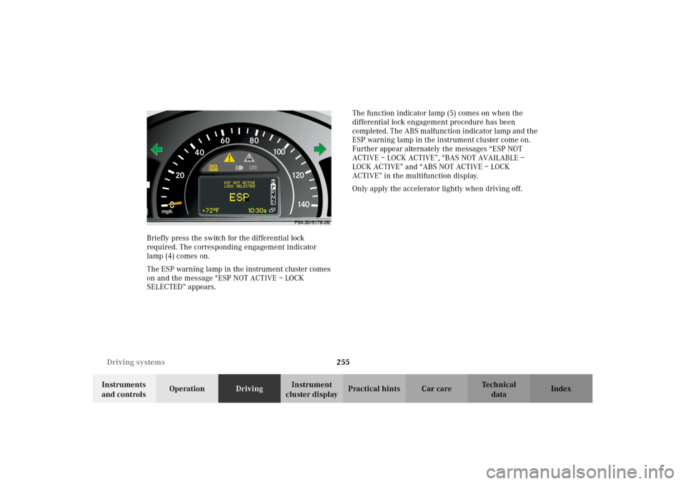
cluster displayPractical hints Car care Index Briefly press the switch for the differential lock
required. The corresponding engagement indicator
lamp (4) comes on.
The ESP warning lamp in the instrument cluster comes
on and the message “ESP NOT ACTIVE – LOCK
SELECTED” appears.The function indicator lamp (5) comes on when the
differential lock engagement procedure has been
completed. The ABS malfunction indicator lamp and the
ESP warning lamp in the instrument cluster come on.
Further appear alternately the messages “ESP NOT
ACTIVE – LOCK ACTIVE”, “BAS NOT AVAILABLE –
LOCK ACTIVE” and “ABS NOT ACTIVE – LOCK
ACTIVE” in the multifunction display.
Only apply the accelerator lightly when driving off.
J_G463.book Seite 255 Mittwoch, 19. September 2001 8:06 08
Page 264 of 385
261 Check regulary and before a long trip
Te ch n i c a l
data Instruments
and controlsOperationDrivingInstrument
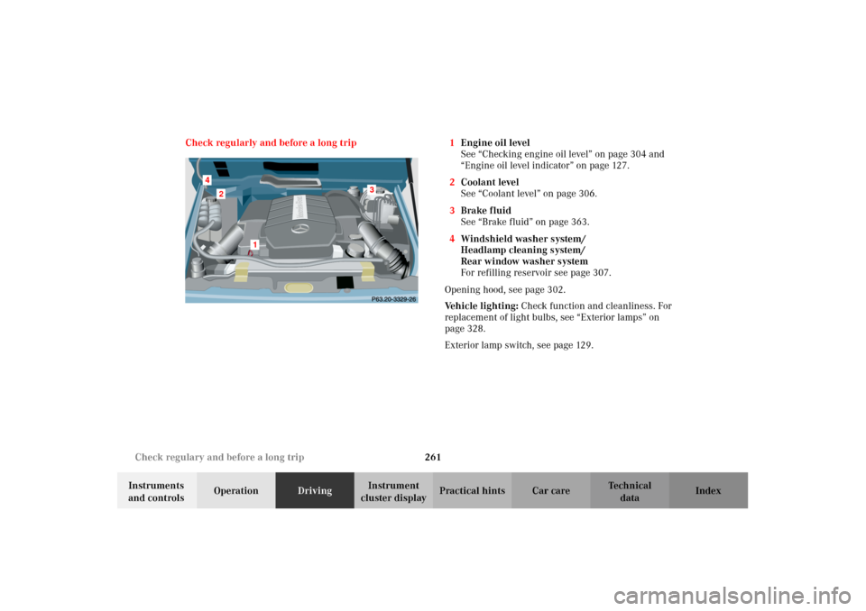
cluster displayPractical hints Car care Index Check regularly and before a long trip 1Engine oil level
See “Checking engine oil level” on page 304 and
“Engine oil level indicator” on page 127.
2Coolant level
See “Coolant level” on page 306.
3Brake fluid
See “Brake fluid” on page 363.
4Windshield washer system/
Headlamp cleaning system/
Rear window washer system
For refilling reservoir see page 307.
Opening hood, see page 302.
Vehicle lighting: Check function and cleanliness. For
replacement of light bulbs, see “Exterior lamps” on
page 328.
Exterior lamp switch, see page 129.
2
1
3
4
J_G463.book Seite 261 Mittwoch, 19. September 2001 8:06 08
Page 266 of 385
263 Contents - Instrument cluster display
Te ch n i c a l
data Instruments
and controlsOperation DrivingInstrument
cluster displayPractical hints Car care Index
Instrument cluster displayMalfunction and indicator
lamps in the
instrument cluster ....................264
On-board diagnostic system .........265
Check engine malfunction
indicator lamp .............................265
Brake warning lamp ..................266
Supplemental restraint system
(SRS) indicator lamp ..................267
Fuel reserve warning .................268
ABS malfunction
indicator lamp .............................269
Electronic stability program
(ESP) — warning lamp ...............270
Seat belt nonusage
warning lamp .............................270
Malfunction and indicator lamp
in the center console ................ 271
AIRBAG OFF indicator lamp ..... 271Malfunction and warning
messages in the
multifunction display .............. 272
DISPLAY DEFECTIVE
(engine control unit) ................. 273
DISPLAY DEFECTIVE
(several systems) ....................... 273
BATTERY / ALTERNATOR ........274
ANTILOCK BRAKE SYSTEM .... 275
BRAKE ASSIST ............................276
BRAKE PAD WEAR .................... 277
BRAKE FLUID ............................ 277
PARKING BRAKE ....................... 278
SEAT BELT SYSTEM .................. 278
ELEC. STABIL. PROG.
(Electronic stability program) . 279
COOLANT
(coolant level) ............................. 280
COOLANT
(coolant temperature) ............... 281
ENGINE OIL LEVEL ................... 282LIGHTING SYSTEM ....................283
LIGHT SENSOR ...........................285
DOOR ...........................................285
TRUNK OPEN .............................286
HOOD ...........................................286
TELEPHONE – FUNCTION .......287
TELE AID .....................................287
WASHER FLUID .........................288
RESTRAINT SYSTEM .................289
KEY ...............................................289
FUEL RESERVE ..........................290
UNDERVOLTAGE ........................290
ELECTRONIC BRAKE BOOSTER
(EBB) ............................................ 291
ENGINE AIR FILTER .................. 291
TC SHIFT ....................................292
TC SHIFT CONDITIONS ............292
TC IN NEUTRAL .........................293
TRANSFER CASE .......................293
J_G463.book Seite 263 Mittwoch, 19. September 2001 8:06 08
Page 267 of 385
264 Malfunction and indicator lamps
Te ch n i c a l
data Instruments
and controlsOperation DrivingInstrument
cluster displayPractical hints Car care Index
Malfunction and indicator lamps
in the instrument cluster
General information:
If a bulb in the instrument cluster fails to light up
during the bulb self-check when turning the key in
starter switch to position 2, have it checked and
replaced if necessary.
Emission control
Certain systems of the engine serve to keep the toxic
components of the exhaust gases within permissible
limits required by law.
These systems, of course, will function properly only
when maintained strictly according to factory
specifications. Any adjustments on the engine should,
therefore, be carried out only by authorized
Mercedes-Benz Light Truck Center qualified
technicians. Engine adjustments should not be altered
in any way. Moreover, the specified service jobs must be
carried out regularly according to Mercedes-Benz
servicing requirements. For details refer to the Service
Booklet.
Wa r n i n g !
Inhalation of exhaust gas is hazardous to your
health. All exhaust gas contains carbon monoxide,
and inhaling it can cause unconsciousness and
lead to death. Do not run the engine in confined areas (such as a
garage) which are not properly ventilated. If you
think that exhaust gas fumes are entering the
vehicle while driving, have the cause determined
and corrected immediately. If you must drive under
these conditions, drive only with at least one
window fully open.
J_G463.book Seite 264 Mittwoch, 19. September 2001 8:06 08
Page 268 of 385
265 Malfunction and indicator lamps
Te ch n i c a l
data Instruments
and controlsOperation DrivingInstrument
cluster displayPractical hints Car care Index On-board diagnostic system
Check engine malfunction indicator lamp
Engine malfunction indicator lamp. If the
“CHECK ENGINE” malfunction indicator
lamp comes on when the engine is running,
it indicates a malfunction of the fuel management
system, emission control system, systems which impact
emissions, or the fuel cap is not closed tight (check the
fuel cap). If the “CHECK ENGINE” lamp is illuminated
continuously and the vehicle is driving normally, you
may still drive the vehicle, however, in all cases, we
recommend that you have the system checked at your
authorized Mercedes-Benz Light Truck Center as soon
as possible.
If the “CHECK ENGINE” lamp comes on continuously
and / or the vehicle is not driving normally (e.g.
malfunction of the fuel management system or running
out of fuel), serious damage can occur to the emission
system. Please contact your authorized Mercedes-Benz
Light Truck Center immediately.The Sequential Multiport Fuel Injection (SFI) control
module monitors emission control components that
either provide input signals to or receive output signals
from the control module. Malfunctions resulting from
interruptions or failure of any of these components are
indicated by the “CHECK ENGINE” malfunction
indicator lamp in the instrument cluster and are
simultaneously stored in the SFI control module.
If the “CHECK ENGINE” malfunction indicator lamp
comes on, have the system checked at your authorized
Mercedes-Benz Light Truck Center as soon as possible.
With some exceptions, the control module switches off
the “CHECK ENGINE” malfunction indicator lamp if the
condition, causing the lamp to come on, no longer exists
during three consecutive cycles.
An on-board diagnostic connector is located in
passenger compartment on the driver’s side near hood
lock release on the upper left of footwell, allowing the
accurate identification of system malfunctions through
the readout of diagnostic trouble codes.
J_G463.book Seite 265 Mittwoch, 19. September 2001 8:06 08