2002 MERCEDES-BENZ G500 Light
[x] Cancel search: LightPage 179 of 385
176 Interior equipment
Te ch n i c a l
data Instruments
and controlsOperationDrivingInstrument
cluster displayPractical hints Car care Index
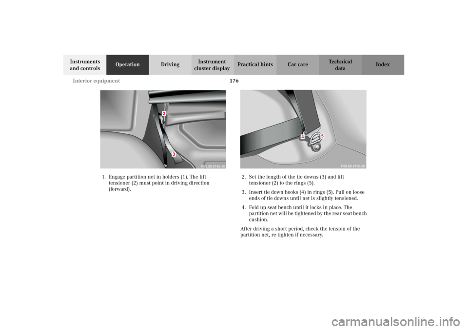
1. Engage partition net in holders (1). The lift
tensioner (2) must point in driving direction
(forward).2. Set the length of the tie downs (3) and lift
tensioner (2) to the rings (5).
3. Insert tie down hooks (4) in rings (5). Pull on loose
ends of tie downs until net is slightly tensioned.
4. Fold up seat bench until it locks in place. The
p artition n et will be tightene d by t he r ear s eat b en ch
cushion.
After driving a short period, check the tension of the
partition net, re-tighten if necessary.
4
5
J_G463.book Seite 176 Mittwoch, 19. September 2001 8:06 08
Page 183 of 385
180 Interior equipment
Te ch n i c a l
data Instruments
and controlsOperationDrivingInstrument
cluster displayPractical hints Car care Index
Parcel net in front passenger footwell
A small convenience parcel net is located in the front
passenger footwell. It is for small and light items, such
as road maps, mail, etc..
Note:
With large objects stored in the parcel net do not slide
the seat fully forward, it could damage them.Cargo area cover blind
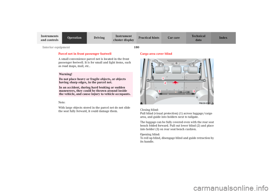
Closing blind:
Pull blind (visual protection) (1) across luggage / cargo
area, and guide into holders next to tailgate.
The luggage can be fully covered even with the rear seat
bench folded forward. Pull out lower blind (2) and place
into holder (3) on rear seat bench cushion.
Opening blind:
To roll up blind, disengage blind and guide retraction by
its handle.
Wa r n i n g !
Do not place heavy or fragile objects, or objects
having sharp edges, in the parcel net.In an accident, during hard braking or sudden
maneuvers, they could be thrown around inside
the vehicle, and cause injury to vehicle occupants.
21
3
3
J_G463.book Seite 180 Mittwoch, 19. September 2001 8:06 08
Page 185 of 385
182 Interior equipment
Te ch n i c a l
data Instruments
and controlsOperationDrivingInstrument
cluster displayPractical hints Car care Index
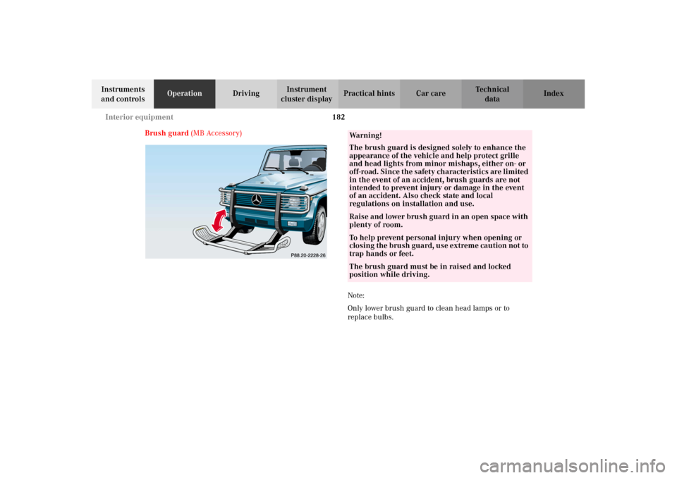
Brush guard (MB Accessory)
Note:
Only lower brush guard to clean head lamps or to
replace bulbs.
Wa r n i n g !
The brush guard is designed solely to enhance the
appearance of the vehicle and help protect grille
and head lights from minor mishaps, either on- or
off-road. Since the safety characteristics are limited
in the event of an accident, brush guards are not
intended to prevent injury or damage in the event
of an accident. Also check state and local
regulations on installation and use.Raise and lower brush guard in an open space with
plenty of room.To help prevent personal injury when opening or
c los in g the b rush gua rd, us e extrem e ca uti on n ot to
trap hands or feet.The brush guard must be in raised and locked
position while driving.
J_G463.book Seite 182 Mittwoch, 19. September 2001 8:06 08
Page 188 of 385
185 Garage door opener
Te ch n i c a l
data Instruments
and controlsOperationDrivingInstrument
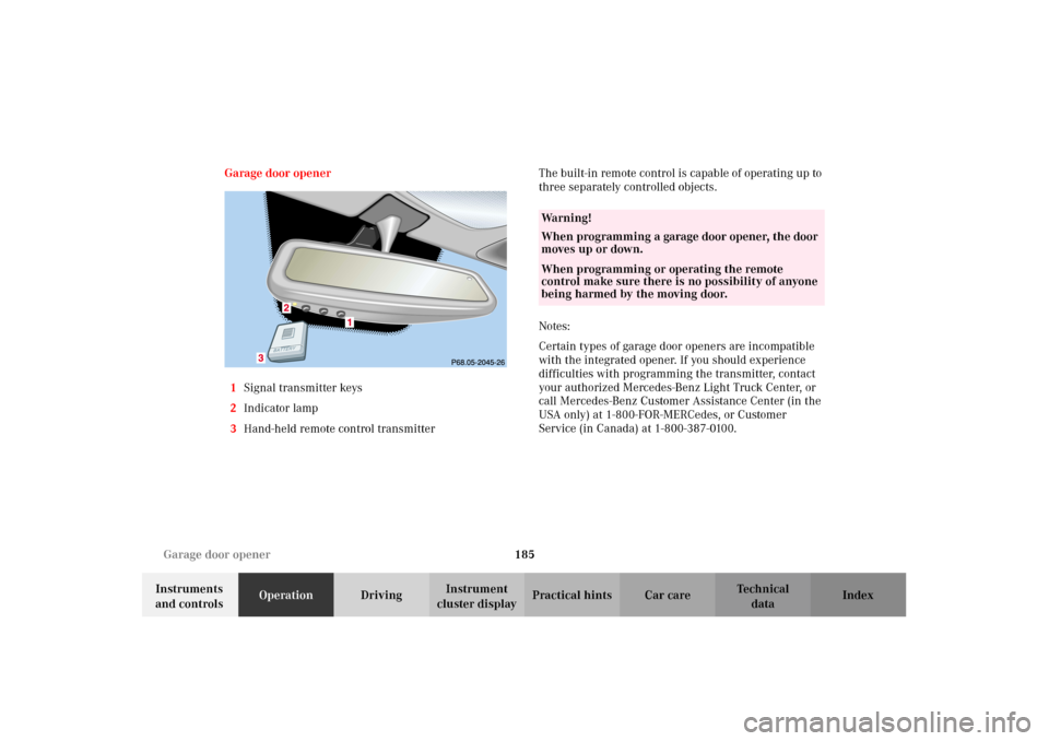
cluster displayPractical hints Car care Index Garage door opener
1Signal transmitter keys
2Indicator lamp
3Hand-held remote control transmitterThe built-in remote control is capable of operating up to
three separately controlled objects.
Notes:
Certain types of garage door openers are incompatible
with the integrated opener. If you should experience
difficulties with programming the transmitter, contact
your authorized Mercedes-Benz Light Truck Center, or
call Mercedes-Benz Customer Assistance Center (in the
USA only) at 1-800-FOR-MERCedes, or Customer
Service (in Canada) at 1-800-387-0100.
Wa r n i n g !
When programming a garage door opener, the door
moves up or down.When programming or operating the remote
control make sure there is no possibility of anyone
being harmed by the moving door.
J_G463.book Seite 185 Mittwoch, 19. September 2001 8:06 08
Page 190 of 385
187 Garage door opener
Te ch n i c a l
data Instruments
and controlsOperationDrivingInstrument
cluster displayPractical hints Car care Index Rolling code programming:
To train a garage door opener (or other rolling code
devices) with the rolling code feature, follow these
instructions after completing the “Programming”
portion of this text. (A second person may make the
following training procedures quicker and easier.)
1. Locate training button on the garage door opener
motor head unit. Exact location and color of the
button may vary by garage door opener brand. If
there is difficulty locating the transmitting button,
reference to garage door opener operator’s manual.
2. Press “training” button on the garage door opener
motor head unit (which activated the “training
light”).
Note:
Following step 2, there are 30 seconds to initiate
step 3.3. Firmly press and release the programmed
integrated remote control transmit button. Press
and release same button a second time to complete
the training process. (Some garage door openers
may require you to do this procedure a third time to
complete the training.)
4. Confirm the garage door operation by pressing the
programmed button on the integrated remote
control transmitter.
Canadian programming:
During programming, your hand-held transmitter may
automatically stop transmitting. Continue to press and
hold the integrated remote control transmitter button
(note steps 1 through 4 in the “Programming” portion)
while you press and re-press (“cycle”) your hand-held
transmitter every two seconds until the frequency
signal has been learned. The indicator lamp will flash
slowly and then rapidly after several seconds upon
successful training.
J_G463.book Seite 187 Mittwoch, 19. September 2001 8:06 08
Page 194 of 385
191 The first 1 000 miles
Te ch n i c a l
data Instruments
and controlsOperationDrivingInstrument
cluster displayPractical hints Car care Index The first 1 000 miles (1 500 km)
The more cautiously you treat your vehicle during the
break-in period, the more satisfied you will be with its
performance later on. Therefore, drive your vehicle
during the first 1 000 miles (1 500 km) at moderate
vehicle and engine speeds.
During this period, avoid heavy loads (full throttle
driving) and excessive engine speeds.
Avoid accelerating by kickdown. It is not recommended
to brake t he vehicle by man ually shif tin g to a lower gear.
We recommend that you select positions “3”, “2” or “1”
only at moderate speeds (for hill driving).
After 1 000 miles (1 500 km) speeds may be gradually
increased to the permissible maximum.Maintenance
We strongly recommend that you have your vehicle
serviced by your authorized Mercedes-Benz Light Truck
Center, in accordance with the Service Booklet at the
times called for by the FSS.
Failure to have the vehicle maintained in accordance
with the Service Booklet at the designated times /
mileage may result in vehicle damage not covered by
the Mercedes-Benz Limited Warranty.
For information on the Flexible service system (FSS),
see page 124.
J_G463.book Seite 191 Mittwoch, 19. September 2001 8:06 08
Page 200 of 385
197 Tele Aid
Te ch n i c a l
data Instruments
and controlsOperationDrivingInstrument
cluster displayPractical hints Car care Index Notes:
The indicator lamp in the Roadside Assistance
button remains illuminated in red for approx.
10 seconds during the system self-check after turning
electronic key in starter switch to position 2 (together
with the “SOS” button and the Information
button¡).
See system self-check on page 192 when the indicator
lamp does not light up in red or stays on longer than
approximately 10 seconds.
If the indicator lamp in the Roadside Assistance
button is illuminated continuously and there was
no voice connection to the Response Center established,
then the Tele Aid system could not initiate an Roadside
Assistance call (e.g. the relevant cellular phone network
is not available). The message “ROADSIDE
ASSISTANCE – CALL FAILED” appears in the
multifunction display.
Roadside Assistance calls can be terminated using the
ìbutton on the multifunction steering wheel.Information button ¡
Located below the center armrest cover is the
Information button¡. Pressing and holding the
button (for longer than 2 seconds) will initiate a call to
the Customer Assistance Center. The button will flash
while the call is in progress. The message “INFO –
CONNECTING CALL” will appear in the multifunction
display. When the connection is established, the
message “INFO – CALL CONNECTED” appears in the
multifunction display. The Tele Aid system will transmit
data generating the vehicle identification number,
model, color and location (subject to availability of
cellular and GPS signals).
A voice connection between the Customer Assistance
Center representative and the occupants of the vehicle
will be established. When a voice connection is
established the audio system mutes and the message
“TELE AID – INFO CALL ACTIVE” appears in the
multifunction display. Information regarding the
operation of your vehicle, the nearest Mercedes-Benz
Light Truck Center or Mercedes-Benz USA products and
services is available to you.
For more details concerning Tele Aid, please visit
www.mbusa.com and use your ID and password, sent to
you separately, to learn more (USA only).
J_G463.book Seite 197 Mittwoch, 19. September 2001 8:06 08
Page 201 of 385
198 Tele Aid
Te ch n i c a l
data Instruments
and controlsOperationDrivingInstrument
cluster displayPractical hints Car care Index
Notes:
The indicator lamp in the Information button¡
remains illuminated in red for approx. 10 seconds
during the system self-check after turning electronic
key in starter switch to position 2 (together with the
“SOS” button and the Roadside Assistance button).
See system self-check on page 192 when the indicator
lamp does not light up in red or stays on longer than
approximately 10 seconds.
If the indicator lamp in the Information button¡ is
illuminated continuously and there was no voice
connection to the Response Center established, then the
Tele Aid system could not initiate an Information call
(e.g. the relevant cellular phone network is not
available). The message “info – CALL FAILED” appears
in the multifunction display.
Information calls can be terminated using the
ìbutton on the multifunction steering wheel.Important!
If the indicator lamps do not start flashing after
pressing one of the buttons or remain illuminated (in
red) at any time, the Tele Aid system has detected a fault
or the service is not currently active, and may not
initiate a call. Visit your Mercedes-Benz Light Truck
Center and have the system checked or contact the
Response Center at 1-800-756-9018 (in the USA) or
1-888-923-8367 (in Canada) as soon as possible.
Upgrade Signals
Tele Aid system processes calls using the following
priority.
•Automatic emergency – First priority
•Manual emergency – Second priority
•Roadside assistance – Third priority
•Information – Fourth priority
Should a higher priority call be initiated while you are
connected, an upgrade (alternating) tone will be heard,
and the appropriate indicator lamp will flash. If certain
information such as vehicle identification number or
customer information is not available, the operator may
need to retransmit.
J_G463.book Seite 198 Mittwoch, 19. September 2001 8:06 08