Page 251 of 350
248 Malfunction and warning messages
Technical
data Instruments
and controlsOperation DrivingInstrument
cluster displayPractical hints Car care Index
LIGHTING SYSTEMWhen the message appears after starting the engine, or
if it come on while driving, this indicates a failure in the
parking lamp, taillamp, stop lamp, or low beam
headlamp. See page 288 for instructions on replacing
bulbs.
If an exterior lamp fails, the message will appear only
when that lamp is switched on.
If a brake lamp fails, the message will appear when
applying the brake and stays on until the engine is
turned off.
Note:
If additional lighting is installed (e.g. auxiliary
headlamps etc.) be certain to connect into the fuse
before the failure indicator monitoring unit order to
avoid damaging the system.
Line 1 Line 2
LAMP DEFECTIVE CHECK LAMPS!
DISPLAY DEFECTIVE VISIT WORKSHOP!
W210.book Seite 248 Mittwoch, 30. Mai 2001 11:45 11
Page 252 of 350
249 Malfunction and warning messages
Technical
data Instruments
and controlsOperation DrivingInstrument
cluster displayPractical hints Car care Index LIGHT SENSOR
With the electronic key removed and the driver’s door
open, a warning sounds and the message “SWITCH OFF
LIGHTS!” appears in the multifunction indicator if the
vehicle’s exterior lamps (except standing lamps) are not
switched off.REMOVE KEY
This message plus an audible alarm indicate that the
electronic key is in steering lock position 0 or 1, and the
driver’s door is open.
Line 1 Line 2
SWITCH OFF LIGHTS!
Line 1 Line 2
REMOVE KEY!
P54.30-3573-21
W210.book Seite 249 Mittwoch, 30. Mai 2001 11:45 11
Page 263 of 350
260 Engine compartment
Technical
data Instruments
and controlsOperation DrivingInstrument
cluster displayPractical hintsCar care Index
To o p e n :
To unlock the hood, pull release lever (1) under the
driver’s side of the instrument panel. At the same time a
handle will extend out of the radiator grill (it may be
necessary to lift the hood up slightly).
Caution!
To avoid damage to the windshield wiper or hood, open
the hood only with wiper in the parked position.
P68.00-2431-26
W210.book Seite 260 Mittwoch, 30. Mai 2001 11:45 11
Page 273 of 350
270 Tires, Wheels
Technical
data Instruments
and controlsOperation DrivingInstrument
cluster displayPractical hintsCar care Index
Spare wheel
Steel spare wheel rim
(E 320 without sport package)
Important!
Unidirectional tires must always be mounted with arrow
on tire sidewall pointing in direction of vehicle forward
movement.
If the arrow on tire side wall does not point in direction
of vehicle forward movement when using the spare
wheel, observe the following restrictions:
•Drive to the nearest tire repair facility as soon as
possible.
For rim and tire specifications, see page 317.
Spare wheel bolts1Wheel bolt for light alloy wheel rim
2Wheel bolt for steel spare wheel rim
Note:
Wheel bolts (2) must be used when mounting steel
spare wheel rim.
Wa r n i n g !
Be sure to use the original length wheel bolts when
remounting the original light alloy wheel after it
has been repaired.
12
W210.book Seite 270 Mittwoch, 30. Mai 2001 11:45 11
Page 279 of 350
276 Tires, Wheels
Technical
data Instruments
and controlsOperation DrivingInstrument
cluster displayPractical hintsCar care Index
Important!
E 320 (except sport package) only:
When installing steel spare wheel rim, make certain to
use the correct wheel bolts, supplied in the vehicle tool
kit, see page 270 and page 266.10. Clean contact surfaces of wheel and wheel hub.
Install wheel on wheel hub. Insert wheel bolts and
tighten them slightly.
To avoid paint damage, place wheel flat against hub
and hold it there while installing first wheel bolt.
Unscrew the alignment bolt (1) to install the last
wheel bolt.
P40.10-2135-26
1
W210.book Seite 276 Mittwoch, 30. Mai 2001 11:45 11
Page 281 of 350

278 Tires, Wheels
Technical
data Instruments
and controlsOperation DrivingInstrument
cluster displayPractical hintsCar care Index
Tire inflation pressure
A table (see fuel filler flap) lists the tire inflation
pressures specified for Mercedes-Benz recommended
tires as well as for the varying operating conditions.
Important!
Tire pressure changes by approximately 1.5 psi (0.1 bar)
per 18
°F (10
°C) of air temperature change. Keep this in
mind when checking tire pressure inside a garage -
especially in the winter.
Example:
If garage temperature = approximately +68
°F (+20
°C)
and ambient temperature = approximately +32
°F (0
°C)
then the adjusted air pressure = specified air pressure
+3 psi (+0.2 bar).Tire pressures listed for light loads are minimum values
offering high driving comfort. Increased inflation
pressures for heavy loads produce favorable handling
characteristics with lighter loads and are perfectly
permissible. The ride of the vehicle, however, will
become somewhat harder.
Tire temperature and pressure increase with the vehicle
speed. Tire pressure should therefore only be checked
and corrected on cold tires. Correct tire pressure in
warm tires only if pressure has dropped below the
pressure listed in the table and the respective operating
conditions are taken into consideration.
An underinflated tire due to a slow leak (e.g. due to a
nail in the tire) may cause damage such as tread
separation, bulging etc.. Regular tire pressure checks
(including the spare tire) at intervals of no more than
14 days are therefore essential.
W210.book Seite 278 Mittwoch, 30. Mai 2001 11:45 11
Page 286 of 350

283 Jump starting
Technical
data Instruments
and controlsOperation DrivingInstrument
cluster displayPractical hintsCar care Index Jump start the vehicle by using the battery terminals
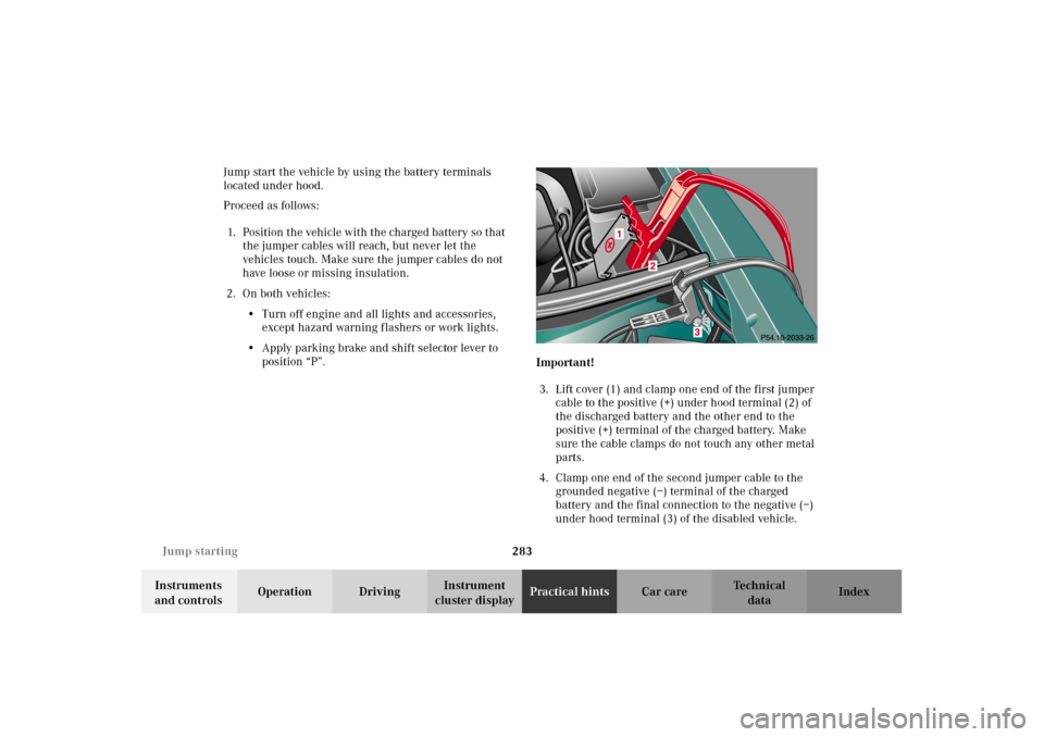
located under hood.
Proceed as follows:
1. Position the vehicle with the charged battery so that
the jumper cables will reach, but never let the
vehicles touch. Make sure the jumper cables do not
have loose or missing insulation.
2. On both vehicles:
•Turn off engine and all lights and accessories,
except hazard warning flashers or work lights.
•Apply parking brake and shift selector lever to
position “P”.
Important!
3. Lift cover (1) and clamp one end of the first jumper
cable to the positive (+) under hood terminal (2) of
the discharged battery and the other end to the
positive (+) terminal of the charged battery. Make
sure the cable clamps do not touch any other metal
parts.
4. Clamp one end of the second jumper cable to the
grounded negative (–) terminal of the charged
battery and the final connection to the negative (–)
under hood terminal (3) of the disabled vehicle.
W210.book Seite 283 Mittwoch, 30. Mai 2001 11:45 11
Page 297 of 350
294 Electronic main key
Technical
data Instruments
and controlsOperation DrivingInstrument
cluster displayPractical hintsCar care Index
Changing batteries in the electronic main key
1Transmit buttons
2Lamp for battery check and function control
Checking batteries
If one of the transmit buttons (1) is pressed, the battery
check lamp (2) lights up briefly – indicating that the
batteries are in order.
Change batteries if the battery check lamp (2) does not
light up briefly.Changing batteries
Move locking tab (3) in direction of right arrow and
remove mechanical key (4, left arrow).
P80.20-2201-26
1
2
P80.35-2029-26
4
3
W210.book Seite 294 Mittwoch, 30. Mai 2001 11:45 11