2002 MERCEDES-BENZ E430 turn signal
[x] Cancel search: turn signalPage 8 of 350

5 Contents
Vehicle careCleaning and care
of the vehicle .............................304
Power washer ..............................305
Tar stains .....................................305
Paintwork, painted body
components .................................305
Engine cleaning ..........................306
Vehicle washing .........................306
Ornamental moldings ................306
Headlamps, taillamps,
turn signal lenses ......................306
Cleaning the parktronic
system sensors ...........................307
Window cleaning /
glass sunroof ...............................307
Wiper blades ...............................307
Light alloy wheels ......................308
Instrument cluster .....................308
Steering wheel and
gear selector lever ......................308
Cup holder ...................................308
Seat belts .....................................308Headliner and shelf
below rear window .................... 308
Upholstery .................................. 309
Hard plastic trim items ............. 309
Plastic and rubber parts ........... 309
Technical dataSpare parts service ........................312
Warranty coverage .........................312
Identification labels ....................... 313
Layout of poly-V-belt drive ............ 315
Technical data ................................. 316
Fuels, coolants, lubricants
etc. - capacities ......................... 322
Engine oils ...................................... 324
Engine oil additives ...................... 324
Air conditioner refrigerant .......... 324
Brake fluid ...................................... 324
Premium unleaded gasoline ........ 325
Fuel requirements ........................ 325
Gasoline additives ......................... 326
Coolants .......................................... 326
Consumer information ................. 328
IndexIndex ................................................330
W210.book Seite 5 Mittwoch, 30. Mai 2001 11:45 11
Page 32 of 350

29 Central locking system
Technical
data Instruments
and controlsOperationDrivingInstrument
cluster displayPractical hints Car care Index Locking and unlocking with remote control
Unlocking:
Press transmit button Œ. All turn signal lamps blink
once to indicate that the vehicle is unlocked.
The remote control can be programmed for two kinds of
unlocking modes (see below):
Selective unlocking mode –
Press transmit button Œ once to unlock driver’s
door and fuel filler flap.
Press transmit button Πtwice to unlock all doors,
fuel filler flap, and trunk.
Global unlocking mode –
Press transmit button Πonce to unlock all doors,
fuel filler flap, and trunk.
Notes:
If the trunk was previously locked separately, it will
remain locked, see page 37.
The presently active unlocking mode (selective or
global) can only be determined by unlocking the vehicle
with the remote control (see below for changing mode).If within 40 seconds of unlocking with the remote
control, neither door nor trunk is opened, the electronic
key is not inserted in the steering lock, or the central
locking switch is not activated, the vehicle will
automatically lock.
Locking:
Press transmit button ‹ once. All turn signal lamps
blink three times to indicate that the vehicle is locked.
If the turn signal lamps do not blink, a door or trunk is
not closed properly.
Note:
If the vehicle cannot be locked or unlocked by pressing
the transmit button, then it may be necessary to change
the batteries in the electronic key (if ok, battery check
lamp in electronic key will light briefly when pressing
transmit button) or to synchronize the remote control,
see pages 294 and 296.
W210.book Seite 29 Mittwoch, 30. Mai 2001 11:45 11
Page 90 of 350

87 Instrument cluster
Technical
data Instruments
and controlsOperationDrivingInstrument
cluster displayPractical hints Car care Index 1Push buttons for intensity of instrument lamps, see
page 89
2Push button for resetting trip odometer, see
page 91, or to acknowledge a malfunction warning
message, see page 108
3Coolant temperature gauge, see page 90
4Fuel gauge with reserve and fuel cap placement
warning lamp, see page 236
5Outside temperature indicator, see page 90
6Left turn signal indicator lamp, see combination
switch on page 122
7Electronic stability program (ESP) warning lamp,
see page 2378Speedometer
9Trip odometer, see page 91 and 96
10Main odometer, see page 96
11Multifunction indicator, see page 92,
or FSS indicator, see page 114,
or engine oil level indicator, see page 117
12Right turn signal indicator lamp, see combination
switch on page 122
13Tachometer, see page 91
14Gear range indicator display, see page 196
15Clock
To set the time, see page 110
W210.book Seite 87 Mittwoch, 30. Mai 2001 11:45 11
Page 117 of 350

114 Flexible service system
Technical
data Instruments
and controlsOperationDrivingInstrument
cluster displayPractical hints Car care Index
Flexible service system (FSS)
(service indicator)
The FSS permits a flexible service schedule that is
directly related to the operating conditions of the
vehicle.
The symbol 9 or ½ appears together with a
message in the multifunction indicator prior to the next
suggested service.
Dep end in g on oper atin g c ond ition s t hr oughout t he year,
the next service is calculated and displayed in days or
distance remaining.The message is displayed for approximately 10 seconds
when turning the electronic key in steering lock to
position 2, or while driving when reaching the service
warning threshold.
The symbols and messages indicate the type of service
to be performed:
9Service A
½Service B
One of the following messages will appear in the display
(e.g. Service A):
“SERVICE A – IN xx DAYS”
“SERVICE A – IN xx MILES” (Canada: KM)
“SERVICE A – EXCEEDED BY xx DAYS”
“SERVICE A – EXCEEDED BY xx MILES” (Canada: KM)
“SERVICE A – DUE NOW”
The next service due date is displayed either in days or
in miles, depending on your driving style.
Once the suggested service term has passed, the symbol
and message appear for approximately 30 seconds and
a signal sounds every time when turning the electronic
key in steering lock to position 2.
10
0
406080
60
40
mph
20km/h
20100
120
140160
80
100
180
200
220
240 160 120 140
W210.book Seite 114 Mittwoch, 30. Mai 2001 11:45 11
Page 119 of 350

116 Flexible service system
Technical
data Instruments
and controlsOperationDrivingInstrument
cluster displayPractical hints Car care Index
Following a completed A or B service the Mercedes-
Benz Center sets the counter mileage to 10 000 miles
(Canada: 15 000 km).
The counter can also be set by any individual. To do so:
Turn the electronic key in steering lock to position 2.
To call up the trip odometer and main odometer, press
button è or ÿ on the multifunction steering
wheel until the display appears. See page 96.
Press button j or k until the FSS indicator
appears.
Press buttonJon the instrument cluster for
approximately 4 seconds.The multifunction display will show the question:
“DO YOU WANT TO RESET SERVICE INTERVAL?
CONFIRM BY PRESSING R”
Press button J on the instrument cluster again for
approximately 4 seconds, and hold until a signal
sounds. The message “SERVICE INTERVAL HAS BEEN
RESET” appears in the multifunction display.
The new service indicator is displayed with the reset
distance of 10 000 miles (Canada 15 000 km).
If the FSS counter was inadvertently reset, have a
Mercedes-Benz Center correct it.
However you choose to set your reference numbers, the
scheduled services as posted in the Service Booklet
must be followed to properly care for your vehicle.
W210.book Seite 116 Mittwoch, 30. Mai 2001 11:45 11
Page 125 of 350

122 Combination switch
Technical
data Instruments
and controlsOperationDrivingInstrument
cluster displayPractical hints Car care Index
Combination switch
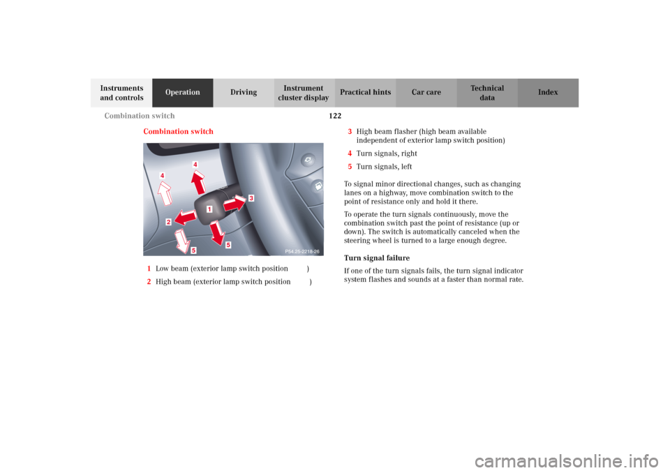
1Low beam (exterior lamp switch position B)
2High beam (exterior lamp switch position B)3High beam flasher (high beam available
independent of exterior lamp switch position)
4Turn signals, right
5Turn signals, left
To signal minor directional changes, such as changing
lanes on a highway, move combination switch to the
point of resistance only and hold it there.
To operate the turn signals continuously, move the
combination switch past the point of resistance (up or
down). The switch is automatically canceled when the
steering wheel is turned to a large enough degree.
Turn signal failure
If one of the turn signals fails, the turn signal indicator
system flashes and sounds at a faster than normal rate.
4
4
2
5
5
3
1
W210.book Seite 122 Mittwoch, 30. Mai 2001 11:45 11
Page 128 of 350

125 Hazard warning flasher
Technical
data Instruments
and controlsOperationDrivingInstrument
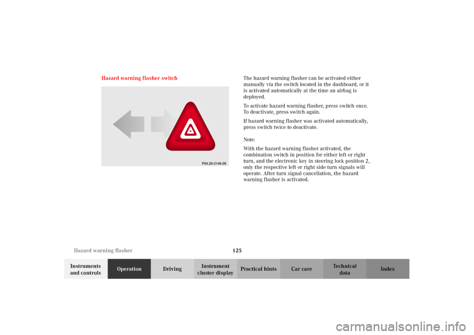
cluster displayPractical hints Car care Index Hazard warning flasher switchThe hazard warning flasher can be activated either
manually via the switch located in the dashboard, or it
is activated automatically at the time an airbag is
deployed.
To activate hazard warning flasher, press switch once.
To deactivate, press switch again.
If hazard warning flasher was activated automatically,
press switch twice to deactivate.
Note:
With the hazard warning flasher activated, the
combination switch in position for either left or right
turn, and the electronic key in steering lock position 2,
only the respective left or right side turn signals will
operate. After turn signal cancellation, the hazard
warning flasher is activated.
W210.book Seite 125 Mittwoch, 30. Mai 2001 11:45 11
Page 175 of 350

172 Garage door opener
Technical
data Instruments
and controlsOperationDrivingInstrument
cluster displayPractical hints Car care Index
Programming or reprogramming the integrated
remote control:
1. Turn electronic key in steering lock to position 1
or 2.
2. Hold the end of the hand-held transmitter of the
device you wish to train approximately 2 to 5 inches
(5 cm to 12 cm) away from the surface of the
integrated remote control located on the inside rear
view mirror, keeping the indicator lamp in view.
3. Using both hands, simultaneously push the hand-
held transmitter button and the desired integrated
remote control button. Do not release the buttons
until completing step 4.4. The indicator lamp on the integrated remote control
will flash, first slowly and then rapidly. When the
indicator lamp flashes rapidly, both buttons may be
released (the rapid flashing lamp indicates
successful programming of the new frequency
signal). To program the remaining two buttons,
follow steps 1 through 4.
Note:
If, after repeated attempts, you do not successfully
program the integrated remote control device to learn
the signal of the hand-held transmitter, the garage door
opener could be equipped with the “rolling code
feature”.
W210.book Seite 172 Mittwoch, 30. Mai 2001 11:45 11