Page 470 of 909
AUTOMATIC TRANSAXLE
K2–55
K2
Construction (System diagram)
.
1T 1Z 1W
1AA
2C 2Y
1S
1H2B 1K
1X
1M
1V
1N
2F
2J
2M
1F
1B
9
8
7
5
4
3
1
2
10
17
15
16
14
13
11
12
6
A6E5714W019
1 Intermediate sensor
2 VSS
3 Input/turbine speed sensor
4 Throttle position signal
5 Engine torque signal
6 TFT sensor
7TCM8TR switch
9 Pressure control solenoid
10 M range switch
11 Up switch
12 Down switch
13 Cruise control module
Page 472 of 909

AUTOMATIC TRANSAXLE
K2–57
K2
Line Pressure Control at Extremely Low Temperatures
•When the ATF temperature is approximately –30 °C {–22 °F} or below, the period when the pressure control
solenoid is ON (duty ratio) is set at 3 % to maintain line pressure at maximum regardless of the throttle opening
angle. Thus delay in clutch or brake operation due to high viscosity of ATF is prevented when the ATF
temperature is extremely low.
Pressure Control Solenoid Stop Control
•When the vehicle is stopped and the accelerator pedal is released, the operation (duty ratio) of the pressure
control solenoid is set at 3 %, regardless of the driving range. Due to this, AT noise is reduced when the vehicle
is stopped.
End Of Sie
FEEDBACK CONTROL DESCRIPTIONA6E571418901206Outline
Features
•During shift up with the accelerator pedal depressed, feedback control regulates the clutch pressure on the
engagement and release sides, according to the throttle opening angle and vehicle speed. It also uses past
gearshifts to optimize clutch pressure.
Note
•If the battery terminal is disconnected, feedback memory in the TCM will be erased, and thus gearshift
shock may increase. The shock, however, will decrease gradually as the vehicle is driven.
AMU0517S034
Page 474 of 909
AUTOMATIC TRANSAXLE
K2–59
K2
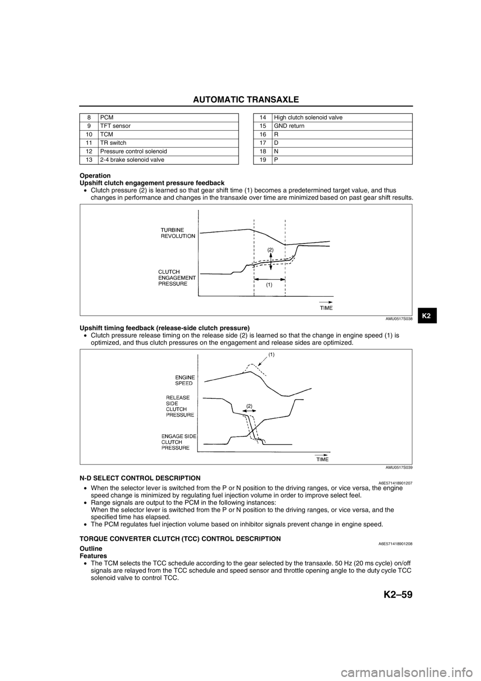
Operation
Upshift clutch engagement pressure feedback
•Clutch pressure (2) is learned so that gear shift time (1) becomes a predetermined target value, and thus
changes in performance and changes in the transaxle over time are minimized based on past gear shift results.
Upshift timing feedback (release-side clutch pressure)
•Clutch pressure release timing on the release side (2) is learned so that the change in engine speed (1) is
optimized, and thus clutch pressures on the engagement and release sides are optimized.
End Of SieN-D SELECT CONTROL DESCRIPTIONA6E571418901207•When the selector lever is switched from the P or N position to the driving ranges, or vice versa, the engine
speed change is minimized by regulating fuel injection volume in order to improve select feel.
•Range signals are output to the PCM in the following instances:
When the selector lever is switched from the P or N position to the driving ranges, or vice versa, and the
specified time has elapsed.
•The PCM regulates fuel injection volume based on inhibitor signals prevent change in engine speed.
End Of Sie
TORQUE CONVERTER CLUTCH (TCC) CONTROL DESCRIPTIONA6E571418901208Outline
Features
•The TCM selects the TCC schedule according to the gear selected by the transaxle. 50 Hz (20 ms cycle) on/off
signals are relayed from the TCC schedule and speed sensor and throttle opening angle to the duty cycle TCC
solenoid valve to control TCC.
8PCM
9 TFT sensor
10 TCM
11 TR switch
12 Pressure control solenoid
13 2-4 brake solenoid valve14 High clutch solenoid valve
15 GND return
16 R
17 D
18 N
19 P
AMU0517S038
AMU0517S039
Page 475 of 909
K2–60
AUTOMATIC TRANSAXLE
Construction (system diagram)
.
1T 1Z 1W
2B
1S 1M
1V
1N
2F
2J
2M
1F
1B
9
8
7
5
4
3
1
2
10
15
14
13
11
12
6
A6E5714W021
1 VSS
2 Input/turbine speed sensor
3 Engine speed signal
4 Throttle position signal
5 TCC signal
6PCM
7CAN
8 TFT sensor9TCM
10 TR switch
11 TCC solenoid valve
12 R
13 D
14 N
15 P
Page 476 of 909
AUTOMATIC TRANSAXLE
K2–61
K2
Operation
Torque converter clutch (TCC) release operation
•The TCM sends an OFF signal to TCC solenoid valve to release the TCC. In this condition, the TCC control
valve is pushed to the up side by spring force and line pressure, and torque converter pressure acts on the
torque converter front chamber, releasing the TCC from the converter cover.
AMU0517S041
Page 477 of 909
K2–62
AUTOMATIC TRANSAXLE
Torque converter clutch (TCC) engaging operation
•The TCM determines smooth TCC operation. It sends an ON signal to the TCC solenoid valve to push the TCC
control valve to the down side. Consequently, the hydraulic pressure applied to the torque converter front
chamber is drained through the TCC control valve, engaging torque converter clutch.
Coast TCC
•Even when the accelerator pedal is released in the TCC range at high speeds, the TCC remains engaged to
prevent repetition of TCC engagement/release by depressing/releasing the accelerator pedal, as well as
reducing shock during the operation.
AMU0517S042
Page 478 of 909
AUTOMATIC TRANSAXLE
K2–63
K2
Determination of Torque Converter Clutch (TCC) Cancellation
The TCC control is canceled when any of the following condition are met:
•Engine coolant temperature is low.
•ATF temperature is low.
•Brake switch is on (when depressing the brake pedal).
•Accelerator depressing speed and accelerator opening angle are above the set value.
•Engine speed signal is below the set value.
•Failure is in the TCC control system detected by diagnosis function.
End Of Sie
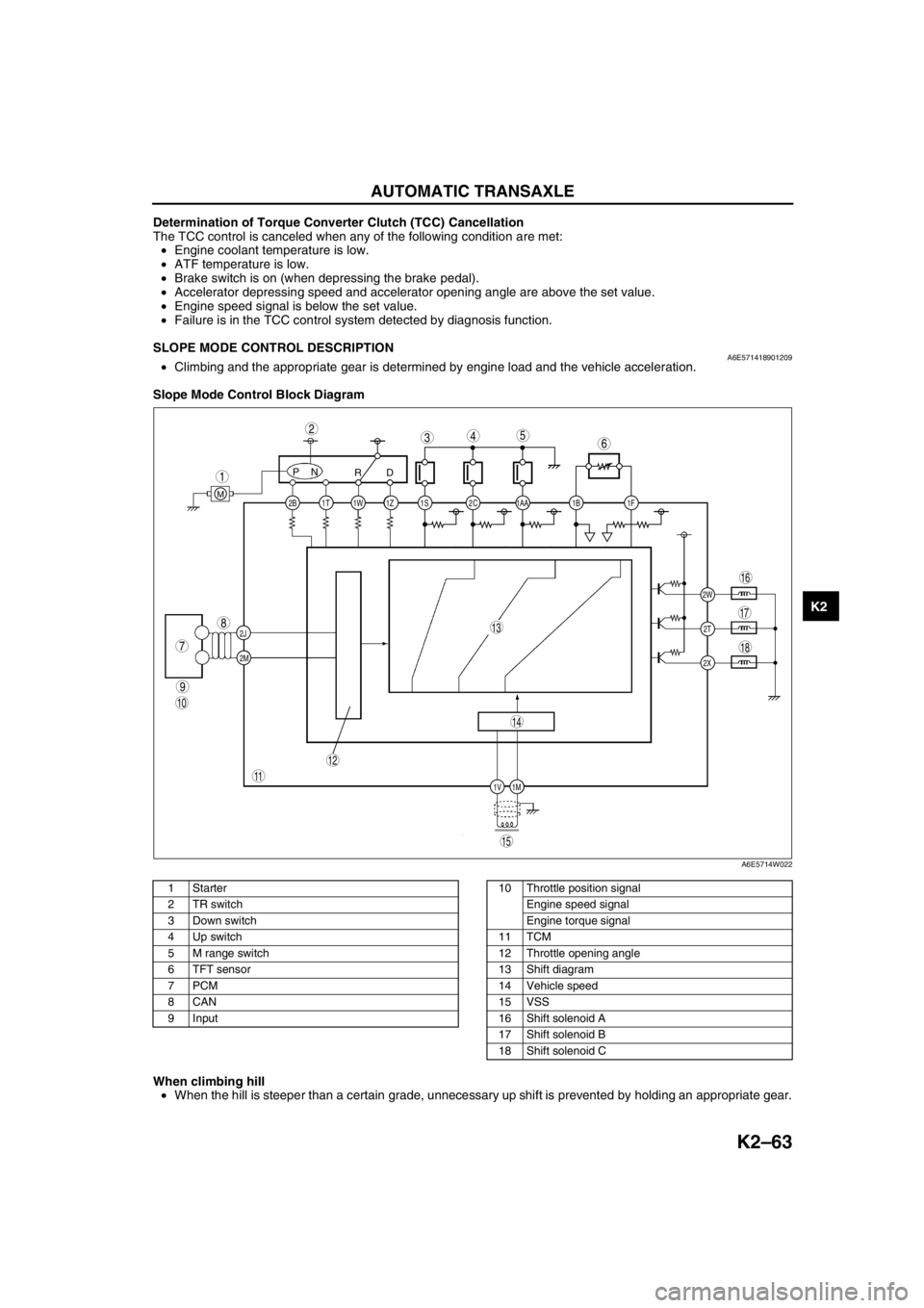
SLOPE MODE CONTROL DESCRIPTIONA6E571418901209•Climbing and the appropriate gear is determined by engine load and the vehicle acceleration.
Slope Mode Control Block Diagram
.
When climbing hill
•When the hill is steeper than a certain grade, unnecessary up shift is prevented by holding an appropriate gear.
End Of Sie
2C 2B
2J
2M1AA 1S 1T 1Z1W 1B 1F
2W
1M 1V2T
2X
PN
RD
M
9
8
7
543
1
2
10
18
17
15
16
14
13
11
12
6
A6E5714W022
1Starter
2 TR switch
3 Down switch
4 Up switch
5 M range switch
6 TFT sensor
7PCM
8CAN
9 Input10 Throttle position signal
Engine speed signal
Engine torque signal
11 TCM
12 Throttle opening angle
13 Shift diagram
14 Vehicle speed
15 VSS
16 Shift solenoid A
17 Shift solenoid B
18 Shift solenoid C
Page 479 of 909
K2–64
AUTOMATIC TRANSAXLE
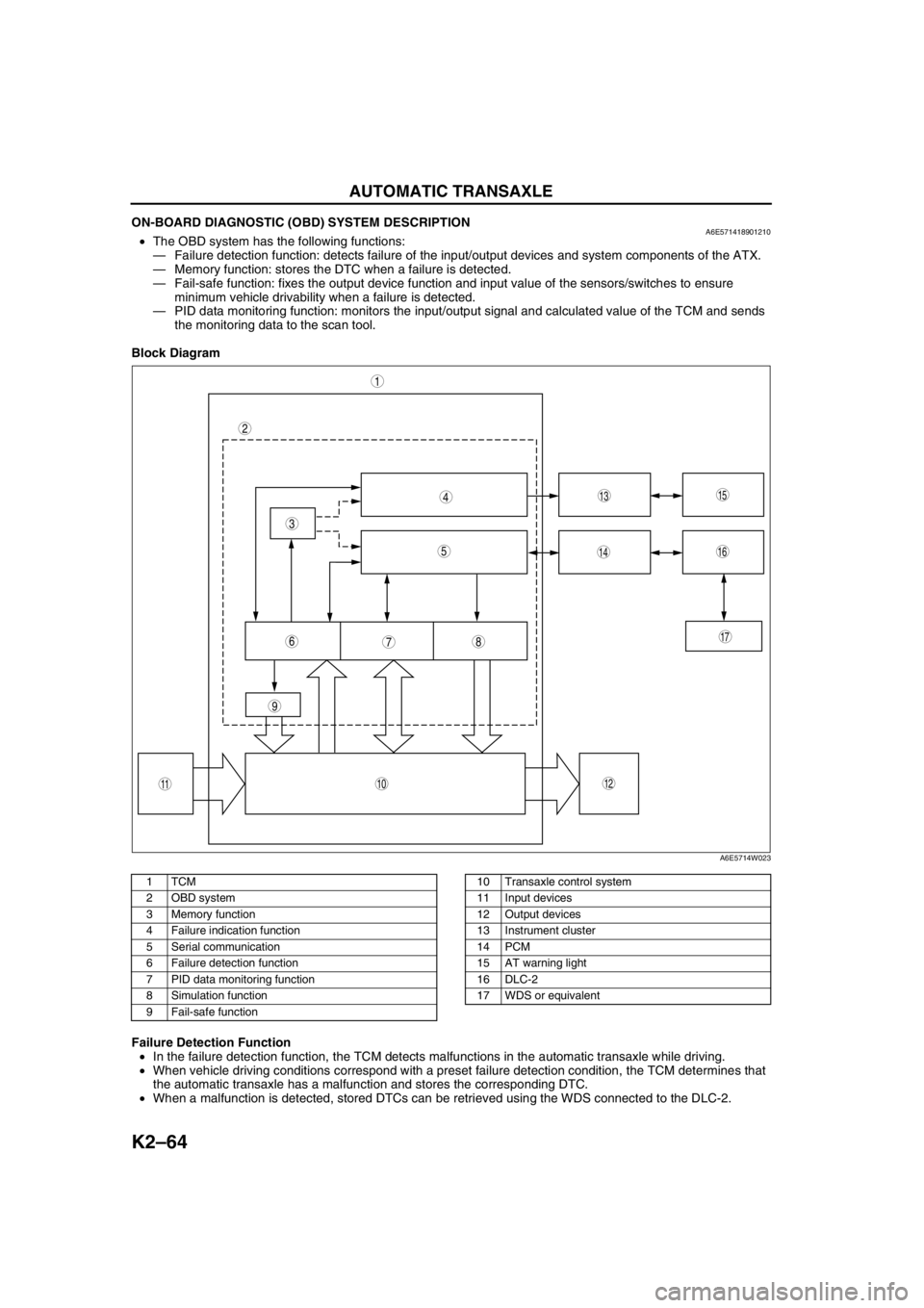
ON-BOARD DIAGNOSTIC (OBD) SYSTEM DESCRIPTIONA6E571418901210•The OBD system has the following functions:
—Failure detection function: detects failure of the input/output devices and system components of the ATX.
—Memory function: stores the DTC when a failure is detected.
—Fail-safe function: fixes the output device function and input value of the sensors/switches to ensure
minimum vehicle drivability when a failure is detected.
—PID data monitoring function: monitors the input/output signal and calculated value of the TCM and sends
the monitoring data to the scan tool.
Block Diagram
.
Failure Detection Function
•In the failure detection function, the TCM detects malfunctions in the automatic transaxle while driving.
•When vehicle driving conditions correspond with a preset failure detection condition, the TCM determines that
the automatic transaxle has a malfunction and stores the corresponding DTC.
•When a malfunction is detected, stored DTCs can be retrieved using the WDS connected to the DLC-2.
9
87
5
4
3
1
2
10
17
15
1614
13
1112
6
A6E5714W023
1TCM
2 OBD system
3 Memory function
4 Failure indication function
5 Serial communication
6 Failure detection function
7 PID data monitoring function
8 Simulation function
9 Fail-safe function10 Transaxle control system
11 Input devices
12 Output devices
13 Instrument cluster
14 PCM
15 AT warning light
16 DLC-2
17 WDS or equivalent


