2002 MAZDA 6 Tcm
[x] Cancel search: TcmPage 480 of 909

AUTOMATIC TRANSAXLE
K2–65
K2
Memory Function
•The memory function stores failure information detected in the failure detection function. Once failure
information is stored, the memory will not be cleared even when the ignition switch is turned off (LOCK
position) or the malfunction is repaired.
•The stored memory (failure information) can be cleared by using the WDS or disconnecting the negative
battery cable.
Failure Indication Function
•The failure indication function illuminates the AT warning lights when the failure detection function determines
there is a malfunction.
DTC Table
X : Available
CCM:Continuous monitor
Fail-safe Function
•In the fail-safe function, minimum vehicle drivability is obtained by changing the signals that are determined as
malfunctions by the failure detection function to the preset values, and limiting the TCM control.
DTC No. On-board diagnostic function MILAT warning
light
indicationDCMonitor
itemMemory
function
P0705 TR switch circuit malfunction (Power short circuit) X X 2 CCM X
P0706 TR switch circuit malfunction (Open/ground short circuit) X X 2 CCM X
P0711 TFT sensor malfunction (Stuck) X–2 CCM X
P0712 TFT sensor circuit malfunction (Short circuit) X X 2 CCM X
P0713 TFT sensor circuit malfunction (Open circuit) X X 2 CCM X
P0715 Input/turbine speed sensor circuit malfunction X X 2 CCM X
P0720 Vehicle speedometer sensor circuit malfunction X X 2 CCM X
P0740 TCC system X–2 CCM X
P0743 TCC solenoid valve malfunction (Open/short) X X 1 CCM X
P0748 Pressure control solenoid malfunction (Open/short)–X–CCM X
P0751 Shift solenoid A malfunction (Stuck off) X–2 CCM X
P0752 Shift solenoid A malfunction (Stuck on) X–2 CCM X
P0753 Shift solenoid A malfunction (Open/short) X X 1 CCM X
P0756 Shift solenoid B malfunction (Stuck off) X–2 CCM X
P0757 Shift solenoid B malfunction (Stuck on) X–2 CCM X
P0758 Shift solenoid B malfunction (Open/short) X X 1 CCM X
P0761 Shift solenoid C malfunction (Stuck off) X–2 CCM X
P0762 Shift solenoid C malfunction (Stuck on) X–2 CCM X
P0763 Shift solenoid C malfunction (Open/short) X X 1 CCM X
P0768 Reduction timing solenoid malfunction (Open/short)–X–CCM X
P0773 Neutral shift solenoid malfunction (Open/short)–X–CCM X
P0778 2-4 brake solenoid malfunction (Open/short)–X–CCM X
P0791 Intermediate sensor malfunction (Open/short) X X 2 CCM X
P0798 High clutch solenoid malfunction (Open/short)–X–CCM X
P1710 GND return malfunction–––Other X
U0073 CAN BUS OFF X X 1 CCM X
U0100 TCM cannot receive any signals from PCM X X 1 CCM X
DTC
No.On-board diagnostic function Detection condition Fail-safe TCC
P0705Transaxle range (TR) switch
circuit malfunction (power short
circuit)•Two or more range signals
are inputted from TR switch
for 5 seconds or more•TR switch priority
D > N > P > R
•Inhibits feedback control,
SLOPE mode, torque
reduction controlAvailable
P0706Transaxle range (TR) switch
circuit malfunction (open/ground
short circuit)•No range signal is inputted
from TR switch for 100
seconds or more•Inhibits feedback control,
SLOPE mode, torque
reduction controlAvailable
Page 481 of 909

K2–66
AUTOMATIC TRANSAXLE
P0711Transaxle fluid temperature (TFT)
sensor malfunction (stuck)•TFT sensor signal stays
outside normal temperature
range for 10 minute or more—Available
P0712Transaxle fluid temperature (TFT)
sensor circuit malfunction (short
circuit)•Signals form TFT sensor are
155 °C {311 °F} or greater
for 10 min.
•Inhibits feedback control
•Engine coolant temperature
signal are used for shifting.Available
P0713Transaxle fluid temperature (TFT)
sensor circuit malfunction (open
circuit)•Vehicle speed is 20 km/h
{12.4 mph} or greater, and
signals from TFT sensor are
–30 °C {–22 °F} or less for
150 seconds or moreAvailable
P0715Input/turbine speed sensor circuit
malfunction•Input/turbine speed sensor
is 600 rpm or less while
engine speed is 1500 rpm or
greater and vehicle speed is
40 km/h {24.8 mph} or
greater in D ranges.•Inhibits shift control Available
P0720Vehicle speedometer sensor
circuit malfunction•Parking gear rotation
detected by VSS is 150 rpm
or less while intermediate
sensor 1400 rpm or greater
in D range for 2 second or
more.•Inhibits SLOPE mode,
feedback control, torque
reduction controlAvailable
P0740Torque converter clutch (TCC)
system•RPM difference between
crankshaft (engine speed
signal) and reverse clutch
drum (input/turbine speed
sensor signal) exceeds the
pre-programmed value—Available
P0743Torque converter clutch (TCC)
solenoid valve malfunction (open/
short)•Open or short in torque
converter clutch solenoid
valve circuit (Voltage
different from on/off signal
relayed by CPU in TCM is
detected while TCM is
monitoring solenoid output
voltage.)•Stops driving of TCC
solenoid valve (OFF)Inhibition
P0748Pressure control solenoid
malfunction (open/short)•Open or short in pressure
control solenoid circuit
(Voltage different from on/off
signal relayed by CPU in
TCM is detected while TCM
is monitoring solenoid
output voltage.)•Stops driving of pressure
control solenoid, 2-4 brake
solenoid valve, and high
clutch solenoid valve (OFF)
•Inhibit feedback control.Available
P0751Shift solenoid A malfunction
(stuck off)•Difference between actual
gear ratio and gear ratio set
in TCM is large—Available
P0752Shift solenoid A malfunction
(stuck on)•Difference between actual
gear ratio and gear ratio set
in TCM is large—Available
P0753Shift solenoid A malfunction
(open/short)•Open or short in shift
solenoid A circuit (Voltage
different from on/off signal
relayed by CPU in TCM is
detected while TCM is
monitoring solenoid output
voltage.)•Stops driving all ON/OFF
type solenoids (OFF) and
TCC solenoid valve (OFF)Inhibition
P0756Shift solenoid B malfunction
(stuck off)•Difference between actual
gear ratio and gear ratio set
in TCM is large—Available
P0757Shift solenoid B malfunction
(stuck on)•Difference between actual
gear ratio and gear ratio set
in TCM is large—Available DTC
No.On-board diagnostic function Detection condition Fail-safe TCC
Page 482 of 909

AUTOMATIC TRANSAXLE
K2–67
K2
P0758Shift solenoid B malfunction
(open/short)•Open or short in shift
solenoid B circuit (Voltage
different from on/off signal
relayed by CPU in TCM is
detected while TCM is
monitoring solenoid output
voltage.)•Stops driving all ON/OFF
type solenoids (OFF) and
TCC solenoid valve (OFF)Inhibition
P0761Shift solenoid C malfunction
(stuck off)•Difference between actual
gear ratio and gear ratio set
in TCM is large—Available
P0762Shift solenoid C malfunction
(stuck on)•Difference between actual
gear ratio and gear ratio set
in TCM is large—Available
P0763Shift solenoid C malfunction
(open/short)•Open or short in shift
solenoid C circuit (Voltage
different from on/off signal
relayed by CPU in TCM is
detected while TCM is
monitoring solenoid output
voltage.)•Stops driving all ON/OFF
type solenoids (OFF) and
TCC solenoid valve (OFF)Inhibition
P0768Reduction timing solenoid valve
malfunction (open/short)•Open or short in reduction
timing solenoid valve circuit
(Voltage different from on/off
signal relayed by CPU in
TCM is detected while TCM
is monitoring solenoid
output voltage.)•Stops driving of reduction
timing solenoid valve (OFF)Available
P0773Neutral shift solenoid valve
malfunction (open/short)•Open or short in neutral shift
solenoid valve circuit
(Voltage different from on/off
signal relayed by CPU in
TCM is detected while TCM
is monitoring solenoid
output voltage.)•Stops driving of neutral shift
solenoid valve (OFF)Available
P07782-4 brake solenoid valve
malfunction (open/short)•Open or short in 2-4 brake
solenoid valve circuit
(Voltage different from on/off
signal relayed by CPU in
TCM is detected while TCM
is monitoring solenoid
output voltage.)•Stops driving of pressure
control solenoid, 2-4 brake
solenoid valve, and high
clutch solenoid valve (OFF)
•Inhibit feedback control.Available
P0791Intermediate sensor malfunction
(open/short)•Rotation speed of output
gear (intermediate sensor)
is low when vehicle speed
and engine speed exceed
the pre programmed value•Inhibit feedback control
•Inhibits torque reduction
controlAvailable
P0798High clutch solenoid valve
malfunction (open/short)•Open or short in high clutch
solenoid valve circuit
(Voltage different from on/off
signal relayed by CPU in
TCM is detected while TCM
is monitoring solenoid
output voltage.)•Stops driving of pressure
control solenoid, 2-4 brake
solenoid valve, and high
clutch solenoid valve (OFF)
•Inhibit feedback control.Available
P1710 GND return malfunction•TCM detects open in GND
return signal of solenoid.—Available
U0073 CAN BUS OFF•CAN controller damaged.•Throttle valve opening angle
is fixed (4/8) at the time in
order to determine shift
•Maximizes line pressureInhibition
U0100TCM cannot receive any signals
from PCM•TCM cannot receive any
signals from PCM DTC
No.On-board diagnostic function Detection condition Fail-safe TCC
Page 483 of 909

K2–68
AUTOMATIC TRANSAXLE
Parameter Identification (PID) Access
Monitor item table
End Of Sie
Display on the
testerDefinitionUnit/
ConditionTCM
terminal
2-4 B Duty 2-4 brake solenoid valve control signal in TCM ON/OFF 2V
BOO Brake switch ON/OFF 1U
DWN_SW Down switch ON/OFF 1S
GEAR Calculated gear range in TCM1ST/2ND/
3RD/4TH/5TH–
H/C Duty High clutch solenoid valve control signal in TCM % 2U
LPS Pressure control solenoid control signal in TCM % 2Y
MNL_SW M range switch ON/OFF 1AA
NSFT TIM Neutral shift solenoid valve control signal in TCM ON/OFF 2D
OSS Intermediate sensor rpm 1K, 1X
PNP TR switch (P/N position switch) ON/OFF–
RDCN TIM Reduction timing solenoid valve control signal in TCM ON/OFF 2G
RPM Engine speed rpm–
SSA/SS1 Shift solenoid A control signal in TCM ON/OFF–
SSB/SS2 Shift solenoid B control signal in TCM ON/OFF–
SSC/SS3 Shift solenoid C control signal in TCM ON/OFF–
TCCC TCC solenoid valve control signal in TCM % 2S
TCIL AT warning light control signal in TCM ON/OFF 1E
TFT ATF temperature°C1B, 1F
TFTV ATF temperature signal voltage V 1B, 1F
THOP Throttle position %–
TRD Tr switch (D range switch) ON/OFF 1Z
TRR TR switch (R position switch) ON/OFF 1W
TSS Input/turbine speed sensor rpm 1N, 2F
UP_SW Up switch ON/OFF 2C
VPWR Battery voltage V 1P
VSS Vehicle speed km/h 1V, 1M
Page 486 of 909

LOCATION INDEX
K2–71
K2
End Of Sie
1 Automatic transaxle fluid (ATF)
(See K2–78 AUTOMATIC TRANSAXLE FLUID
(ATF) INSPECTION)
(See K2–80 AUTOMATIC TRANSAXLE FLUID
(ATF) REPLACEMENT)
2 Transaxle range (TR) switch
(See K2–80 TRANSAXLE RANGE (TR) SWITCH
INSPECTION)
(See K2–81 TRANSAXLE RANGE (TR) SWITCH
REMOVAL/INSTALLATION)
(See K2–83 TRANSAXLE RANGE (TR) SWITCH
ADJUSTMENT)
3 Transaxle fluid temperature (TFT) sensor
(See K2–84 TRANSAXLE FLUID TEMPERATURE
(TFT) SENSOR INSPECTION)
(See K2–85 TRANSAXLE FLUID TEMPERATURE
(TFT) SENSOR REMOVAL/INSTALLATION)
4 Input/turbine speed sensor
(See K2–85 INPUT/TURBINE SPEED SENSOR
INSPECTION)
(See K2–86 INPUT/TURBINE SPEED SENSOR
REMOVAL/INSTALLATION)
5 Intermediate sensor
(See K2–86 INTERMEDIATE SENSOR
INSPECTION)
(See K2–86 INTERMEDIATE SENSOR REMOVAL/
INSTALLATION)
6 Vehicle speedometer sensor (VSS)
(See K2–87 VEHICLE SPEEDOMETER SENSOR
(VSS) INSPECTION)
(See K2–87 VEHICLE SPEEDOMETER SENSOR
(VSS) REMOVAL/INSTALLATION)
7 Solenoid valve
(See K2–88 SOLENOID VALVE INSPECTION)
(See K2–90 SOLENOID VALVE REMOVAL/
INSTALLATION)
8TCM
(See K2–90 TCM INSPECTION)
(See K2–96 TCM REMOVAL/INSTALLATION)9 Transfer oil
(See K2–114 TRANSFER OIL INSPECTION)
(See K2–114 TRANSFER OIL REPLACEMENT)
10 Automatic transaxle
(See K2–99 AUTOMATIC TRANSAXLE AND
TRANSFER REMOVAL/INSTALLATION)
11 Transfer
(See K2–115 TRANSFER REMOVAL/
INSTALLATION)
(See K2–116 BREATHER PLUG REMOVAL/
INSTALLATION)
12 Oil seal
(See K2–104 OIL SEAL REMOVAL/
INSTALLATION)
13 Control valve body
(See K2–105 CONTROL VALVE BODY REMOVAL/
INSTALLATION)
14 Oil cooler
(See K2–106 OIL COOLER FLUSHING)
(See K2–108 OIL COOLER REMOVAL/
INSTALLATION)
(See K2–110 OIL COOLER DISASSEMBLY/
ASSEMBLY)
15 Drive plate
(See K2–112 DRIVE PLATE REMOVAL/
INSTALLATION)
16 Selector lever
(See K2–117 SELECTOR LEVER INSPECTION)
(See K2–117 SELECTOR LEVER COMPONENT
INSPECTION)
(See K2–119 SELECTOR LEVER REMOVAL/
INSTALLATION)
(See K2–122 SELECTOR LEVER DISASSEMBLY/
ASSEMBLY)
17 Selector cable
(See K2–118 SELECTOR CABLE ADJUSTMENT)
Page 491 of 909

K2–76
AUTOMATIC TRANSAXLE
D Range Test
Note
•The NORMAL mode and SLOPE mode are automatically selected by the TCM in D range. The TCM shifts
to SLOPE mode when the upgrade is approx. 5 % or more, and shifts to NORMAL mode when the
upgrade is approx. 3 % or less.
1. Perform road test preparation. (See K2–75 Road Test Preparation.)
2. Shift the selector lever to D range.
3. Accelerate the vehicle with half and WOT, then verify that 1→2, 2→3, 3→4, and 4→5 upshifts and downshifts
are obtained. The shift points must be as shown in the table below.
•If not as specified, inspect the TCM and ATX. (See K2–183 AUTOMATIC TRANSAXLE SYMPTOM
TROUBLESHOOTING.)
4. Drive the vehicle in 5GR, 4GR, 3GR, and 2GR and verify that kickdown occurs for 5→4, 4→3, 3→2, and 2→1
downshifts, and that the shift points are as shown in the table below.
•If not as specified, inspect the TCM and ATX. (See K2–183 AUTOMATIC TRANSAXLE SYMPTOM
TROUBLESHOOTING.)
5. Decelerate the vehicle and verify that engine braking effect is felt in 5GR.
•If not as specified, inspect the TCM and ATX. (See K2–183 AUTOMATIC TRANSAXLE SYMPTOM
TROUBLESHOOTING.)
6. Drive the vehicle and verify that TCC operation is obtained. The operation points must be as shown in the table
below.
•If not as specified, inspect the TCM and ATX. (See K2–183 AUTOMATIC TRANSAXLE SYMPTOM
TROUBLESHOOTING.)
Note
•The shift solenoid electrical ON-OFF pattern is this chart describes the stabilized condition before and
after shift control. The pattern may oscillate between ON and OFF momentarily while shifting-up or down.
This is normal.
Vehicle speed at shift point table
Range ModeThrottle
conditionShiftVehicle speed
(km/h {mph})Turbine speed
(rpm)
DNORMALWide open
throttleD
1→D250—56 {31—34} 5,800—6,450
D
2→D389—97 {56—60} 5,800—6,250
D
3→D4139—149 {87—92} 5,800—6,150
TCC ON (D
4)
127—137 {79—84} 3,650—3,850
D
4→D5195—205 {121—127} 5,550—5,800
TCC ON (D
5)
195—205 {121—127} 4,100—4,250
Half throttleD
1→D225—34 {16—21} 2,850—3,950
D
2→D345—62 {28—38} 2,900—4,000
D
3→D472—99 {45—61} 3,000—4,100
TCC ON (D
4)
93—121 {58—75} 2,650—3,450
D
4→D5124—149 {77—92} 3,550—4,200
TCC ON (D
5)
124—149 {77—92} 2,600—3,100
Closed throttle
positionD
5→D455—61 {35—37} 1,1500—1,250
D
4→D323—29 {15—17} 700—800
D
3→D17—13 {5—8} 300—500
KickdownD
5→D4185—195 {115—120} 3,850—4,050
D
4→D3127—137 {79—84} 3,650—3,850
D
3→D277—85 {48—52} 3,200—3,500
D
2→D137—43 {23—26} 2,400—2,750
Page 492 of 909

AUTOMATIC TRANSAXLE
K2–77
K2
M Range Test
1. Perform road test preparation. (See K2–75 Road Test Preparation.)
2. Shift the selector lever to M range.
3. Verify that 1→2, 2→3, 3→4, and 4→5 upshifts and 5→4, 4→3, 3→2, and 2→1 downshifts are obtained by
manual shifting of the selector lever forward and back. The shift points must be as shown in the table below.
•If not as specified, inspect the TCM and ATX. (See K2–183 AUTOMATIC TRANSAXLE SYMPTOM
TROUBLESHOOTING.)
4. Decelerate the vehicle and verify that 5→4, 4→3, 3→1, and 2→1 downshifts are obtained. The shift points
must be as shown in the table below.
•If not as specified, inspect the TCM and ATX.(See K2–183 AUTOMATIC TRANSAXLE SYMPTOM
TROUBLESHOOTING.)
5. Decelerate the vehicle and verify that engine braking effect is felt in all gears.
•If not as specified, inspect the TCM and ATX. (See K2–183 AUTOMATIC TRANSAXLE SYMPTOM
TROUBLESHOOTING.)
6. Drive the vehicle and verify that TCC operation is obtained in 5GR. The operation points must be as shown in
the table below.
•If not as specified, inspect the TCM and ATX. (See K2–183 AUTOMATIC TRANSAXLE SYMPTOM
TROUBLESHOOTING.)
Vehicle speed at shift point table
Noise and Vibration Test
1. Drive the vehicle and listen closely for any noise or vibration. The torque converter, drive shaft, and differential
can be sources of noise and vibration if they are not functioning properly. Inspect these when searching for
sources of noise and vibration.
P Position Test
1. Shift into P position on a gentle slope. Release the brake, and verify that the vehicle does not roll.
•If the vehicle rolls, inspect the ATX. (See K2–183 AUTOMATIC TRANSAXLE SYMPTOM
TROUBLESHOOTING.)
Range ModeThrottle
conditionShiftVehicle speed
(km/h {mph})Turbine speed
(rpm)
MManualHalf throttleTCC ON (M
5)
106—129 {66—79} 2,200—2,600
All roundM
5→M430—36 {19—22} 650—700
M
4→M323—29 {15—17} 650—800
M
2→M14—10 {3—6} 300—600
M
3→M14—10 {3—6} 200—400
Page 495 of 909
K2–80
AUTOMATIC TRANSAXLE
AUTOMATIC TRANSAXLE FLUID (ATF) REPLACEMENTA6E571419001202
Warning
•When the transaxle and ATF are hot, they can badly burn you. Turn off the engine and wait until
they are cool before changing the ATF.
1. Remove the oil dipstick.
2. Remove the oil drain plug and washer.
3. Drain the ATF into a container.
4. Install a new washer and the drain plug.
Tightening torque
39—54 N·m {3.9—5.6 kgf·m, 29—40 ft·lbf}
5. Add the specified type of ATF through the oil filler
tube, until ATF level reaches lower notch of
dipstick.
ATF type
ATF M-III or equivalent (e.g. Dexron
®III)
Capacity (Approximate quantity)
8.3 L {8.8 US qt, 7.3 Imp qt}
6. Verify that the ATF level is in the HOT (65 °C {149 °F}) range.
•Add ATF to the specified level as necessary.
End Of Sie
TRANSAXLE RANGE (TR) SWITCH INSPECTIONA6E571419440201
Note
•Input signals of the TR switch can be inspected with a WDS or equivalent. (See K2–90 TCM
INSPECTION.)
Inspection of Operation
1. Verify that the starter operates only with the ignition switch at the START position and the selector lever in P
and N positions.
•If not as specified, inspect for continuity at the TR switch. (See K2–80 Inspection of Continuity.)
2. Verify that the back-up lights illuminate when shifted to R position with the ignition switch at the ON position.
•If not as specified, inspect for continuity at the TR switch.
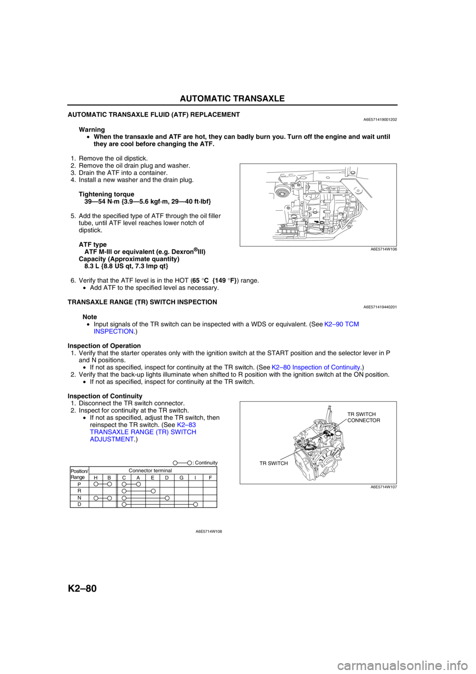
Inspection of Continuity
1. Disconnect the TR switch connector.
2. Inspect for continuity at the TR switch.
•If not as specified, adjust the TR switch, then
reinspect the TR switch. (See K2–83
TRANSAXLE RANGE (TR) SWITCH
ADJUSTMENT.)
A6E5714W106
TR SWITCHTR SWITCH
CONNECTOR
A6E5714W107
Position/
Range
H
P
R
N
DBCAEDGI FConnector terminal: Continuity
A6E5714W108