2002 MAZDA 6 PCM HARNESS SIDE CONNECTOR
[x] Cancel search: PCM HARNESS SIDE CONNECTORPage 222 of 909

F2–70
CONTROL SYSTEM
IDLE SWITCH INSPECTIONA6E404041600201
Note
•Perform the following test only when directed.
1. Verify that the accelerator position sensor is normal.
2. Visually inspect all accelerator pedal components for looseness.
3. Verify that the idle switch is installed to the accelerator pedal properly.
4. Verify that the power circuit voltage.
(1) Verify that the voltage between the PCM terminals 90 (power circuit) and 91(GND circuit) is 4.75—5.25 V.
Note
•Voltage at the PCM terminal 10 may deviate when the power circuit voltage is abnormal.
5. Verify that the voltage at the PCM terminal 31
(idle signal) is 1 V or less with the accelerator
pedal fully released.
6. Depress the accelerator pedal gradually and hold
the pedal when the PCM terminal 31 voltage
changes to approximately 10 V.
7. Verify that the voltage between the PCM
terminals 10 (accelerator position detection
signal) and 91 is within the specification.
•If the circuit is okay, replace the idle switch.
Specification
0.85—1.15 V (Target value: 1.0 V)
Circuit Open/Short Inspection
1. Inspect for open/short circuit in the following
wiring harnesses.
•If there is open/short circuit, repair or replace
wiring harnesses.
Open circuit
•Signal circuit
—Idle switch terminal A and PCM terminal 31
•GND circuit
—Idle switch terminal B and GND
Short circuit
•Signal circuit
—Idle switch terminal A and PCM terminal 31 to
GND
End Of Sie
ACCELERATOR POSITION SENSOR
IDLE SWITCHPCM B
A
C
D
A
B31 10
90
88
91
A6E40702037
IDLE SWITCH
HARNESS SIDE CONNECTOR
A
B
A6E40702038
Page 224 of 909

F2–72
CONTROL SYSTEM
ACCELERATOR POSITION SENSOR INSPECTIONA6E404041602201
Note
•Perform the following test only when directed.
1. Visually inspect all accelerator pedal components for looseness.
2. Verify that the accelerator position sensor is installed to the accelerator pedal properly.
3. Verify the power circuit voltage.
(1) Verify that the voltage between the PCM terminal 90 (power circuit) and 91 (GND circuit) is 4.75—5.25 V.
Note
•Voltage at the PCM terminal 10 may deviate when the power circuit voltage is abnormal.
4. Verify that the voltage between the PCM
terminals 10 (accelerator position detection
signal) and 91 is as shown below according to the
accelerator pedal conditions.
•If the circuit is okay, replace the accelerator
position sensor.
Specification
Circuit Open/Short Inspection
1. Inspect for open/short circuit in the following
wiring harnesses.
•If there is open/short circuit, repair or replace
wiring harnesses.
Open circuit
•Power circuit
—Accelerator position sensor terminal A and
PCM terminal 90
•Signal circuit
—Accelerator position sensor terminal B and
PCM terminal 10
—Accelerator position sensor terminal C and
PCM terminal 88
•GND circuit
—Accelerator position sensor terminal D and PCM terminal 91
Short circuit
•Power circuit
—Accelerator position sensor terminal A and PCM terminal 90 to GND
•Signal circuit
—Accelerator position sensor terminal B and PCM terminal 10 to power circuit
—Accelerator position sensor terminal B and PCM terminal 10 to GND
—Accelerator position sensor terminal C and PCM terminal 88 to power circuit
—Accelerator position sensor terminal C and PCM terminal 88 to GND
End Of Sie
Accelerator pedal
conditionOutput voltage (V)
Fully released 0.45—0.75 (Target value: 0.6)
Gradually depressed Increases linearly
Fully depressed 3.35—4.03 (Target value: 3.6)
ACCELERATOR POSITION SENSOR
PCM
B
A
C
D10
90
88
91
A6E40702041
ACCELERATOR POSITION SENSOR
HARNESS SIDE CONNECTOR
A B
C D
A6E40702042
Page 226 of 909

F2–74
CONTROL SYSTEM
MASS AIR FLOW (MAF)/INTAKE AIR TEMPERATURE (IAT) SENSOR INSPECTIONA6E404013210201
Note
•Perform the following test only when directed.
•Perform “MAF Correction” after replacing the MAF/IAT sensor. (See F2–35 MAF Correction.)
MAF Sensor Voltage Inspection
1. Turn the engine switch to ON.
2. Monitor the MAF PID using the WDS or equivalent.
•If not as specified, perform the “Circuit Open/Short Inspection”.
MAF PID
0.0—1.0 V
3. Start the engine and warm up the engine completely.
4. Monitor the MAF PID using the WDS or equivalent at idle.
•If not as specified, perform the “Circuit Open/Short Inspection”.
MAF PID
1.5—2.1 V
MAF Sensor CIrcuit Open/Short Inspection
1. Inspect for open/short circuit in the following
wiring harnesses.
•If there is open/short circuit, repair or replace
wiring harnesses.
Open circuit
•Power circuit
—MAF/IAT sensor terminal A and PCM control
relay terminal C
•Signal circuit
—MAF/IAT sensor terminal C and PCM terminal
9
•GND circuit
—MAF/IAT sensor terminal B and PCM terminal 14
Short circuit
•Power circuit
—MAF/IAT sensor terminal A and PCM control relay terminal C to GND
•Signal circuit
—MAF/IAT sensor terminal C and PCM terminal 9 to power circuit
—MAF/IAT sensor terminal C and PCM terminal 9 to GND
MAF/IAT SENSOR
HARNESS SIDE CONNECTOR
A
B
C
D E
A6E40702043
Page 230 of 909

F2–78
CONTROL SYSTEM
BOOST SENSOR INSPECTIONA6E404013214201
Note
•Perform the following test only when directed.
Visual Inspection
1. Inspect the boost sensor for damage and cracks.
•If not as specified, replace the boost sensor.
2. Inspect vacuum hose for improper routing, kinks or leakage.
•If there is any malfunction, repair or replace suspected hose.
Voltage Inspection
1. Turn the engine switch to ON.
2. Monitor the MAP PID using the WDS or equivalent.
•If not as specified, perform the “Circuit Open/Short Inspection”.
MAP PID
2.1—2.5 V
3. Start the engine and warm up the engine completely.
4. Monitor the MAP PID using the WDS or equivalent at idle.
•If not as specified, perform the “Circuit Open/Short Inspection”.
MAP PID
2.1—2.5 V
Circuit Open/Short Inspection
1. Inspect for open/short circuit in the following
wiring harnesses.
•If there is open/short circuit, repair or replace
wiring harnesses.
Open circuit
•Power circuit
—Boost sensor terminal C and PCM terminal 90
•Signal circuit
—Boost sensor terminal B and PCM terminal 36
•GND circuit
—Boost sensor terminal A and PCM terminal 91
Short circuit
•Power circuit
—Boost sensor terminal C and PCM terminal 90 to GND
•Signal circuit
—Boost sensor terminal B and PCM terminal 36 to power circuit
—Boost sensor terminal B and PCM terminal 36 to GND
End Of Sie
BOOST SENSOR
HARNESS SIDE CONNECTOR
A
B C
A6E40702048
Page 231 of 909

CONTROL SYSTEM
F2–79
F2
FUEL PRESSURE SENSOR INSPECTIONA6E404013015201
Note
•Perform the following test only when directed.
Voltage Inspection
1. Start the engine and warm up the engine completely.
2. Measure the voltage between fuel pressure sensor terminals A and B using a voltmeter at idle.
•If not as specified, perform the “Circuit Open/Short Inspection”.
—If there is no open/short circuit, replace the common rail.
Specification
1.4—1.7 V
3. Turn off the engine and wait three minutes.
4. Turn the engine switch to ON.
5. Measure the voltage between fuel pressure
sensor terminals A and B using a voltmeter.
•If not as specified, perform the “Circuit Open/
Short Inspection”.
—If there is no open/short circuit, replace
the common rail.
Specification
0.9—1.1 V
CIrcuit Open/Short Inspection
1. Inspect for open/short circuit in the following
wiring harnesses.
•If there is open/short circuit, repair or replace wiring harnesses.
Open circuit
•Power circuit
—Fuel pressure sensor terminal C and PCM terminal 90
•Signal circuit
—Fuel pressure sensor terminal B and PCM terminal 61
•GND circuit
—Fuel pressure sensor terminal A and PCM terminal 91
Short circuit
•Power circuit
—Fuel pressure sensor terminal C and PCM terminal 90 to GND
•Signal circuit
—Fuel pressure sensor terminal B and PCM terminal 61 to power circuit
—Fuel pressure sensor terminal B and PCM terminal 61 to GND
End Of Sie
FUEL PRESSURE SENSOR
HARNESS SIDE CONNECTOR
A
B C
A6E40702049
Page 242 of 909

F2–90
ON-BOARD DIAGNOSTIC
DTC P0091A6E407001082203
Diagnostic procedure
DTC P0091 Suction control valve circuit low input
DETECTION
CONDITION•PCM monitors input voltage from suction control valve while engine is running. If input voltage from suction
control valve does not change from off to on, PCM determines suction control valve circuit low input.
POSSIBLE
CAUSE•Suction control valve malfunction
•Connector or terminal malfunction
•Short to GND in wiring between suction control valve terminal A and PCM terminal 93
•Short to GND in wiring between suction control valve terminal B and PCM terminal 94
•Open circuit in wiring between suction control valve terminal A and PCM terminal 93
•Open circuit in wiring between suction control valve terminal B and PCM terminal 94
•PCM malfunction
STEP INSPECTION ACTION
1VERIFY RELATED REPAIR INFORMATION
AVAILABILITY
•Check for related Service Information
availability.
•Is any related repair information available?Yes Perform repair or diagnosis according to available Service
Information.
•If vehicle is not repaired, go to next step.
No Go to next step.
A
B93
94
BA SUCTION CONTROL VALVE
HARNESS SIDE CONNECTOR
94
93PCM
HARNESS SIDE CONNECTORPCM
SUCTION CONTROL VALVE
5
4
36
2
2
365
Page 244 of 909
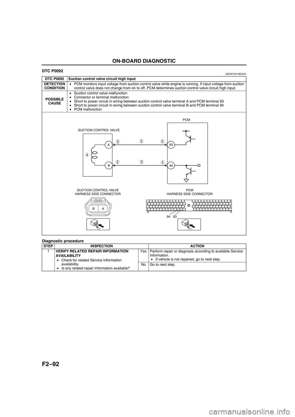
F2–92
ON-BOARD DIAGNOSTIC
DTC P0092A6E407001082204
Diagnostic procedure
DTC P0092 Suction control valve circuit high input
DETECTION
CONDITION•PCM monitors input voltage from suction control valve while engine is running. If input voltage from suction
control valve does not change from on to off, PCM determines suction control valve circuit high input.
POSSIBLE
CAUSE•Suction control valve malfunction
•Connector or terminal malfunction
•Short to power circuit in wiring between suction control valve terminal A and PCM terminal 93
•Short to power circuit in wiring between suction control valve terminal B and PCM terminal 94
•PCM malfunction
STEP INSPECTION ACTION
1VERIFY RELATED REPAIR INFORMATION
AVAILABILITY
•Check for related Service Information
availability.
•Is any related repair information available?Yes Perform repair or diagnosis according to available Service
Information.
•If vehicle is not repaired, go to next step.
No Go to next step.
2
2
3
3
5
593
94 A
B
4
BA
94 93PCM
SUCTION CONTROL VALVE
SUCTION CONTROL VALVE
HARNESS SIDE CONNECTORPCM
HARNESS SIDE CONNECTOR
Page 247 of 909

ON-BOARD DIAGNOSTIC
F2–95
F2
DTC P0097A6E407001082206
Diagnostic procedure
DTC P0097 IAT sensor No.1 circuit low input
DETECTION
CONDITION•PCM monitors input voltage from IAT sensor No.1 while engine is running. If input voltage from IAT sensor
No.1 is below 0.1 V, PCM determines IAT sensor No.1 circuit low input.
POSSIBLE
CAUSE•IAT sensor No.1 malfunction
•Connector or terminal malfunction
•Short to GND in wiring between MAF/IAT sensor terminal D and PCM terminal 60
•IAT sensor No.1 signal and GND circuits short each other
•PCM malfunction
STEP INSPECTION ACTION
1PERFORM DTC CONFIRMATION PROCEDURE
•Perform “DTC Confirmation Procedure”.
(See F2–85 DTC CONFIRMATION
PROCEDURE)
•Is same DTC present during KOEO or KOER
self-test?Yes Go to next step.
No Intermittent concern exists. Go to “Intermittent Concern
Troubleshooting”.
(See F2–227 INTERMITTENT CONCERN
TROUBLESHOOTING)
2INSPECT POOR CONNECTION OF IAT
SENSOR NO.1 CONNECTOR
•Turn engine switch to OFF.
•Inspect for poor connection (damaged, pulled-
out terminals, corrosion, etc.).
•Is there any malfunction?Yes Repair or replace suspected terminal, go to Step 7.
No Go to next step.
3CLASSIFY IAT SENSOR NO.1 MALFUNCTION
OR HARNESS MALFUNCTION
•Turn engine switch to ON (Engine OFF).
•Disconnect MAF/IAT sensor connector.
•Access IAT PID using WDS or equivalent.
•Is IAT PID below 0.1 V?Yes Go to next step.
No Replace MAF/IAT sensor, go to Step 7.
(See F2–36 INTAKE-AIR SYSTEM REMOVAL/
INSTALLATION)
4INSPECT IAT SENSOR NO.1 SIGNAL CIRCUIT
FOR SHORT TO GND
•Turn engine switch to OFF.
•Inspect continuity between MAF/IAT sensor
terminal D and body GND.
•Is there continuity?Yes Repair or replace harness for short to GND, go to Step 7.
No Go to next step.
D
E
2
24
5
5
6
660
91 IAT SENSOR NO.1PCM
ED
C
B
A
60 91 MAF/IAT SENSOR
HARNESS SIDE CONNECTORPCM
HARNESS SIDE CONNECTOR