2002 MAZDA 6 PCM HARNESS SIDE CONNECTOR
[x] Cancel search: PCM HARNESS SIDE CONNECTORPage 312 of 909

F2–160
ON-BOARD DIAGNOSTIC
DTC P0850A6E407001082243
Diagnostic procedure
DTC P0850 Neutral switch circuit malfunction
DETECTION
CONDITION•PCM monitors input voltage from neutral switch while engine is running. If input voltage from neutral switch
does not change when vehicle stops after accelerating to above 60 km/h {37 mph} and decelerating to 0
km/h {0 mph} two times, PCM determines neutral switch circuit malfunction.
POSSIBLE
CAUSE•Neutral switch malfunction
•Connector or terminal malfunction
•Short to GND in wiring between neutral switch terminal A and PCM terminal 56
•Open circuit in wiring between neutral switch terminal B and GND
•Open circuit in wiring between neutral switch terminal A and PCM terminal 56
•PCM malfunction
STEP INSPECTION ACTION
1VERIFY RELATED REPAIR INFORMATION
AVAILABILITY
•Check for related Service Information
availability.
•Is any related repair information available?Yes Perform repair or diagnosis according to available Service
Information.
•If vehicle is not repaired, go to next step.
No Go to next step.
2CLASSIFY MALFUNCTION OF SHORT TO GND
OR OPEN
•Turn engine switch to ON (Engine OFF).
•Engage gear.
•Access CPP/PNP PID using WDS or
equivalent.
•Is CPP/PNP PID OFF?Yes Go to Step 5.
No Go to next step.
A
B
A
B NEUTRAL SWITCH
56PCM
56
3
6
5
5
7
498
NEUTRAL SWITCH
HARNESS SIDE CONNECTORPCM
HARNESS SIDE CONNECTOR
Page 314 of 909

F2–162
ON-BOARD DIAGNOSTIC
DTC P1190A6E407001083201
Diagnostic procedure
DTC P1190 Calibration resistor circuit malfunction
DETECTION
CONDITION•PCM monitors input voltage from calibration resistor while engine is running. If input voltage from
calibration resistor is below 0.2 V or above 4.8 V, PCM determines calibration resistor circuit malfunction.
POSSIBLE
CAUSE•Calibration resistor malfunction
•Connector or terminal malfunction
•Short to GND in wiring between calibration resistor terminal A and PCM terminal 37, 62, 89, 11
•Short to power circuit in wiring between calibration resistor terminal A and PCM terminal 37, 62, 89, 11
•Open circuit in wiring between calibration resistor terminal A and PCM terminal 37, 62, 89, 11
•Open circuit in wiring between calibration resistor terminal C and PCM terminal 91
•PCM malfunction
STEP INSPECTION ACTION
1VERIFY RELATED REPAIR INFORMATION
AVAILABILITY
•Check for related Service Information
availability.
•Is any related repair information available?Yes Perform repair or diagnosis according to available Service
Information.
•If vehicle is not repaired, go to next step.
No Go to next step.
A
C
C
A
DBPCM
HARNESS SIDE CONNECTOR91PCM
CALIBRATION RESISTOR
5
2
2
5437
7
6
6
11 37
62 89
91
37 (NO.1 CYLINDER)
62 (NO.2 CYLINDER)
89 (NO.3 CYLINDER)
11 (NO.4 CYLINDER)
CALIBRATION RESISTOR
HARNESS SIDE CONNECTOR
Page 327 of 909

TROUBLESHOOTING
F2–175
F2
End Of Sie
5 Is there continuity between PCM GND terminals
65, 85, 103, 104 and GND?Yes Go to next step.
No Repair or replace wiring harness.
6 Measure voltage between PCM GND terminals
65, 85, 103, 104 and coil terminal C.
Is the voltage below 1.0?Yes Go to next step.
No Repair or replace wiring harness.
7 Turn engine switch to ON.
Access VPWR PID.
Is VPWR PID okay?
Specification
Battery voltageYes Go to next step.
No Repair or replace wiring harness.
8 Disconnect coil connector.
Turn engine switch to ON.
Is there battery voltage at coil connector terminal
D (harness-side)?Yes Inspect for following:
•Open or short circuit between coil terminal A and
PCM terminal 80
•Open or short circuit between coil terminal B and
PCM terminal 28
No Repair or replace wiring harness between coil
connector terminal D and fuse panel.
9 Is there continuity between PCM terminal 57 and
starter relay?Yes Go to next step.
No Repair replace wiring harness.
10 Inspect following:
•Battery connection
•Battery condition
•Fuses
Are all items okay?Yes Go to next step.
No Service as necessary.
Repeat Step 10.
11 Is clicking sound heard from starter when engine
switch is turned to START?Yes Go to Step 13.
No Go to next step.
12 Inspect starting system.
Is starting system okay?Yes Inspect for seized/hydrolocked engine, flywheel.
No Repair or replace components as required.
13 Do any other electrical accessories work? Yes Go to next step.
No Inspect charging system.
14 Connect WDS or equivalent to DLC-2.
Turn engine switch to ON.
Retrieve any DTC.
Is DTC displayed?YesDTC is displayed:
Go to appropriate DTC test.
Communication error message is displayed:
Inspect for following:
•Open circuit between PCM control relay and PCM
terminal 53 or 79
•Open circuit PCM control relay and PCM terminal
69
•PCM control relay stuck open
•Open or poor GND circuit (PCM terminal 65, 85,
103 or 104)
•Poor connection vehicle body GND
NoNo DTC is displayed:
Inspect for following:
•START circuit in engine switch
•Open circuit between engine switch and starter
15 Verify test results.
•If okay, return to diagnostic index to service any additional symptoms.
•If malfunction remains, replace PCM. (See F2–64 PCM REMOVAL/INSTALLATION) STEP INSPECTION RESULTS ACTION
Page 331 of 909

TROUBLESHOOTING
F2–179
F2
4 Connect WDS or equivalent to DLC-2 and
retrieve DTC.
DTC
B1213, B1342, B1600, B1601, B1602, B1681,
B2103, B2431Yes Go to appropriate DTC test.
No Go to next step.
5 Is there continuity between PCM GND terminals
65, 85, 103, 104 and GND?Yes Go to next step.
No Repair or replace wiring harness.
6 Measure voltage between PCM GND terminals
65, 85, 103, 104 and coil terminal C.
Is the voltage below 1.0?Yes Go to next step.
No Repair or replace wiring harness.
7 Turn engine switch to ON.
Access VPWR PID.
Is VPWR PID okay?
Specification
Battery voltageYes Go to next step.
No Repair or replace wiring harness.
8 Disconnect coil connector.
Turn engine switch to ON.
Is there battery voltage at coil connector terminal
D (harness-side)?Yes Inspect for following:
•Open or short circuit between coil terminal A and
PCM terminal 80
•Open or short circuit between coil terminal B and
PCM terminal 28
No Repair or replace wiring harness between coil
connector terminal D and fuse panel.
9 Is there continuity between PCM terminal 57 and
starter relay?Yes Go to next step.
No Repair replace wiring harness.
10 Inspect for following:
•Fuel quality (e.g.: include water
contamination, winter/summer blend)
•Fuel line/fuel filter clogging
•Intake-air system restriction
Are all items okay?Yes Go to next step.
No Service as necessary.
Repeat Step 10.
11 Is engine overheating? Yes Go to symptom troubleshooting “NO.17 COOLING
SYSTEM CONCERNS-OVERHEATING”.
No Go to next step.
12Note
•Ignore DTC P0122, P0123, P0222 or
P0223 while performing this test.
Disconnect accelerator position sensor
connector.
Measure voltage at accelerator position sensor
connector VREF terminal (terminal D) with
engine switch ON.
Specification
4.5—5.5 V
Is voltage okay?Yes Go to next step.
No Go to symptom troubleshooting “NO.26 CONSTANT
VOLTAGE”.
13 Connect WDS or equivalent to DLC-2.
Turn engine switch to ON.
Retrieve any DTC.
Is DTC displayed?YesDTC is displayed:
Go to appropriate DTC test.
Communication error message is displayed:
Inspect for following:
•Open circuit between PCM control relay and PCM
terminal 53 or 79
•Open circuit PCM control relay and PCM terminal
69
•PCM control relay stuck open
•Open or poor GND circuit (PCM terminal 65, 85,
103 or 104)
•Poor connection vehicle body GND
NoNo DTC is displayed:
Go to next step.
14 Does engine start normally after warm-up? Yes Inspect glow system operation.
(See T–19 RELAY INSPECTION)
Replace any malfunctioning part as necessary.
If glow system is okay, go to next step.
No Go to next step. STEP INSPECTION RESULTS ACTION
Page 334 of 909

F2–182
TROUBLESHOOTING
3 Does security light illuminate? Yes Go to next step.
No Inspect instrument cluster and wiring harness.
4 Connect WDS or equivalent to DLC-2 and
retrieve DTC.
DTC
B1213, B1342, B1600, B1601, B1602, B1681,
B2103, B2431Yes Go to appropriate DTC test.
No Go to next step.
5 Is there continuity between PCM GND terminals
65, 85, 103, 104 and GND?Yes Go to next step.
No Repair or replace wiring harness.
6 Measure voltage between PCM GND terminals
65, 85, 103, 104 and coil terminal C.
Is the voltage below 1.0?Yes Go to next step.
No Repair or replace wiring harness.
7 Turn engine switch to ON.
Access VPWR PID.
Is VPWR PID okay?
Specification
Battery voltageYes Go to next step.
No Repair or replace wiring harness.
8 Disconnect coil connector.
Turn engine switch to ON.
Is there battery voltage at coil connector terminal
D (harness-side)?Yes Inspect for following:
•Open or short circuit between coil terminal A and
PCM terminal 80
•Open or short circuit between coil terminal B and
PCM terminal 28
No Repair or replace wiring harness between coil
connector terminal D and fuse panel.
9 Is there continuity between PCM terminal 57 and
starter relay?Yes Go to next step.
No Repair replace wiring harness.
10 Inspect for following:
•Fuel quality (e.g.: include water
contamination, winter/summer blend)
•Fuel line/fuel filter clogging
•Intake-air system restriction
Are all items okay?Yes Go to next step.
No Service as necessary.
Repeat Step 10.
11Note
•Ignore DTC P0122, P0123, P0222 or
P0223 while performing this test.
Disconnect accelerator position sensor
connector.
Measure voltage at accelerator position sensor
connector VREF terminal (terminal D) with
engine switch ON.
Specification
4.5—5.5 V
Is voltage okay?Yes Go to next step.
No Go to symptom troubleshooting “NO.26 CONSTANT
VOLTAGE”.
12 Connect WDS or equivalent to DLC-2.
Turn engine switch to ON.
Retrieve any DTC.
Is DTC displayed?YesDTC is displayed:
Go to appropriate DTC test.
Communication error message is displayed:
Inspect for following:
•Open circuit between PCM control relay and PCM
terminal 53 or 79
•Open circuit PCM control relay and PCM terminal
69
•PCM control relay stuck open
•Open or poor GND circuit (PCM terminal 65, 85,
103 or 104)
•Poor connection vehicle body GND
NoNo DTC is displayed:
Go to next step. STEP INSPECTION RESULTS ACTION
Page 546 of 909
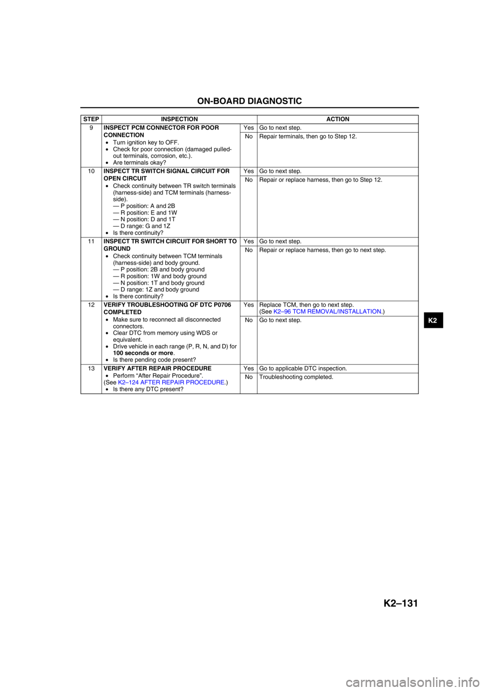
ON-BOARD DIAGNOSTIC
K2–131
K2
End Of Sie
9INSPECT PCM CONNECTOR FOR POOR
CONNECTION
•Turn ignition key to OFF.
•Check for poor connection (damaged pulled-
out terminals, corrosion, etc.).
•Are terminals okay?Yes Go to next step.
No Repair terminals, then go to Step 12.
10INSPECT TR SWITCH SIGNAL CIRCUIT FOR
OPEN CIRCUIT
•Check continuity between TR switch terminals
(harness-side) and TCM terminals (harness-
side).
—P position: A and 2B
—R position: E and 1W
—N position: D and 1T
—D range: G and 1Z
•Is there continuity?Yes Go to next step.
No Repair or replace harness, then go to Step 12.
11INSPECT TR SWITCH CIRCUIT FOR SHORT TO
GROUND
•Check continuity between TCM terminals
(harness-side) and body ground.
—P position: 2B and body ground
—R position: 1W and body ground
—N position: 1T and body ground
—D range: 1Z and body ground
•Is there continuity?Yes Go to next step.
No Repair or replace harness, then go to next step.
12VERIFY TROUBLESHOOTING OF DTC P0706
COMPLETED
•Make sure to reconnect all disconnected
connectors.
•Clear DTC from memory using WDS or
equivalent.
•Drive vehicle in each range (P, R, N, and D) for
100 seconds or more.
•Is there pending code present?Yes Replace TCM, then go to next step.
(See K2–96 TCM REMOVAL/INSTALLATION.)
No Go to next step.
13VERIFY AFTER REPAIR PROCEDURE
•Perform “After Repair Procedure”.
(See K2–124 AFTER REPAIR PROCEDURE.)
•Is there any DTC present?Yes Go to applicable DTC inspection.
No Troubleshooting completed. STEP INSPECTION ACTION
Page 759 of 909

P–26
ON-BOARD DIAGNOSTIC
DTC C1119A6E697067650202
DTC C1119 Engine control system, torque reduction inhibit signal line
DETECTION
CONDITION•Engine RPM information through CAN is out of specification
•Throttle information through CAN is out of specification
•Fuel injection information through CAN is invalid or out of specification (for MZR-CD (RF Turbo) only).
•Received control inhibition signal from PCM through CAN.
POSSIBLE
CAUSE•Malfunction of PCM
•Malfunction of CAN
PCM
PCM HARNESS SIDE CONNECTOR (L3, L8, LF)
2U2R
CAN LINEABS (ABS/TCS): O
DSC: AG
ABS (ABS/TCS): R
DSC: AF
AQ
B
CDE
FG
HI
J DSC HU/CU HARNESS SIDE CONNECTOR
A
C E
H
K N Q
T
W Z AC AF
F I L O R U X
AA AD AG
G
J
M P S
V
Y AB
AE AHB
DKN
T
WZ
AC
AFLO
RU
XAA
ADAGMP
SV
YAB
AEAH
SST (49 G066 001) CONNECTOR
AD AC AB AAA Q
B R
C S
D T
E U
F V
G W
H X
I Y
J L M
O PZ ABS (ABS/TCS) HU/CM HARNESS SIDE CONNECTOR
ADAC
ABAA
A
B
C D
E
F G
H
I J
L M
O P
Q
R S
T
U V
W
X Y
Z
SST (49 G066 004) CONNECTOR
PCM HARNESS SIDE CONNECTOR (MZR-CD (RF TURBO))
13
39
L8, LF, L3: 2U
MZR-CD
(RF TURBO): 13
L8, LF, L3: 2R
MZR-CD
(RF TURBO): 39