2002 MAZDA 6 oil
[x] Cancel search: oilPage 495 of 909

K2–80
AUTOMATIC TRANSAXLE
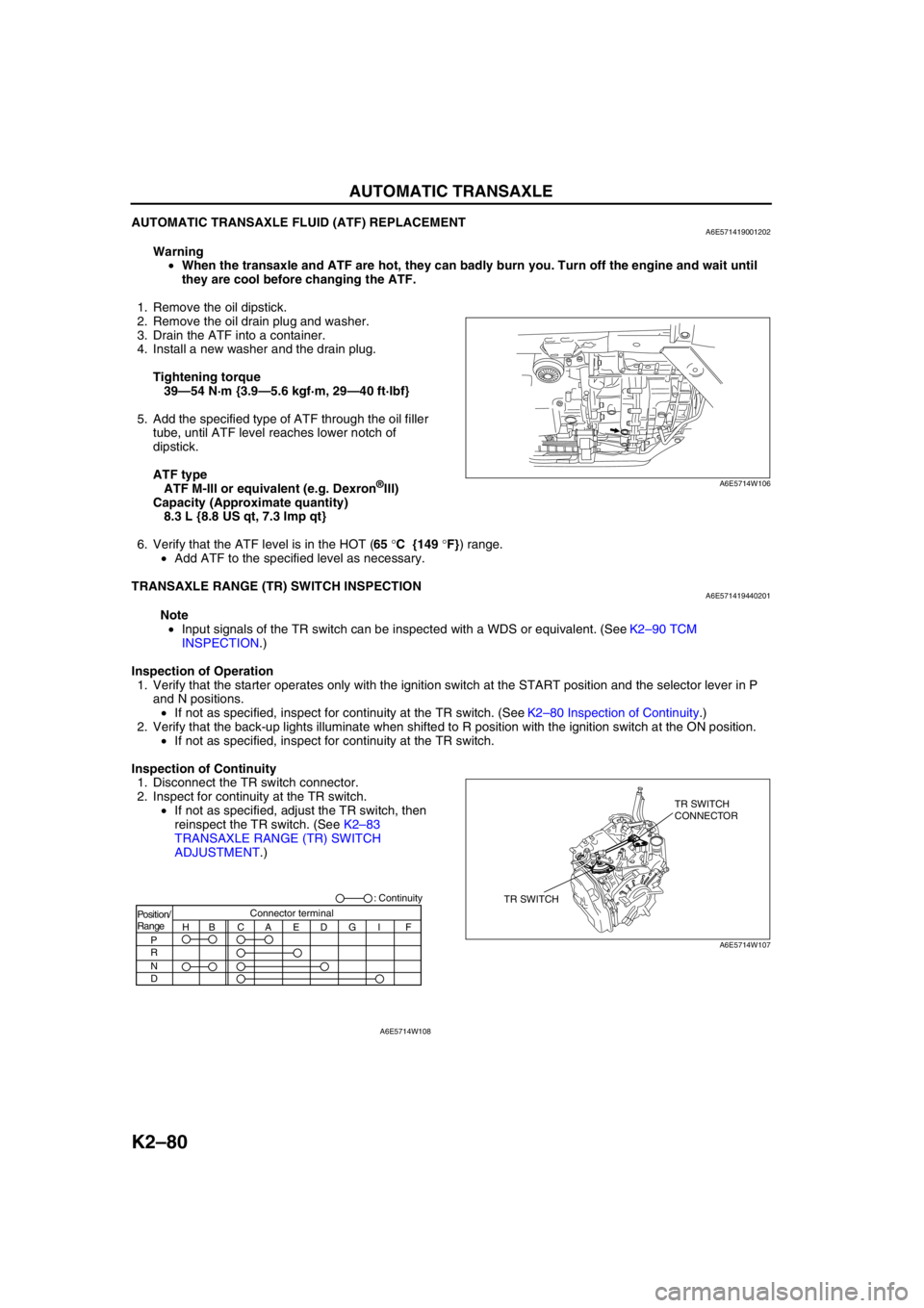
AUTOMATIC TRANSAXLE FLUID (ATF) REPLACEMENTA6E571419001202
Warning
•When the transaxle and ATF are hot, they can badly burn you. Turn off the engine and wait until
they are cool before changing the ATF.
1. Remove the oil dipstick.
2. Remove the oil drain plug and washer.
3. Drain the ATF into a container.
4. Install a new washer and the drain plug.
Tightening torque
39—54 N·m {3.9—5.6 kgf·m, 29—40 ft·lbf}
5. Add the specified type of ATF through the oil filler
tube, until ATF level reaches lower notch of
dipstick.
ATF type
ATF M-III or equivalent (e.g. Dexron
®III)
Capacity (Approximate quantity)
8.3 L {8.8 US qt, 7.3 Imp qt}
6. Verify that the ATF level is in the HOT (65 °C {149 °F}) range.
•Add ATF to the specified level as necessary.
End Of Sie
TRANSAXLE RANGE (TR) SWITCH INSPECTIONA6E571419440201
Note
•Input signals of the TR switch can be inspected with a WDS or equivalent. (See K2–90 TCM
INSPECTION.)
Inspection of Operation
1. Verify that the starter operates only with the ignition switch at the START position and the selector lever in P
and N positions.
•If not as specified, inspect for continuity at the TR switch. (See K2–80 Inspection of Continuity.)
2. Verify that the back-up lights illuminate when shifted to R position with the ignition switch at the ON position.
•If not as specified, inspect for continuity at the TR switch.
Inspection of Continuity
1. Disconnect the TR switch connector.
2. Inspect for continuity at the TR switch.
•If not as specified, adjust the TR switch, then
reinspect the TR switch. (See K2–83
TRANSAXLE RANGE (TR) SWITCH
ADJUSTMENT.)
A6E5714W106
TR SWITCHTR SWITCH
CONNECTOR
A6E5714W107
Position/
Range
H
P
R
N
DBCAEDGI FConnector terminal: Continuity
A6E5714W108
Page 499 of 909

K2–84
AUTOMATIC TRANSAXLE
TRANSAXLE FLUID TEMPERATURE (TFT) SENSOR INSPECTIONA6E5714190102021. Disconnect the terminal component No.2
connector.
2. Remove the oil dipstick.
3. Insert the thermistor probe into the filler tube.
4. Start the engine.
5. Measure resistance between the terminals G and
H.
•If not as specified, replace the TFT sensor.
(See K2–99 AUTOMATIC TRANSAXLE AND
TRANSFER REMOVAL/INSTALLATION.)
(See Automatic Transaxle Workshop Manual
JA5A-EL.)
6. Connect the terminal component No.2 connector.
End Of Sie
ATF temperature (°C {°F}) Resistance (kilohm)
-20 {-4} 15.87—17.54
0 {32} 5.73—6.33
20 {68} 2.38—2.63
40 {104} 1.10—1.22
60 {140} 0.56—0.62
80 {176} 0.31—0.34
100 {212} 0.18—0.20
120 {248} 0.11—0.12
130 {266} 0.09—0.10
TERMINAL COMPONENT No.2
A6E5714W117
A6E5614W003
ACEG
BDFH
A6E5714W118
INCREASES
RESISTANCE (ohm)
ATF TEMPERATURE INCREASESCHARACTERISTIC
OF TFT SENSOR
A6E5714W119
Page 514 of 909

AUTOMATIC TRANSAXLE
K2–99
K2
AUTOMATIC TRANSAXLE AND TRANSFER REMOVAL/INSTALLATIONA6E5714190902011. Disconnect the negative battery cable.
2. Remove the battery and battery tray.
3. Remove the aircleaner component. (See Sectin F.)
4. Remove the front tires and splash shield.
5. Remove the under cover.
6. Separate the steering shaft and steering hose. (See N–13 STEERING GEAR AND LINKAGE (4WD)
REMOVAL/INSTALLATION.)
7. Remove the front auto leveling sensor. (See Section T.)
8. Drain the ATF. (See K2–80 AUTOMATIC TRANSAXLE FLUID (ATF) REPLACEMENT.)
Warning
•Improperly jacking a transaxle is dangerous. It can slip off the jack and may cause serious injury.
Caution
•To prevent the torque converter and transaxle from separating, remove the transaxle without
tilting it toward the torque converter.
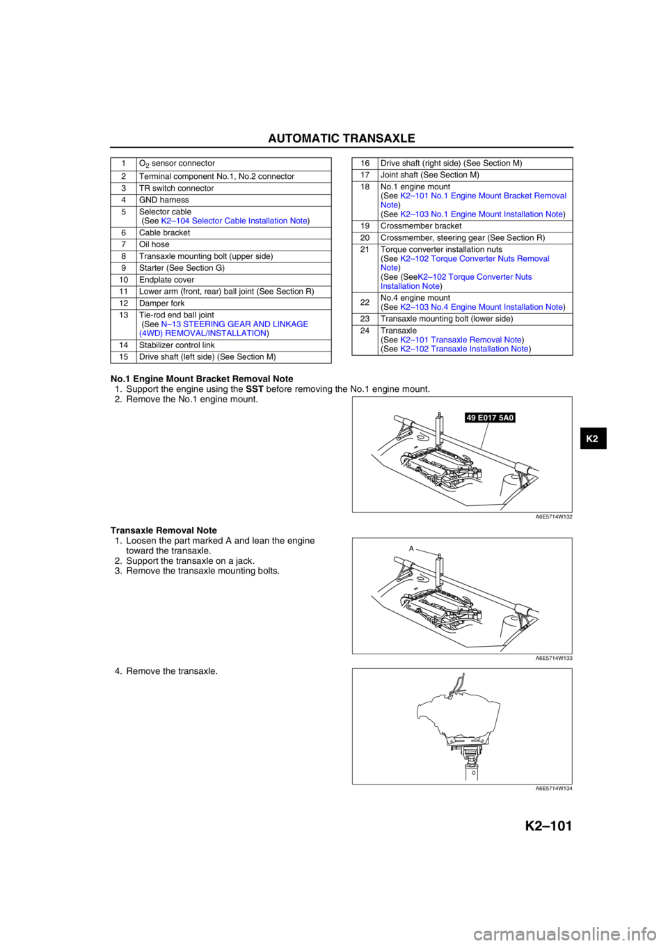
9. Remove in the order shown in the figure.
10. Install in the reverse order of removal.
11. Adjust the headlight zeroset. (See Section T.)
12. Add ATF to the specified level. (See K2–80 AUTOMATIC TRANSAXLE FLUID (ATF) REPLACEMENT.)
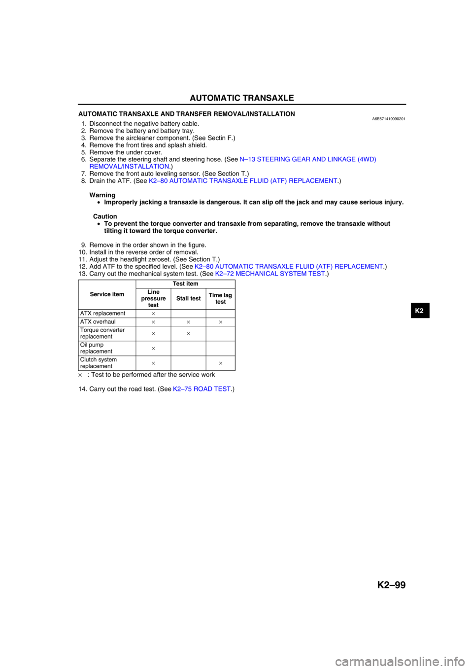
13. Carry out the mechanical system test. (See K2–72 MECHANICAL SYSTEM TEST.)
×: Test to be performed after the service work
14. Carry out the road test. (See K2–75 ROAD TEST.)
Service itemTest item
Line
pressure
testStall testTime lag
test
ATX replacement×
ATX overhaul×××
Torque converter
replacement××
Oil pump
replacement×
Clutch system
replacement××
Page 516 of 909

AUTOMATIC TRANSAXLE
K2–101
K2
No.1 Engine Mount Bracket Removal Note
1. Support the engine using the SST before removing the No.1 engine mount.
2. Remove the No.1 engine mount.
Transaxle Removal Note
1. Loosen the part marked A and lean the engine
toward the transaxle.
2. Support the transaxle on a jack.
3. Remove the transaxle mounting bolts.
4. Remove the transaxle.
1O2 sensor connector
2 Terminal component No.1, No.2 connector
3 TR switch connector
4 GND harness
5 Selector cable
(See K2–104 Selector Cable Installation Note)
6 Cable bracket
7 Oil hose
8 Transaxle mounting bolt (upper side)
9 Starter (See Section G)
10 Endplate cover
11 Lower arm (front, rear) ball joint (See Section R)
12 Damper fork
13 Tie-rod end ball joint
(See N–13 STEERING GEAR AND LINKAGE
(4WD) REMOVAL/INSTALLATION)
14 Stabilizer control link
15 Drive shaft (left side) (See Section M)16 Drive shaft (right side) (See Section M)
17 Joint shaft (See Section M)
18 No.1 engine mount
(See K2–101 No.1 Engine Mount Bracket Removal
Note)
(See K2–103 No.1 Engine Mount Installation Note)
19 Crossmember bracket
20 Crossmember, steering gear (See Section R)
21 Torque converter installation nuts
(See K2–102 Torque Converter Nuts Removal
Note)
(See (SeeK2–102 Torque Converter Nuts
Installation Note)
22No.4 engine mount
(See K2–103 No.4 Engine Mount Installation Note)
23 Transaxle mounting bolt (lower side)
24 Transaxle
(See K2–101 Transaxle Removal Note)
(See K2–102 Transaxle Installation Note)
49 E017 5A0
A6E5714W132
A
A6E5714W133
A6E5714W134
Page 519 of 909

K2–104
AUTOMATIC TRANSAXLE
4. Tighten the bolt A.
Tightening torque
A: 93.1—116.6 N·m
{9.50—11.88 kgf·m, 68.66—85.98 ft·lbf}
B: 85.3—116.6 N·m
{8.70—11.88 kgf·m, 62.91—85.98 ft·lbf}
Selector Cable Installation Note
1. Install the selector lever to the manual shaft lever
in such a way that the selector cable does not
bear a load.
Note
•Install the selector lever to the manual shaft
lever with the spring side of the selector
cable end facing the upward of the vehicle.
2. Confirm that the end of the manual shaft lever
sticks out of the end of the selector cable.
End Of SieOIL SEAL REMOVAL/INSTALLATIONA6E571419240201Differential side
1. Drain the ATF. (See K2–80 AUTOMATIC TRANSAXLE FLUID (ATF) REPLACEMENT.)
2. Remove the drive shaft. (See Section M.)
3. Remove and discard the oil seal using a screwdriver.
4. Using the SSTs and a hammer, tap a new oil seal
in evenly until the SSTs contacts the transaxle
case.
5. Coat the lip of the oil seal with ATF.
Caution
•The oil seal is easily damaged by the
sharp edges of the drive shaft splines. Do
not let the splines contact the oil seal.
6. Install the drive shaft. (See Section M.)
7. Add ATF to the specified level. (See K2–80
AUTOMATIC TRANSAXLE FLUID (ATF)
REPLACEMENT.)
8. Carry out the mechanical system test. (See K2–72 MECHANICAL SYSTEM TEST.)
Transfer side
1. Remove the drive shaft and joint shaft. (See Section M.)
2. Remove and discard the oil seal using a screwdriver.
3. Using the SST and a hammer, tap a new oil seal
in evenly until the SST contacts the transfer case.
AC
B
D
A6E5714W138
SELECTOR CABLE
MANUAL SHAFT LEVERSPRING
UPWARD
A6E5714W115
49 G030 79749 L019 016
-1.1—-0.1 mm
{-0.043—-0.004 in}
A6E5714W142
49 B010 001
A6E5714W129
Page 520 of 909

AUTOMATIC TRANSAXLE
K2–105
K2
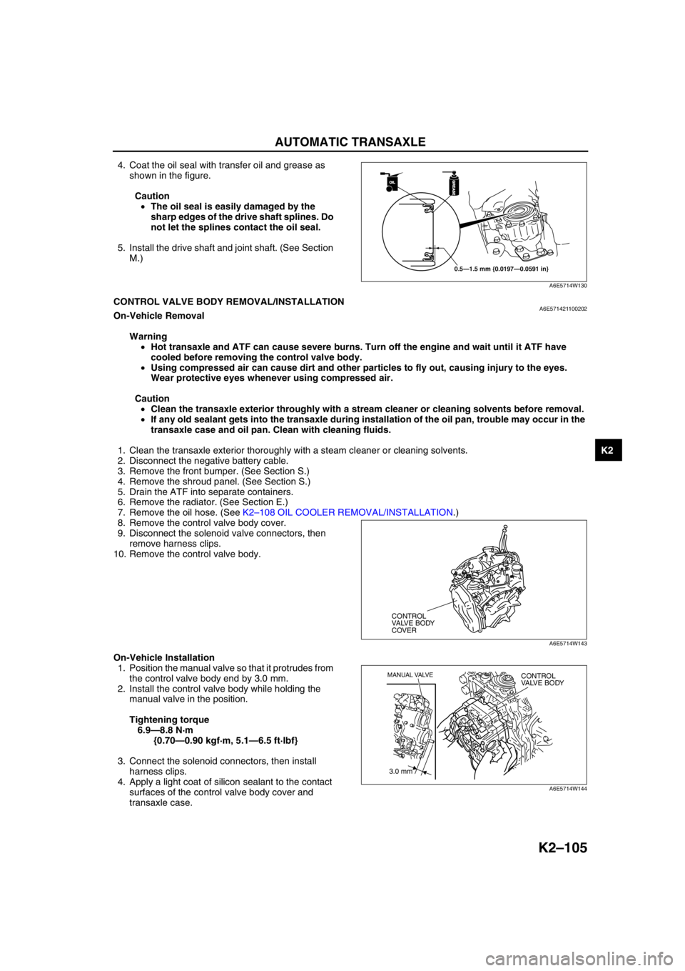
4. Coat the oil seal with transfer oil and grease as
shown in the figure.
Caution
•The oil seal is easily damaged by the
sharp edges of the drive shaft splines. Do
not let the splines contact the oil seal.
5. Install the drive shaft and joint shaft. (See Section
M.)
End Of SieCONTROL VALVE BODY REMOVAL/INSTALLATIONA6E571421100202On-Vehicle Removal
Warning
•Hot transaxle and ATF can cause severe burns. Turn off the engine and wait until it ATF have
cooled before removing the control valve body.
•Using compressed air can cause dirt and other particles to fly out, causing injury to the eyes.
Wear protective eyes whenever using compressed air.
Caution
•Clean the transaxle exterior throughly with a stream cleaner or cleaning solvents before removal.
•If any old sealant gets into the transaxle during installation of the oil pan, trouble may occur in the
transaxle case and oil pan. Clean with cleaning fluids.
1. Clean the transaxle exterior thoroughly with a steam cleaner or cleaning solvents.
2. Disconnect the negative battery cable.
3. Remove the front bumper. (See Section S.)
4. Remove the shroud panel. (See Section S.)
5. Drain the ATF into separate containers.
6. Remove the radiator. (See Section E.)
7. Remove the oil hose. (See K2–108 OIL COOLER REMOVAL/INSTALLATION.)
8. Remove the control valve body cover.
9. Disconnect the solenoid valve connectors, then
remove harness clips.
10. Remove the control valve body.
On-Vehicle Installation
1. Position the manual valve so that it protrudes from
the control valve body end by 3.0 mm.
2. Install the control valve body while holding the
manual valve in the position.
Tightening torque
6.9—8.8 N·m
{0.70—0.90 kgf·m, 5.1—6.5 ft·lbf}
3. Connect the solenoid connectors, then install
harness clips.
4. Apply a light coat of silicon sealant to the contact
surfaces of the control valve body cover and
transaxle case.
OILOIL
0.5—1.5 mm {0.0197—0.0591 in}
GREASEGREASE
A6E5714W130
CONTROL
VALVE BODY
COVER
A6E5714W143
3.0 mm
MANUAL VALVECONTROL
VALVE BODY
A6E5714W144
Page 521 of 909

K2–106
AUTOMATIC TRANSAXLE
5. Install the control valve body cover.
Tightening torque
6.9—8.8 N·m
{0.70—0.90 kgf·m, 5.1—6.5 ft·lbf}
6. Install the oil hose and oil pipe. (See K2–108 OIL
COOLER REMOVAL/INSTALLATION.)
7. Install the radiator. (See Section E.)
8. Install the shroud panel. (See Section S.)
9. Install the front bumper. (See Section S.)
10. Connect the negative battery cable.
11. Fill the transaxle with the specified ATF. (See K2–
80 AUTOMATIC TRANSAXLE FLUID (ATF)
REPLACEMENT.)
12. Inspect for leakage of ATF from the oil pan or the oil hose connecting points.
13. Carry out the mechanical system test. (See K2–72 MECHANICAL SYSTEM TEST.)
14. Carry out the road test. (See K2–75 ROAD TEST.)
End Of Sie
OIL COOLER FLUSHINGA6E571419900202
Caution
•Power flushing should be performed very carefully when removing the accumulated debris from
the fluid baffle, otherwise the debris cannot be removed or the problem becomes even worse.
Note
•The contaminated cooler line (oil pipes and hoses) and auxiliary cooler (if equipped) must be flushed
completely when ATX is overhauled or replaced.
•Performing back and reverse power flushing two times each does not work because debris or particles
flow out from the feed pipe side of ATX.
Recommended power-flushing manufacturer
Power Flushing
Repair procedure
1. Before power flushing, inspect the hoses/lines and clamps. Power flushing must begin with back flushing
followed by forward flushing to quickly dislodge the restriction. If back flushing is not performed before forward
flushing, the restriction could further reduce the ATF flow through the internal mesh type baffle of the cooler and
flushing will not be effective or possible.
Inspecting oil lines & clamps
1. Be sure to inspect the lines (hoses/pipes) for cuts, crimps (pinched), cracks or any other damage before
reusing them. If any problem exists replace it.
Caution
•Always use new clamps when replacing hoses.
CONTROL
VALVE BODY
COVER
A6E5714W143
Manufacturer Part number Description
Kent Moore J35944-AMAZFlushing kit or
equivalent
OTC 60081Portable torque
converter, oil cooler
cleaner or equivalent
Page 522 of 909

AUTOMATIC TRANSAXLE
K2–107
K2
Back flushing
1. Using the power flushing equipment
manufacturer's instructions, connect equipment
so the flushing fluid flows in the opposite direction
of normal fluid flow.
2. Flush oil cooler/lines until discharge fluid is clean.
Caution
•If the cooler can not be properly flushed
using recommended equipment, send the
radiator out for sublet cleaning or
replace.
Forward flushing
1. Connect power flushing equipment so the flushing
fluid flows in the direction of normal fluid flow.
2. Flush oil cooler/lines until discharge fluid is clean.
End Of Sie
FLUSHING FLUID OUT FLUSHING FLUID IN
A6E5714W145
FLUSHING FLUID IN FLUSHING FLUID OUT
A6E5714W147