2002 LAND ROVER DISCOVERY tow
[x] Cancel search: towPage 1230 of 1672
SUNROOF
REPAIRS 76-6-15
Glass panel - sunroof
$% 76.84.03
The procedure for replacing the rear sunroof glass
panel is exactly the same as for the front
Remove
1.Partially open sunroof.
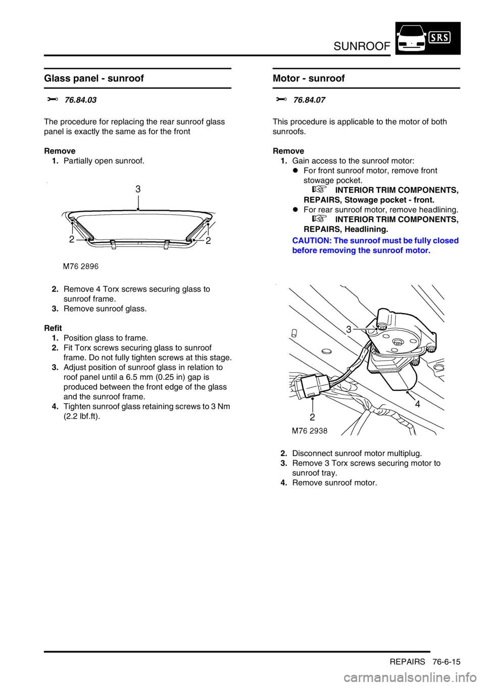
2.Remove 4 Torx screws securing glass to
sunroof frame.
3.Remove sunroof glass.
Refit
1.Position glass to frame.
2.Fit Torx screws securing glass to sunroof
frame. Do not fully tighten screws at this stage.
3.Adjust position of sunroof glass in relation to
roof panel until a 6.5 mm (0.25 in) gap is
produced between the front edge of the glass
and the sunroof frame.
4.Tighten sunroof glass retaining screws to 3 Nm
(2.2 lbf.ft).
Motor - sunroof
$% 76.84.07
This procedure is applicable to the motor of both
sunroofs.
Remove
1.Gain access to the sunroof motor:
lFor front sunroof motor, remove front
stowage pocket.
+ INTERIOR TRIM COMPONENTS,
REPAIRS, Stowage pocket - front.
lFor rear sunroof motor, remove headlining.
+ INTERIOR TRIM COMPONENTS,
REPAIRS, Headlining.
CAUTION: The sunroof must be fully closed
before removing the sunroof motor.
2.Disconnect sunroof motor multiplug.
3.Remove 3 Torx screws securing motor to
sunroof tray.
4.Remove sunroof motor.
Page 1231 of 1672
SUNROOF
76-6-16 REPAIRS
Refit
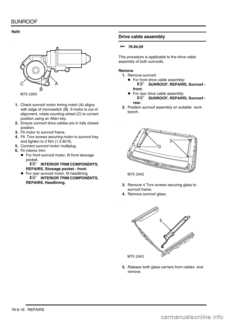
1.Check sunroof motor timing notch (A) aligns
with edge of microswitch (B). If motor is out of
alignment, rotate counting wheel (C) to correct
position using an Allen key.
2.Ensure sunroof drive cables are in fully closed
position.
3.Fit motor to sunroof frame.
4.Fit Torx screws securing motor to sunroof tray
and tighten to 2 Nm (1.5 lbf.ft).
5.Connect sunroof motor multiplug.
6.Fit interior trim:
lFor front sunroof motor, fit front stowage
pocket.
+ INTERIOR TRIM COMPONENTS,
REPAIRS, Stowage pocket - front.
lFor rear sunroof motor, fit headlining.
+ INTERIOR TRIM COMPONENTS,
REPAIRS, Headlining.
Drive cable assembly
$% 76.84.09
This procedure is applicable to the drive cable
assembly of both sunroofs.
Remove
1.Remove sunroof:
lFor front drive cable assembly:
+ SUNROOF, REPAIRS, Sunroof -
front.
lFor rear drive cable assembly:
+ SUNROOF, REPAIRS, Sunroof -
rear.
2.Position sunroof assembly on suitable work
bench.
3.Remove 4 Torx screws securing glass to
sunroof frame.
4.Remove sunroof glass.
5.Release both glass carriers from cables and
remove.
Page 1232 of 1672
SUNROOF
REPAIRS 76-6-17
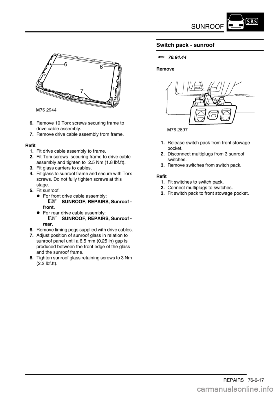
6.Remove 10 Torx screws securing frame to
drive cable assembly.
7.Remove drive cable assembly from frame.
Refit
1.Fit drive cable assembly to frame.
2.Fit Torx screws securing frame to drive cable
assembly and tighten to 2.5 Nm (1.8 lbf.ft).
3.Fit glass carriers to cables.
4.Fit glass to sunroof frame and secure with Torx
screws. Do not fully tighten screws at this
stage.
5.Fit sunroof.
lFor front drive cable assembly:
+ SUNROOF, REPAIRS, Sunroof -
front.
lFor rear drive cable assembly:
+ SUNROOF, REPAIRS, Sunroof -
rear.
6.Remove timing pegs supplied with drive cables.
7.Adjust position of sunroof glass in relation to
sunroof panel until a 6.5 mm (0.25 in) gap is
produced between the front edge of the glass
and the sunroof frame.
8.Tighten sunroof glass retaining screws to 3 Nm
(2.2 lbf.ft).
Switch pack - sunroof
$% 76.84.44
Remove
1.Release switch pack from front stowage
pocket.
2.Disconnect multiplugs from 3 sunroof
switches.
3.Remove switches from switch pack.
Refit
1.Fit switches to switch pack.
2.Connect multiplugs to switches.
3.Fit switch pack to front stowage pocket.
Page 1233 of 1672
SUNROOF
76-6-18 REPAIRS
ECU - sunroof
$% 76.84.46
Remove
1.Remove front stowage pocket.
+ INTERIOR TRIM COMPONENTS,
REPAIRS, Stowage pocket - front.
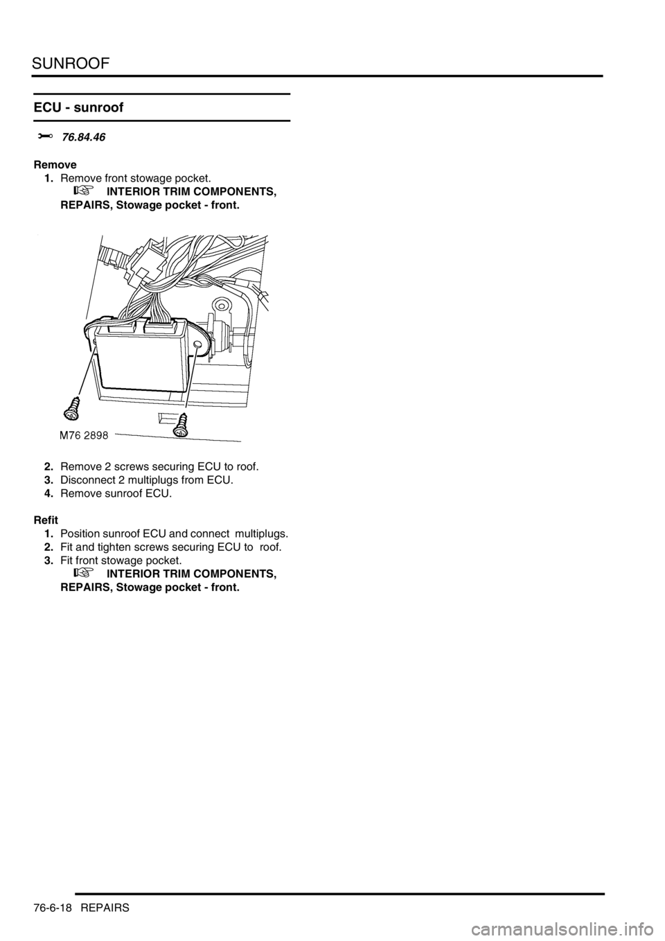
2.Remove 2 screws securing ECU to roof.
3.Disconnect 2 multiplugs from ECU.
4.Remove sunroof ECU.
Refit
1.Position sunroof ECU and connect multiplugs.
2.Fit and tighten screws securing ECU to roof.
3.Fit front stowage pocket.
+ INTERIOR TRIM COMPONENTS,
REPAIRS, Stowage pocket - front.
Page 1321 of 1672
CORROSION PREVENTION AND SEALING
77-4-6 CORROSION PREVENTION
Corrosion prevention
Factory treatments
During production, vehicle bodies are treated with the following anti-corrosion materials:
lA PVC-based underbody sealer which is sprayed onto the underside of the main floor, rear floor, front and rear
wheelarches and the front valance assembly;
lAn application of cavity wax which is sprayed into the sill panels, 'A' post, 'B-C' post, fuel filler aperture, body rear
panel and the lower areas of the door panels;
lA coating of underbody wax which is applied to the entire underbody inboard of the sill vertical flanges, and
covers all moving and flexible components EXCEPT for wheels, tyres, brakes and exhaust;
lA coat of protective wax applied to the engine bay area.
Whenever body repairs are carried out, ensure the anti-corrosion materials in the affected area are repaired or
renewed as necessary using the approved materials.
+ BODY SEALING MATERIALS, MATERIALS AND APPLICATIONS, Approved materials.
Precautions during body repairs and handling
Take care when handling the vehicle in the workshop. Underbody sealers, seam sealers, underbody wax and body
panels may be damaged if the vehicle is carelessly lifted.
+ LIFTING AND TOWING, LIFTING.
Proprietary anti-corrosion treatments
The application of proprietary anti-corrosion treatments, in addition to the factory-applied treatment, could invalidate
the Corrosion Warranty and should be discouraged. This does not apply to Rover approved, compatible, preservative
waxes which may be applied on top of existing coatings.
Fitting approved accessories
When fitting accessories ensure that the vehicle's corrosion protection is not affected, either by breaking the protective
coating or by introducing a moisture trap.
Do not screw self-tapping screws directly into body panels. Fit suitable plastic inserts to the panel beforehand. Always
ensure that the edges of holes drilled into panels, chassis members and other body parts are protected with a suitable
zinc rich or acid etch primer, and follow with a protective wax coating brushed onto the surrounding area.
Do not attach painted metal surfaces of any accessory directly to the vehicle's bodywork unless suitably protected.
Where metal faces are bolted together always interpose a suitable interface material such as weldable zinc rich
primer, extruded strip, or zinc tape.
Steam cleaning and dewaxing
Due to the high temperatures generated by steam cleaning equipment, there is a risk that certain trim components
could be damaged and some adhesives and corrosion prevention materials softened or liquified.
Adjust the equipment so that the nozzle temperature does not exceed 90
° C (194° F). Take care not to allow the steam
jet to dwell on one area, and keep the nozzle at least 300 mm (11.811 in) from panel surfaces.
DO NOT remove wax or lacquer from underbody or underbonnet areas during repairs. Should it be necessary to
steam clean these areas, apply a new coating of wax or underbody protection as soon as possible.
Inspections during maintenance servicing
It is a requirement of the Corrosion Warranty that the vehicle body is checked for corrosion by an authorised Land
Rover Dealer at least once a year, to ensure that the factory-applied protection remains effective.
Service Job Sheets include the following operations to check bodywork for corrosion:
lWith the vehicle on a lift, carry out visual check of underbody sealer for damage;
lWith the vehicle lowered, inspect exterior paintwork for damage and body panels for corrosion.
It will be necessary for the vehicle to be washed by the Dealer prior to inspection of bodywork if the customer has
offered the vehicle in a dirty condition.
Page 1350 of 1672
HEATING AND VENTILATION
DESCRIPTION AND OPERATION 80-9
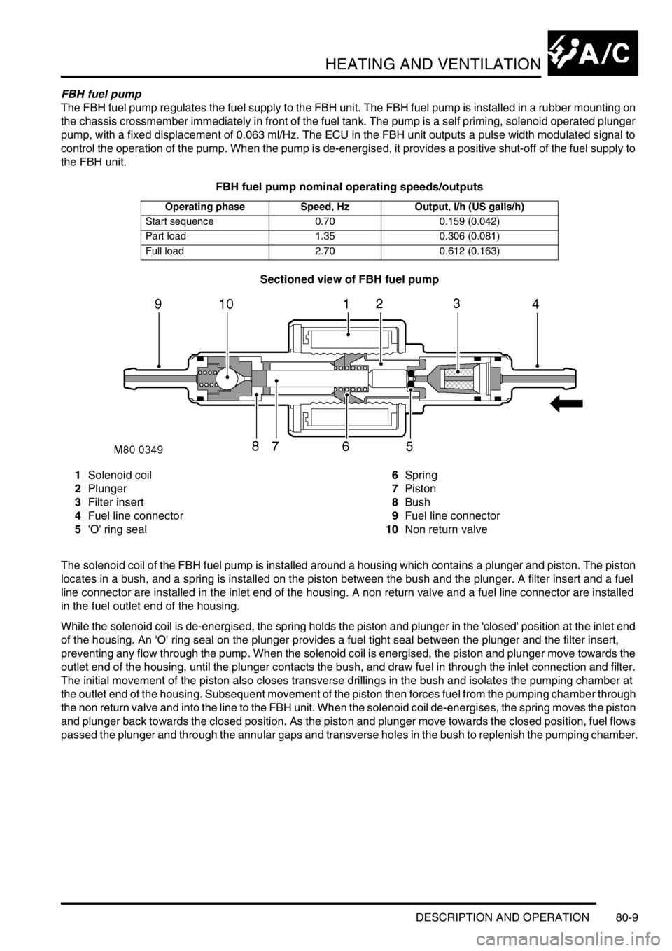
FBH fuel pump
The FBH fuel pump regulates the fuel supply to the FBH unit. The FBH fuel pump is installed in a rubber mounting on
the chassis crossmember immediately in front of the fuel tank. The pump is a self priming, solenoid operated plunger
pump, with a fixed displacement of 0.063 ml/Hz. The ECU in the FBH unit outputs a pulse width modulated signal to
control the operation of the pump. When the pump is de-energised, it provides a positive shut-off of the fuel supply to
the FBH unit.
FBH fuel pump nominal operating speeds/outputs
Sectioned view of FBH fuel pump
1Solenoid coil
2Plunger
3Filter insert
4Fuel line connector
5'O' ring seal6Spring
7Piston
8Bush
9Fuel line connector
10Non return valve
The solenoid coil of the FBH fuel pump is installed around a housing which contains a plunger and piston. The piston
locates in a bush, and a spring is installed on the piston between the bush and the plunger. A filter insert and a fuel
line connector are installed in the inlet end of the housing. A non return valve and a fuel line connector are installed
in the fuel outlet end of the housing.
While the solenoid coil is de-energised, the spring holds the piston and plunger in the 'closed' position at the inlet end
of the housing. An 'O' ring seal on the plunger provides a fuel tight seal between the plunger and the filter insert,
preventing any flow through the pump. When the solenoid coil is energised, the piston and plunger move towards the
outlet end of the housing, until the plunger contacts the bush, and draw fuel in through the inlet connection and filter.
The initial movement of the piston also closes transverse drillings in the bush and isolates the pumping chamber at
the outlet end of the housing. Subsequent movement of the piston then forces fuel from the pumping chamber through
the non return valve and into the line to the FBH unit. When the solenoid coil de-energises, the spring moves the piston
and plunger back towards the closed position. As the piston and plunger move towards the closed position, fuel flows
passed the plunger and through the annular gaps and transverse holes in the bush to replenish the pumping chamber.
Operating phase Speed, Hz Output, l/h (US galls/h)
Start sequence 0.70 0.159 (0.042)
Part load 1.35 0.306 (0.081)
Full load 2.70 0.612 (0.163)
Page 1484 of 1672

BODY CONTROL UNIT
DESCRIPTION AND OPERATION 86-3-15
The BCU controls the wiper motor frequency of operation via the IDM when intermittent wipe or wash is selected. The
front intermittent wipe option features five different intermittent delay periods. The shortest delay period is 3 seconds
and this is increased by 2 second increments up to a maximum delay of 11 seconds. The desired delay period for the
front wipers is set by the position of the rotary switch located on the wiper column stalk.
The rear wiper switch is located on the instrument pack cowl and is latched when pressed. The rear wiper electric
motor is located in the tail door. The rear wiper operation is controlled according to a programmed strategy via the
BCU and the IDM. The BCU also checks for a signal from either the reverse lamp switch located in the vehicle gearbox
(manual gearbox models) or the gear position switch (automatic gearbox models) for operating the rear wipers when
the vehicle is in reverse. The rear wiper and washer only operate when the ignition switch is in position II.
The front and rear washer pumps and the headlamp powerwash (where fitted) are also controlled through the BCU.
The washers are operated from electric pumps attached to the washer reservoir located in the left hand wheel arch.
The front wash switch is located on the wiper column stalk and is pulled towards the steering wheel to select the
washer function. When the front washers are operated, the wipers are also activated for three full cycles. The rear
wash switch is located on the instrument pack cowl. The BCU programme can be configured in one of two modes of
operation:
lNo wiper operation when the wash switch is pressed.
lWiper action after an initial delay of 400 ms.
Headlamp wash is activated by the BCU via the IDM and operates when the headlamps are on and the front washers
function is selected.
Electric seats
The BCU controls the logical operation of the electrically operated front seats. Two modes of operation are available:
+ SEATS, DESCRIPTION AND OPERATION, Description - electric seats.
lElectric seat adjustment is enabled if the ignition is on or the driver's door is opened for a short time period.
lElectric seat adjustment is enabled if the ignition is on and the driver's door is closed.
The seats are operated by four electric motors which control the seat cushion rear up/ down, the seat cushion front
up/ down, seat cushion forward/ rearward and seat squab recline. The electrically powered lumbar adjustment in each
seat is operated by a single motorised air pump and a solenoid located on the seat squab frame. The air pump inflates
a cushion in the seat squab and the solenoid operates a valve to deflate the cushion. The seat squab and cushion
may also contain heater elements to provide heated seat operation.
The switches for electrically operated seats are located either side of the centre console.
Direction indicators and hazard warning lamps
The direction indicator lamps are operated from a three position direction indicator switch on the left hand, steering
column stalk. The BCU only allows the lamps to work as direction indicators when the ignition switch is in position II.
The BCU also controls the lamps to operate as hazard warning lamps and as a visual warning for the anti-theft system,
in which cases all lamps flash simultaneously irrespective of the ignition switch position.
System control of the direction indicators and hazard warning lamps is provided by the BCU operating with the IDM
and two electronic relays located in the passenger compartment fuse box. The IDM and relays are integral parts of
the passenger compartment fuse box and cannot be serviced individually. The serial data bus is used for
communication of status and operation requests between the BCU, IDM and instrument pack.
The hazard warning lamps are operated from a latching pushbutton switch located on the fascia.
All direction indicator/ hazard warning lamp bulbs are rated at 5 Watts.