2002 LAND ROVER DISCOVERY oil filter
[x] Cancel search: oil filterPage 892 of 1672

STEERING
DESCRIPTION AND OPERATION 57-5
Description
General
The major steering components comprise an impact absorbing telescopic steering column, a Power Assisted Steering
(PAS) box, a PAS pump, and fluid reservoir. Hydraulic fluid from the fluid reservoir is filtered and then supplied
through the suction line to the inlet on the PAS pump. The PAS pump supplies fluid to the steering box through a
pressure line routed above the front cross member. Fluid returns to the reservoir along the same route through a
return line. On LH drive vehicles the pipe route above the front cross member is still used, the length of pipe acting
as an oil cooler.
To minimise driver's injury in the event of an accident the steering system has a number of safety features including
a collapsible steering column. An additional safety feature is an air bag located in the steering wheel.
+ RESTRAINT SYSTEMS, DESCRIPTION AND OPERATION, Description - SRS.
Steering column assembly and intermediate shaft
The steering column central shaft comprises of two shafts, the upper shaft is splined to accept the steering wheel and
located in bearings in the column tube. A universal joint is located on the bottom of the upper shaft, the joint allows
for angular movement between the upper and lower shafts. The lower shaft is made in two parts, the top section of
the lower shaft is located outside of the lower section. The two sections of the lower shaft are connected by two nylon
injection moulded shear pins. The lower shaft goes through a lower bearing attached to the bulkhead, the lower shaft
is connected by a universal joint to the intermediate shaft in the engine compartment.
Steering column
An upper column tube provides for the location of the steering lock and ignition switch and also the steering switch
gear and a rotary coupler. The rotary coupler provides the electrical connection for the steering wheel mounted airbag,
switches and horn. The upper mounting bracket has two slots, a slotted metal bracket is held in each slot by four resin
shear pins.
The column is mounted on four captive studs which are located on a column mounting bracket. The captive studs
pass through the metal brackets, locknuts secure the steering column to the bulkhead. The two lower mountings are
fixed and cannot move when loads are applied to them. The upper mounting is designed to disengage or deform when
a load is applied, allowing the column to collapse in the event of an accident. The steering column must be replaced
as a complete assembly if necessary.
When an axial load is applied to the upper column tube, energy absorption is achieved by the following mechanism:
lthe mounting bracket deforms,
lthe resin shear pins holding the slotted metal brackets shear,
lthe top mounting bracket slides out of the slotted metal brackets.
The slotted metal brackets remain on the captive studs on the bulkhead. If the column mounting moves, injection
moulded shear pins retaining the two sections of the lower column shaft will shear. This allows the two sections of the
lower shaft to 'telescope' together.
In the event of a collision where the steering box itself moves, two universal joints in the column allow the intermediate
shaft to articulate, minimising movement of the column towards the driver. If movement continues energy absorption
is achieved by the following mechanism:
lthe decouple joint in the intermediate shaft will disengage,
lthe lower section of the steering column shaft will move through the lower bearing,
lthe injection moulded shear pins retaining the two sections of the lower column shaft will shear.
This allows the two sections of the lower shaft to 'telescope' together reducing further column intrusion. Protection to
the drivers face and upper torso is provided by an SRS airbag module located in the centre of the steering wheel.
+ RESTRAINT SYSTEMS, DESCRIPTION AND OPERATION, Description - SRS.
Page 915 of 1672

STEERING
57-28 REPAIRS
7. RH drive models:Remove 4 bolts securing oil
filter housing, remove housing and discard 'O'
ring.
CAUTION: Always fit plugs to open
connections to prevent contamination.
8.Remove bolt securing PAS pipe bracket to
steering box, release pipes and discard 'O'
rings.
CAUTION: Always fit plugs to open
connections to prevent contamination.9.Remove securing nut and bolt and release
Panhard rod.
10.Remove nut securing drag link to drop arm.
Using LRT-57-036, break taper joint and
release drag link.
11. RH drive models with ACE: Remove nut
securing anti-roll bar link lower ball joint and
release joint.
Page 916 of 1672

STEERING
REPAIRS 57-29
12. RH drive models with ACE: Position ACE
control arms to access steering box bolts.
13.With assistance remove 4 securing bolts and
remove steering box.
14.Remove centralising bolt from steering box. Refit
1.Fit centralising bolt to steering box.
2. With assistance, position steering box, fit bolts
and tighten to 90 Nm (66 lbf.ft).
3. RH drive models with ACE: Ensure washer is
in place on lower ball joint of anti-roll bar link,
then connect lower ball joint to axle. Tighten nut
to 100 Nm (74 lbf.ft).
4.Position drag link, fit nut and tighten to 80 Nm
(59 lbf.ft).
5.Position Panhard rod, fit bolt and nut and
tighten to 230 Nm (170 lbf.ft).
6.Clean PAS pipe ends and 'O' ring recess.
7.Lubricate new 'O' rings for PAS pipes with clean
PAS fluid.
8.Fit 'O' rings to PAS pipes and position pipes in
steering box. Fit PAS pipe bracket and tighten
bolt to 22 Nm (16 lbf.ft).
9. RHD models: Fit oil filter and housing:
lClean oil filter housing and engine mating
faces.
lLubricate new 'O' ring with clean engine oil
and fit to housing.
lPosition oil filter housing and tighten bolts to
9 Nm (7 lbf.ft).
10.Ensure steering wheel is centralised. Fit
universal joint between steering box and
intermediate shaft and tighten bolts to 25 Nm
(18 lbf.ft).
11.Remove centralising bolt from steering box.
12.Fit road wheel(s) and tighten nuts to 140 Nm
(103 lbf.ft)..
13.Remove stand(s) and lower vehicle.
14.Check and top up engine oil.
15.Bleed PAS system.
+ STEERING, ADJUSTMENTS,
Hydraulic system - bleed.
16.Centralise steering linkage
+ STEERING, ADJUSTMENTS,
Steering linkage - centralise.
Page 955 of 1672

FRONT SUSPENSION
60-16 DESCRIPTION AND OPERATION
Valve block
1Cap
2'O' ring
3Coil
4'O' ring
5Directional control valve 1 (extend)
6Pressure transducer
7Mounting bush 3 off
8Valve block
9'O' ring
10High pressure filter
11'O' ring
12Cap13Stud 4 off
14Pipe connections
15Cap
16'O' ring
17Coil
18'O' ring
19Pressure control valve
20Directional control valve 2 (retract)
21'O' ring
22Coil
23'O' ring
24Cap
Page 956 of 1672

FRONT SUSPENSION
DESCRIPTION AND OPERATION 60-17
The valve block directs hydraulic pressure to the actuators via solenoid operated directional control valves. A solenoid
operated pressure control valve regulates the required pressure to the actuators. The three valve solenoids are
controlled by signals received from the ACE ECU. A pressure transducer monitors the pressure delivered by the
pump. A replacable high pressure filter is installed into the lower face of the valve block and filters fluid before it
reaches the valves.
The valve block is located on the outside of the right hand chassis longitudinal. The valve block is secured to the
chassis with three bolts and rubber bushes. The rubber bushes isolate the valve block from the chassis, preventing
hydraulic noise from the valve block transmitting through the chassis and body.
The two solenoid operated directional control valves (DCV's) are fitted to ports in the top face of the valve block. The
DCV's are screwed into the valve block and sealed with O ring seals. Each DCV has a solenoid for electrical operation
of the valve. The solenoid is sealed to the DCV with two O ring and secured with a cap. The cap, coil and O rings are
serviceable items. The DCV's are non-serviceable and failure of a DCV requires the replacement of the valve block
assembly.
The pressure control valve is fitted to a port in the rear face of the valve block. The pressure control valve is screwed
into the valve block and sealed with O rings. The pressure control valve has a coil for electrical operation. The coil is
sealed to the pressure control valve with two O rings and secured with a cap. The cap, coil and O rings are serviceable
items. The pressure control valve is non-serviceable and failure requires replacement of the valve block assembly.
The pressure transducer is fitted to a port in the forward face of the valve block. The pressure transducer is screwed
into the valve block and sealed with an O ring seal. The pressure transducer is a serviceable item.
The high pressure filter locates in a port on the lower face of the valve block. The gauze and fibre filter is sealed in
the port with O ring seals. A threaded cap secures the filter in the valve block and is also sealed with an O ring seal.
A threaded hole on the lower face of the filter allows a bolt to be fitted to remove the filter from the port. If a system
component is replaced, the filter must be changed.
Four ports are located on the forward face of the valve block and two ports on the rear. Each port is fitted with a seal
pack which contains two O ring seals and backing rings. The ACE pipes locate and seal in the seal packs and are
secured to the valve block with the studs and nuts located on the forward and rear faces.
Actuators
Two actuators are used for the ACE system and are attached to the front and rear torsion bars. The actuators apply
hydraulically generated force to the torsion bar to oppose lateral forces caused by the vehicle cornering.
Each actuator is a conventional double-acting cylinder. A piston is attached to a rod and moves within the cylinder
when hydraulic pressure is applied. The rod is sealed at the point where it exits the cylinder. The outer end of the rod
is threaded and locates in a bush in the ACE long arm and secured with a nut. A rubber gaiter covers the rod and
prevents dirt and moisture from damaging the rod surface and cylinder seals. The cylinder has a forked attachment
which locates on the short arm bush and secured with a bolt and nut.
Two banjo connections provide for the attachment of the hydraulic hoses from the ACE valve block. The connections
provide hydraulic flow to each side of the piston to extend or retract the rod.
Page 1350 of 1672

HEATING AND VENTILATION
DESCRIPTION AND OPERATION 80-9
FBH fuel pump
The FBH fuel pump regulates the fuel supply to the FBH unit. The FBH fuel pump is installed in a rubber mounting on
the chassis crossmember immediately in front of the fuel tank. The pump is a self priming, solenoid operated plunger
pump, with a fixed displacement of 0.063 ml/Hz. The ECU in the FBH unit outputs a pulse width modulated signal to
control the operation of the pump. When the pump is de-energised, it provides a positive shut-off of the fuel supply to
the FBH unit.
FBH fuel pump nominal operating speeds/outputs
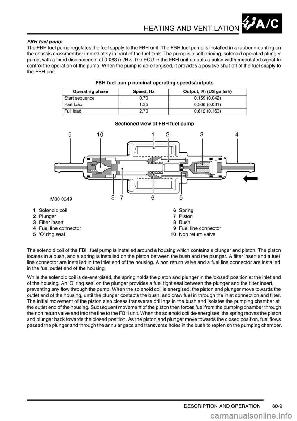
Sectioned view of FBH fuel pump
1Solenoid coil
2Plunger
3Filter insert
4Fuel line connector
5'O' ring seal6Spring
7Piston
8Bush
9Fuel line connector
10Non return valve
The solenoid coil of the FBH fuel pump is installed around a housing which contains a plunger and piston. The piston
locates in a bush, and a spring is installed on the piston between the bush and the plunger. A filter insert and a fuel
line connector are installed in the inlet end of the housing. A non return valve and a fuel line connector are installed
in the fuel outlet end of the housing.
While the solenoid coil is de-energised, the spring holds the piston and plunger in the 'closed' position at the inlet end
of the housing. An 'O' ring seal on the plunger provides a fuel tight seal between the plunger and the filter insert,
preventing any flow through the pump. When the solenoid coil is energised, the piston and plunger move towards the
outlet end of the housing, until the plunger contacts the bush, and draw fuel in through the inlet connection and filter.
The initial movement of the piston also closes transverse drillings in the bush and isolates the pumping chamber at
the outlet end of the housing. Subsequent movement of the piston then forces fuel from the pumping chamber through
the non return valve and into the line to the FBH unit. When the solenoid coil de-energises, the spring moves the piston
and plunger back towards the closed position. As the piston and plunger move towards the closed position, fuel flows
passed the plunger and through the annular gaps and transverse holes in the bush to replenish the pumping chamber.
Operating phase Speed, Hz Output, l/h (US galls/h)
Start sequence 0.70 0.159 (0.042)
Part load 1.35 0.306 (0.081)
Full load 2.70 0.612 (0.163)
Page 1599 of 1672

HARNESSES
86-7-28 REPAIRS
18.Secure multiplugs to steering column support
bracket and connect brake and clutch pedal
multiplugs.
19.Connect multiplugs to column switch and
passive coil.
20.Position passenger compartment fusebox,
connect multiplugs, fit fusebox to fascia and
secure with nut.
21.Connect ignition switch multiplug to fuse box.
22.With assistance feed LH side of harness into
engine bay.
23.Connect multiplugs to front door harness and
body harness.
24.Position earth headers to LH lower 'A' post and
secure with nuts.
25.Connect multiplugs to ECU pack.
26.Position harness in engine bay.
27.Connect and secure heated front screen
multiplugs.
28.Fit plenum molding.
+ HEATING AND VENTILATION,
REPAIRS, Plenum Air Intake.
29.Connect multiplugs to ABS sensor and fuel
cut-off switch.
30.Using draw string feed harness through inner
wing, remove draw string, connect repeater
lamp multiplug and fit lamp.
31.Connect multiplugs to ABS modulator.
32.Feed harness through to front panel.
33.Position body earth leads and secure with
bolts.
34.Connect washer reservoir multiplugs and
pipes, secure pipes with clips.
35.Secure fog lamp multiplug.
36.Secure earth header behind headlamp.
37.Connect multiplugs to headlamp level motor,
headlamp and side lamp.
38.Fit indicator lamp
+ LIGHTING, REPAIRS, Lamp - front
repeater.
39.Connect multiplug to LH horn.
40.Feed harness to ACE accelerometer, connect
multiplug and secure with cable ties.
41.Connect cruise control, ABS sensor and brake
fluid level switch multiplugs.
42.Connect engine harness multiplug and feed
harness along RH wing to fuse box.
43.Using draw string pull harness through inner
wing, remove draw string, connect repeater
lamp multiplug and fit lamp. 44.Connect chassis harness multiplugs.
45.Position engine bay fuse box and connect
multiplugs, fit fuse box and secure with screws.
46.Connect multiplugs to front of fuse box.
47.Position battery and starter cables and secure
with screws.
48.Fit fuse box cover.
49.Position earth lead and secure with nut.
50.Feed harness through to front panel.
51.Secure fog lamp multiplug.
52.Connect headlamp level motor, headlamp and
side lamp multiplugs.
53.Fit indicator lamp.
+ LIGHTING, REPAIRS, Lamp - front
repeater.
54.Secure harness to RH front panel.
55.Connect cooling fan and horn multiplug.
56.Secure harness to lower support rail.
57.Connect receiver drier and air temperature
sensor multiplugs.
58.Fit front bumper.
+ EXTERIOR FITTINGS, REPAIRS,
Bumper assembly - front.
59.Fit battery tray.
60.Fit air filter assembly.
+ ENGINE MANAGEMENT SYSTEM -
V8, REPAIRS, Air cleaner assembly.
61.Position both lower 'A' post trims and secure
with studs.
62.Fit heater assembly.
+ HEATING AND VENTILATION,
REPAIRS, Heater assembly - models with
air conditioning.
+ HEATING AND VENTILATION,
REPAIRS, Heater assembly - models
without air conditioning.
Page 1628 of 1672

INSTRUMENTS
DESCRIPTION AND OPERATION 88-1
INS TRUMENTS DESCRIPTION AND OPERAT ION
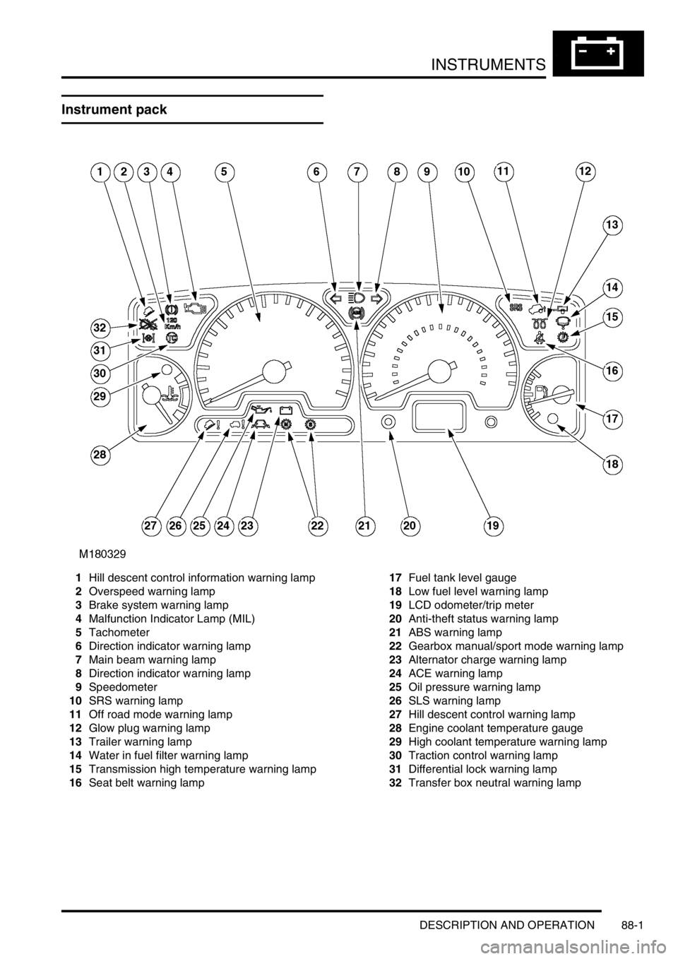
Instrument pack
1Hill descent control information warning lamp
2Overspeed warning lamp
3Brake system warning lamp
4Malfunction Indicator Lamp (MIL)
5Tachometer
6Direction indicator warning lamp
7Main beam warning lamp
8Direction indicator warning lamp
9Speedometer
10SRS warning lamp
11Off road mode warning lamp
12Glow plug warning lamp
13Trailer warning lamp
14Water in fuel filter warning lamp
15Transmission high temperature warning lamp
16Seat belt warning lamp17Fuel tank level gauge
18Low fuel level warning lamp
19LCD odometer/trip meter
20Anti-theft status warning lamp
21ABS warning lamp
22Gearbox manual/sport mode warning lamp
23Alternator charge warning lamp
24ACE warning lamp
25Oil pressure warning lamp
26SLS warning lamp
27Hill descent control warning lamp
28Engine coolant temperature gauge
29High coolant temperature warning lamp
30Traction control warning lamp
31Differential lock warning lamp
32Transfer box neutral warning lamp