2002 LAND ROVER DISCOVERY charging
[x] Cancel search: chargingPage 1366 of 1672
HEATING AND VENTILATION
REPAIRS 80-25
11.Disconnect both evaporator drain hoses.
12.Remove front heater ducting.
13.Remove 4 nuts and bolt securing heater
assembly, release heater assembly from
bulkhead grommet and remove from vehicle.
Refit
1.Position heater assembly to bulkhead, locate
heater in bulkhead grommet.
2.Fit nuts and bolt securing heater and tighten to
16 Nm (12 lbf.ft).
3.Position RH fascia support bracket, fit and
tighten nuts.
4.Fit front heater ducting.
5.Position centre console support bracket, fit and
tighten screws.
6.Connect evaporator drain hoses.
7.Position heater motor to heater casing, fit nuts
and bolt and tighten to 19 Nm (14 lbf.ft).
8.Connect multiplug heater motor.
9.Position rear heater ducting and secure with
screws.
10.Fit fascia.
+ INTERIOR TRIM COMPONENTS,
REPAIRS, Fascia.
11.Using new 'O' rings, position air conditioning
pipes to evaporator fit bolts and tighten to 5 Nm
(3.7 lbf.ft).
12.Position heater hoses and secure hose clips.
13.Recharge air conditioning system.
+ AIR CONDITIONING, REFRIGERANT
RECOVERY, RECYCLING AND
RECHARGING, Refrigerant recovery,
recycling and recharging.
14.Refill cooling system.
l
+ COOLING SYSTEM - V8,
ADJUSTMENTS, Drain and refill.
l
+ COOLING SYSTEM - Td5,
ADJUSTMENTS, Drain and refill.
Blower assembly
$% 80.20.12
Remove
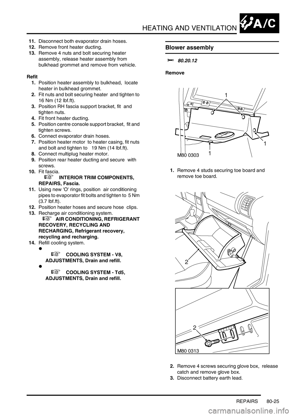
1.Remove 4 studs securing toe board and
remove toe board.
2.Remove 4 screws securing glove box, release
catch and remove glove box.
3.Disconnect battery earth lead.
Page 1378 of 1672
AIR CONDITIONING
DESCRIPTION AND OPERATION 82-5
To accomplish the transfer of heat, the refrigerant is circulated around the system, where it passes through two
pressure/temperature regimes. In each of the pressure/temperature regimes, the refrigerant changes state, during
which process maximum heat absorption or release occurs. The low pressure/temperature regime is from the
thermostatic expansion valve, through the evaporator to the compressor; the refrigerant decreases in pressure and
temperature at the thermostatic expansion valve, then changes state from liquid to vapour in the evaporator, to absorb
heat. The high pressure/temperature regime is from the compressor, through the condenser and receiver drier to the
thermostatic expansion valve; the refrigerant increases in pressure and temperature as it passes through the
compressor, then releases heat and changes state from vapour to liquid in the condenser.
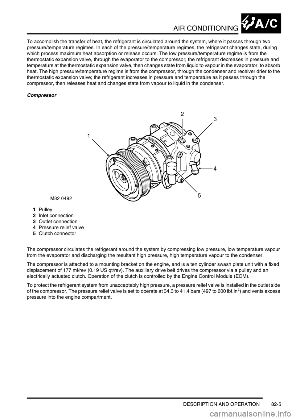
Compressor
1Pulley
2Inlet connection
3Outlet connection
4Pressure relief valve
5Clutch connector
The compressor circulates the refrigerant around the system by compressing low pressure, low temperature vapour
from the evaporator and discharging the resultant high pressure, high temperature vapour to the condenser.
The compressor is attached to a mounting bracket on the engine, and is a ten cylinder swash plate unit with a fixed
displacement of 177 ml/rev (0.19 US qt/rev). The auxiliary drive belt drives the compressor via a pulley and an
electrically actuated clutch. Operation of the clutch is controlled by the Engine Control Module (ECM).
To protect the refrigerant system from unacceptably high pressure, a pressure relief valve is installed in the outlet side
of the compressor. The pressure relief valve is set to operate at 34.3 to 41.4 bars (497 to 600 lbf.in
2) and vents excess
pressure into the engine compartment.
Page 1382 of 1672

AIR CONDITIONING
DESCRIPTION AND OPERATION 82-9
Evaporator
The evaporator is installed in the air inlet of the heater assembly and absorbs heat from the exterior or recirculated
inlet air. Low pressure, low temperature refrigerant changes from liquid to vapour in the evaporator, absorbing large
quantities of heat as it changes state.
Refrigerant lines
To maintain similar flow velocities around the system, the diameter of the refrigerant lines varies to suit the two
pressure/temperature regimes. The larger diameters are installed in the low pressure/temperature regime and the
smaller diameters are installed in the high pressure/temperature regime. Low and high pressure charging connections
are incorporated into the refrigerant lines for system servicing. Where rear AC is installed, connections for the rear
refrigerant lines are incorporated next to the charging connections.
Page 1402 of 1672
AIR CONDITIONING
REFRIGERANT RECOVERY, RECYCLING AND RECHARGING 82-29
REFRIGERANT RECOVERY, RECYCLING AND RECHARGING
Refrigerant recovery, recycling and
recharging
$% 82.30.02
Recovery
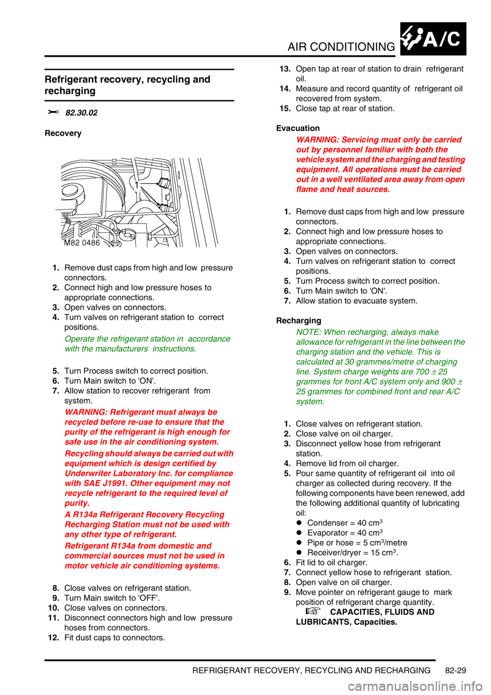
1.Remove dust caps from high and low pressure
connectors.
2.Connect high and low pressure hoses to
appropriate connections.
3.Open valves on connectors.
4.Turn valves on refrigerant station to correct
positions.
Operate the refrigerant station in accordance
with the manufacturers instructions.
5.Turn Process switch to correct position.
6.Turn Main switch to 'ON'.
7.Allow station to recover refrigerant from
system.
WARNING: Refrigerant must always be
recycled before re-use to ensure that the
purity of the refrigerant is high enough for
safe use in the air conditioning system.
Recycling should always be carried out with
equipment which is design certified by
Underwriter Laboratory Inc. for compliance
with SAE J1991. Other equipment may not
recycle refrigerant to the required level of
purity.
A R134a Refrigerant Recovery Recycling
Recharging Station must not be used with
any other type of refrigerant.
Refrigerant R134a from domestic and
commercial sources must not be used in
motor vehicle air conditioning systems.
8.Close valves on refrigerant station.
9.Turn Main switch to 'OFF'.
10.Close valves on connectors.
11.Disconnect connectors high and low pressure
hoses from connectors.
12.Fit dust caps to connectors. 13.Open tap at rear of station to drain refrigerant
oil.
14.Measure and record quantity of refrigerant oil
recovered from system.
15.Close tap at rear of station.
Evacuation
WARNING: Servicing must only be carried
out by personnel familiar with both the
vehicle system and the charging and testing
equipment. All operations must be carried
out in a well ventilated area away from open
flame and heat sources.
1.Remove dust caps from high and low pressure
connectors.
2.Connect high and low pressure hoses to
appropriate connections.
3.Open valves on connectors.
4.Turn valves on refrigerant station to correct
positions.
5.Turn Process switch to correct position.
6.Turn Main switch to 'ON'.
7.Allow station to evacuate system.
Recharging
NOTE: When recharging, always make
allowance for refrigerant in the line between the
charging station and the vehicle. This is
calculated at 30 grammes/metre of charging
line. System charge weights are 700
± 25
grammes for front A/C system only and 900
±
25 grammes for combined front and rear A/C
system.
1.Close valves on refrigerant station.
2.Close valve on oil charger.
3.Disconnect yellow hose from refrigerant
station.
4.Remove lid from oil charger.
5.Pour same quantity of refrigerant oil into oil
charger as collected during recovery. If the
following components have been renewed, add
the following additional quantity of lubricating
oil:
lCondenser = 40 cm
3
lEvaporator = 40 cm3
lPipe or hose = 5 cm3/metre
lReceiver/dryer = 15 cm3.
6.Fit lid to oil charger.
7.Connect yellow hose to refrigerant station.
8.Open valve on oil charger.
9.Move pointer on refrigerant gauge to mark
position of refrigerant charge quantity.
+ CAPACITIES, FLUIDS AND
LUBRICANTS, Capacities.
Page 1403 of 1672

AIR CONDITIONING
82-30REFRIGERANT RECOVERY, RECYCLING AND RECHARGING
10.Slowly open correct valve on refrigerant station
and allow vacuum to pull refrigerant into
system.
11.Close valve on refrigerant station when correct
amount of refrigerant has been drawn into air
conditioning system.
12.Turn Main switch to 'OFF'.
13.Close valves on connectors.
14.Disconnect high and low pressure hoses from
connectors.
15.Fit dust caps to connectors.
Page 1404 of 1672
AIR CONDITIONING
REPAIRS 82-31
REPAIRS
Compressor - diesel
$% 82.10.20
Remove
1.Remove engine acoustic cover.
2.Depressurise air conditioning system.
+ AIR CONDITIONING, REFRIGERANT
RECOVERY, RECYCLING AND
RECHARGING, Refrigerant recovery,
recycling and recharging.
3.Remove auxiliary drive belt.
+ CHARGING AND STARTING,
REPAIRS, Belt - auxiliary drive.
4.Drain cooling system.
+ COOLING SYSTEM - Td5,
ADJUSTMENTS, Drain and refill.
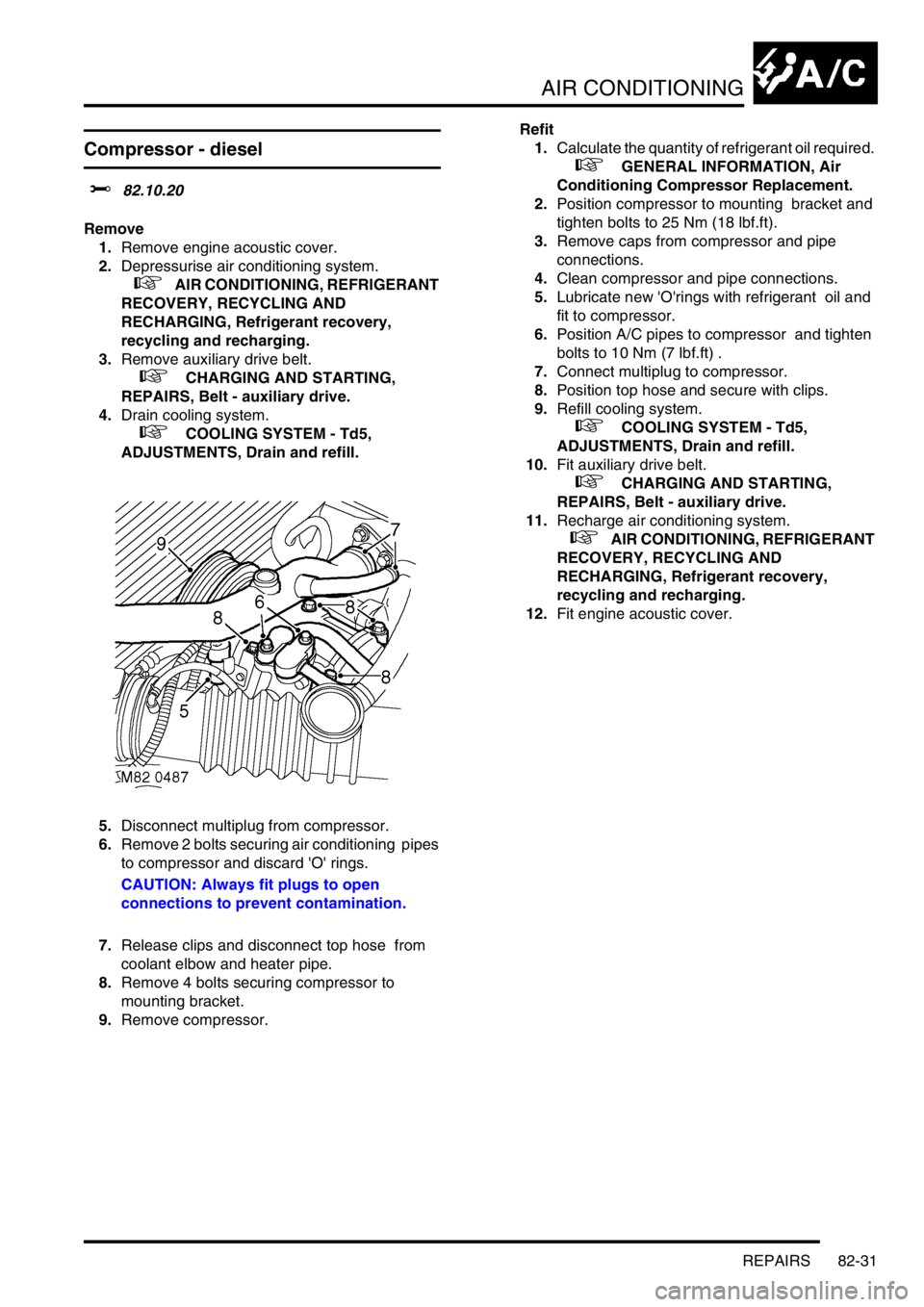
5.Disconnect multiplug from compressor.
6.Remove 2 bolts securing air conditioning pipes
to compressor and discard 'O' rings.
CAUTION: Always fit plugs to open
connections to prevent contamination.
7.Release clips and disconnect top hose from
coolant elbow and heater pipe.
8.Remove 4 bolts securing compressor to
mounting bracket.
9.Remove compressor.Refit
1.Calculate the quantity of refrigerant oil required.
+ GENERAL INFORMATION, Air
Conditioning Compressor Replacement.
2.Position compressor to mounting bracket and
tighten bolts to 25 Nm (18 lbf.ft).
3.Remove caps from compressor and pipe
connections.
4.Clean compressor and pipe connections.
5.Lubricate new 'O'rings with refrigerant oil and
fit to compressor.
6.Position A/C pipes to compressor and tighten
bolts to 10 Nm (7 lbf.ft) .
7.Connect multiplug to compressor.
8.Position top hose and secure with clips.
9.Refill cooling system.
+ COOLING SYSTEM - Td5,
ADJUSTMENTS, Drain and refill.
10.Fit auxiliary drive belt.
+ CHARGING AND STARTING,
REPAIRS, Belt - auxiliary drive.
11.Recharge air conditioning system.
+ AIR CONDITIONING, REFRIGERANT
RECOVERY, RECYCLING AND
RECHARGING, Refrigerant recovery,
recycling and recharging.
12.Fit engine acoustic cover.
Page 1405 of 1672
AIR CONDITIONING
82-32REPAIRS
Compressor - V8
$% 82.10.20
Remove
1.Depressurise air conditioning system.
+ AIR CONDITIONING, REFRIGERANT
RECOVERY, RECYCLING AND
RECHARGING, Refrigerant recovery,
recycling and recharging.
2.Remove auxiliary drive belt.
+ CHARGING AND STARTING,
REPAIRS, Belt - auxiliary drive.
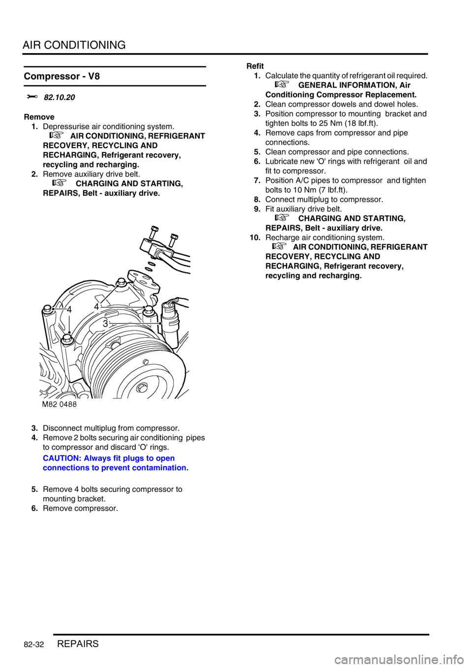
3.Disconnect multiplug from compressor.
4.Remove 2 bolts securing air conditioning pipes
to compressor and discard 'O' rings.
CAUTION: Always fit plugs to open
connections to prevent contamination.
5.Remove 4 bolts securing compressor to
mounting bracket.
6.Remove compressor.Refit
1.Calculate the quantity of refrigerant oil required.
+ GENERAL INFORMATION, Air
Conditioning Compressor Replacement.
2.Clean compressor dowels and dowel holes.
3.Position compressor to mounting bracket and
tighten bolts to 25 Nm (18 lbf.ft).
4.Remove caps from compressor and pipe
connections.
5.Clean compressor and pipe connections.
6.Lubricate new 'O' rings with refrigerant oil and
fit to compressor.
7.Position A/C pipes to compressor and tighten
bolts to 10 Nm (7 lbf.ft).
8.Connect multiplug to compressor.
9.Fit auxiliary drive belt.
+ CHARGING AND STARTING,
REPAIRS, Belt - auxiliary drive.
10.Recharge air conditioning system.
+ AIR CONDITIONING, REFRIGERANT
RECOVERY, RECYCLING AND
RECHARGING, Refrigerant recovery,
recycling and recharging.
Page 1406 of 1672
AIR CONDITIONING
REPAIRS 82-33
Fan - condenser
$% 82.15.01
Remove
1.Remove front grille.
+ EXTERIOR FITTINGS, REPAIRS,
Grille - front - up to 03MY.
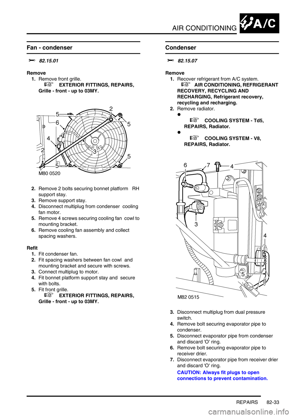
2.Remove 2 bolts securing bonnet platform RH
support stay.
3.Remove support stay.
4.Disconnect multiplug from condenser cooling
fan motor.
5.Remove 4 screws securing cooling fan cowl to
mounting bracket.
6.Remove cooling fan assembly and collect
spacing washers.
Refit
1.Fit condenser fan.
2.Fit spacing washers between fan cowl and
mounting bracket and secure with screws.
3.Connect multiplug to motor.
4.Fit bonnet platform support stay and secure
with bolts.
5.Fit front grille.
+ EXTERIOR FITTINGS, REPAIRS,
Grille - front - up to 03MY.
Condenser
$% 82.15.07
Remove
1.Recover refrigerant from A/C system.
+ AIR CONDITIONING, REFRIGERANT
RECOVERY, RECYCLING AND
RECHARGING, Refrigerant recovery,
recycling and recharging.
2.Remove radiator.
l
+ COOLING SYSTEM - Td5,
REPAIRS, Radiator.
l
+ COOLING SYSTEM - V8,
REPAIRS, Radiator.
3.Disconnect multiplug from dual pressure
switch.
4.Remove bolt securing evaporator pipe to
condenser.
5.Disconnect evaporator pipe from condenser
and discard 'O' ring.
6.Remove bolt securing evaporator pipe to
receiver drier.
7.Disconnect evaporator pipe from receiver drier
and discard 'O' ring.
CAUTION: Always fit plugs to open
connections to prevent contamination.