2002 LAND ROVER DISCOVERY ECO mode
[x] Cancel search: ECO modePage 1173 of 1672

INTERIOR TRIM COMPONENTS
76-3-20 REPAIRS
Headlining
$% 76.64.15.21
Remove
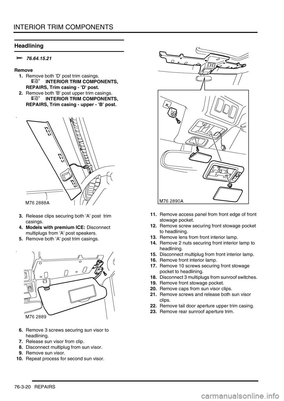
1.Remove both 'D' post trim casings.
+ INTERIOR TRIM COMPONENTS,
REPAIRS, Trim casing - 'D' post.
2.Remove both 'B' post upper trim casings.
+ INTERIOR TRIM COMPONENTS,
REPAIRS, Trim casing - upper - 'B' post.
3.Release clips securing both 'A' post trim
casings.
4. Models with premium ICE: Disconnect
multiplugs from 'A' post speakers.
5.Remove both 'A' post trim casings.
6.Remove 3 screws securing sun visor to
headlining.
7.Release sun visor from clip.
8.Disconnect multiplug from sun visor.
9.Remove sun visor.
10.Repeat process for second sun visor. 11.Remove access panel from front edge of front
stowage pocket.
12.Remove screw securing front stowage pocket
to headlining.
13.Remove lens from front interior lamp.
14.Remove 2 nuts securing front interior lamp to
headlining.
15.Disconnect multiplug from front interior lamp.
16.Remove front interior lamp.
17.Remove 10 screws securing front stowage
pocket to headlining.
18.Disconnect 3 multiplugs from sunroof switches.
19.Remove front stowage pocket.
20.Remove caps from sun visor clips.
21.Remove screws and release both sun visor
clips.
22.Remove tail door aperture upper trim casing.
23.Remove rear sunroof aperture trim.
Page 1175 of 1672

INTERIOR TRIM COMPONENTS
76-3-22 REPAIRS
38.Remove 7 nuts securing each stowage pocket
to headlining and collect mounting plates.
39.Remove both pockets from headlining.
40.Remove 8 screws securing rear console to
headlining and collect 3 mounting plates.
41.Remove rear console from headlining.
Refit
1.Fit rear console and mounting plates to
headlining.
2.Fit and tighten nuts securing rear console to
headlining.
3.Fit both stowage pockets and mounting plates
to headlining.
4.Fit and tighten nuts securing stowage pockets
to headlining.
5. Models with rear A/C:
aFit 3 central air vents to headlining.
bFit 2 rear air vents to headlining.
cFit foam pads to air vents.
6.With assistance, position headlining in vehicle.
7.Fit and tighten screw securing centre of
headlining to roof.
8.Connect multiplug to rear sunroof switch.
9.Fit rear sunroof switch to rear console.
10.Fit clips securing rear edge of headlining to
sunroof. 11.Position rear interior lamp to headlining and
connect multiplug.
12.Fit rear interior lamp to headlining.
13. Models with rear A/C:
aPosition rear A/C control panel to headlining
and connect multiplugs and Lucar
connectors.
bFit rear A/C control panel to headlining.
14. Models with volumetric alarm: Connect
multiplug to front volumetric sensor and fit
sensor to headlining.
15.Fit grab handles to headlining and secure with
bolts.
16.Fit end caps to grab handles.
17.Fit front sunroof aperture trim.
18.Fit rear sunroof aperture trim.
19.Fit tail door aperture upper trim casing.
20.Fit sun visor clips to headlining and secure with
screws.
21.Fit caps to sun visor clips.
22.Position front stowage pocket to headlining and
connect multiplugs to sunroof switches.
23.Fit and tighten 10 screws securing front
stowage pocket to headlining.
24.Connect multiplug to front interior lamp.
25.Fit front interior lamp to headlining and secure
with nuts.
26.Fit lens to front interior lamp.
27.Fit and tighten screw securing front stowage
pocket to headlining.
28.Fit access panel to front edge of front stowage
pocket.
29.Position sun visor to headlining and secure to
clip.
30.Connect multiplug to sun visor.
31.Fit and tighten screws securing sun visor to
headlining.
32.Repeat process for second sun visor.
33. Models with premium ICE: Position both 'A'
post trim casings and connect multiplugs to
speakers.
34.Fit both trim casings to 'A' posts and secure
with clips.
35.Fit both 'B' post upper trim casings.
+ INTERIOR TRIM COMPONENTS,
REPAIRS, Trim casing - upper - 'B' post.
36.Fit both 'D' post trim casings.
+ INTERIOR TRIM COMPONENTS,
REPAIRS, Trim casing - 'D' post.
Page 1227 of 1672

SUNROOF
76-6-12 DESCRIPTION AND OPERATION
Operation
Ignition switched-off timeout
There are three timeout modes for operating the sunroof assemblies after the ignition is switched off. The BCU
determines the vehicle's timeout mode. The three modes are:
lWhen the ignition is switched off, no sunroof operation is permitted.
lWhen the ignition is switched off, sunroof remains functional for 45 seconds or until the driver door is opened.
lWhen the ignition is switched off, sunroof remains functional for 45 seconds or until any door is opened.
Sunroof open and close
Both sunroof assemblies operate in the same manner. The front sunroof assembly has one switch while there are
two switches to control rear sunroof assembly, a rear sunroof front switch and a rear sunroof rear switch.
The sunroof ECU monitors the position of the sunroof microswitch to determine if the sunroof is to be tilted or opened.
In order for the sunroof to operate, either of the following conditions must exist:
lIgnition switch in position II.
lIgnition switched from on to off, doors closed (this may enable the system to operate for 45 seconds after the
ignition is switched off, or until a door is opened).
When the sunroof is closed, pressing the rear of the sunroof switch causes the sunroof ECU to operate the sunroof
motor and open the sunroof. When the sunroof opens, the sunroof microswitch opens. The sunroof continues to
open until the switch is released or the sunroof reaches the fully open position.
When the sunroof is open, pressing the front of the sunroof switch causes the sunroof ECU to operate the sunroof
motor and close the sunroof. The sunroof ECU continues to operate the motor until the sunroof microswitch closes.
This indicates to the sunroof ECU that the sunroof is fully closed.
Sunroof tilt
Both sunroof assemblies operate in the same manner. The front sunroof assembly has one switch while there are
two switches to control rear sunroof assembly, a rear sunroof front switch and a rear sunroof rear switch.
The sunroof ECU monitors the position of the sunroof microswitch to determine if the sunroof is to be tilted or opened.
In order for the sunroof to operate, either of the following conditions must exist.
lIgnition in position II.
lIgnition switched from on to off, doors closed (this may enable the system to operate for 45 seconds after the
ignition is switched off, or until a door is opened).
When the sunroof is closed and the front of the sunroof switch is pressed, the sunroof ECU detects the combination
of closed microswitch and front of sunroof switch being pressed and tilts the rear of the sunroof. This causes the
microswitch to open. The sunroof continues to open until the switch is released or the sunroof reaches the fully open
position.
When the sunroof is tilted and the rear of the sunroof switch is pressed, the sunroof ECU detects the combination of
open microswitch and rear of sunroof switch and closes the sunroof until the microswitch closes. This indicates to the
sunroof ECU that the sunroof is fully closed.
Rear sunroof isolation
The rear sunroof isolation switch prevents the rear sunroof rear switch from operating the rear sunroof. This can be
used to prevent small children sitting in the rear seat from playing with the rear sunroof.
Pressing the rear sunroof isolation switch opens the circuit between the rear sunroof rear switch and the sunroof ECU.
The sunroof ECU ignores the rear sunroof switch until the rear sunroof isolation switch is pressed and the circuit
closes.
Page 1276 of 1672

PANEL REPAIRS
REPAIRS 77-2-27
11.Fit headlamp.
+ LIGHTING, REPAIRS, Headlamp - up
to 03MY.
12. Diesel models: Fit gearbox fluid cooler.
13. Models with A/C: Fit condensor.
+ AIR CONDITIONING, REPAIRS,
Condenser.
14.Fit washer reservoir.
+ WIPERS AND WASHERS, REPAIRS,
Reservoir - washer - up to 03MY.
15.Connect leads/multiplug to alternator.
16.Connect battery leads, negative lead last.
Valance upper assembly - LH
In this procedure, the front wing, the valance outer
reinforcement and the bonnet alarm switch mounting
bracket are replaced in conjunction with the LH
valance upper assembly.
Remove
1.Disconnect both battery leads, negative lead
first.
2.Disconnect leads/multiplug from alternator.
3.Remove front wing.
+ EXTERIOR FITTINGS, REPAIRS,
Wing - front - up to 03MY.
4.Remove air filter assembly.
+ ENGINE MANAGEMENT SYSTEM -
V8, REPAIRS, Air cleaner assembly.
+ ENGINE MANAGEMENT SYSTEM -
Td5, REPAIRS, Air filter assembly.
5.Remove PAS/ACE reservoir.
6.Remove ABS modulator.
+ BRAKES, REPAIRS, Modulator unit
- ABS.
7.Remove brake pipes from valance.
8.Release harness from valance and position
aside.
9. Models with A/C: Depressurise A/C system
and remove pipes from valance.
+ AIR CONDITIONING, REFRIGERANT
RECOVERY, RECYCLING AND
RECHARGING, Refrigerant recovery,
recycling and recharging.
Page 1277 of 1672

PANEL REPAIRS
77-2-28 REPAIRS
Repair
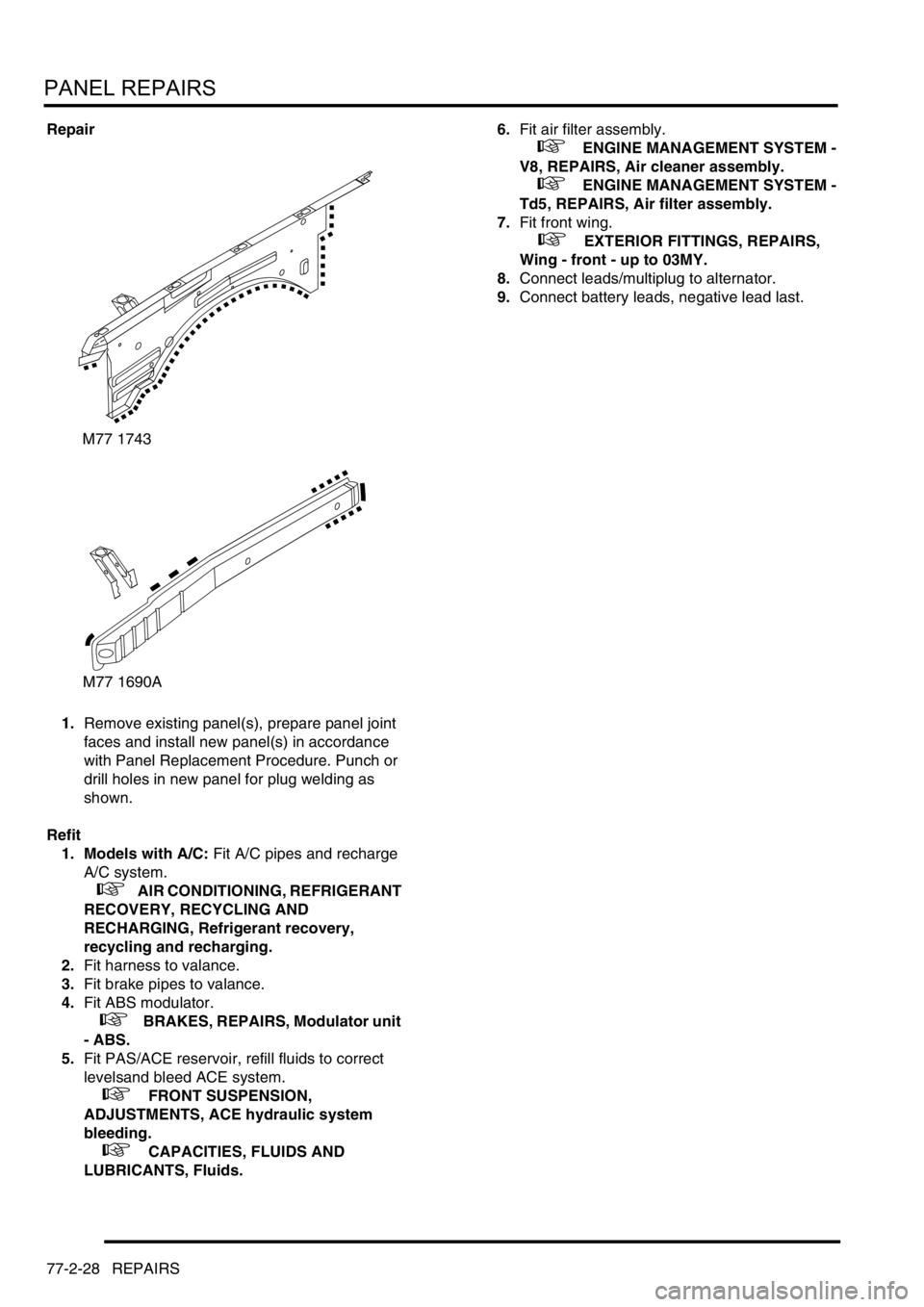
1.Remove existing panel(s), prepare panel joint
faces and install new panel(s) in accordance
with Panel Replacement Procedure. Punch or
drill holes in new panel for plug welding as
shown.
Refit
1. Models with A/C: Fit A/C pipes and recharge
A/C system.
+ AIR CONDITIONING, REFRIGERANT
RECOVERY, RECYCLING AND
RECHARGING, Refrigerant recovery,
recycling and recharging.
2.Fit harness to valance.
3.Fit brake pipes to valance.
4.Fit ABS modulator.
+ BRAKES, REPAIRS, Modulator unit
- ABS.
5.Fit PAS/ACE reservoir, refill fluids to correct
levelsand bleed ACE system.
+ FRONT SUSPENSION,
ADJUSTMENTS, ACE hydraulic system
bleeding.
+ CAPACITIES, FLUIDS AND
LUBRICANTS, Fluids.6.Fit air filter assembly.
+ ENGINE MANAGEMENT SYSTEM -
V8, REPAIRS, Air cleaner assembly.
+ ENGINE MANAGEMENT SYSTEM -
Td5, REPAIRS, Air filter assembly.
7.Fit front wing.
+ EXTERIOR FITTINGS, REPAIRS,
Wing - front - up to 03MY.
8.Connect leads/multiplug to alternator.
9.Connect battery leads, negative lead last.
M77 1743
M77 1690A
Page 1279 of 1672

PANEL REPAIRS
77-2-30 REPAIRS
Valance upper assembly (front section) -
LH
In this procedure, the front wing, the valance outer
reinforcement (front section) and the bonnet alarm
switch mounting bracket are replaced in conjunction
with the LH valance upper assembly (front section).
Remove
1.Disconnect both battery leads, negative lead
first.
2.Disconnect leads/multiplug from alternator.
3.Remove front wing.
+ EXTERIOR FITTINGS, REPAIRS,
Wing - front - up to 03MY.
4.Remove air filter assembly.
+ ENGINE MANAGEMENT SYSTEM -
Td5, REPAIRS, Air filter assembly.
+ ENGINE MANAGEMENT SYSTEM -
V8, REPAIRS, Air cleaner assembly.
5.Remove PAS/ACE reservoir.
6.Remove ABS modulator.
+ BRAKES, REPAIRS, Modulator unit
- ABS.
7.Release harness from valance and position
aside.
8. Models with A/C: Depressurise A/C system
and remove pipes from valance.
+ AIR CONDITIONING, REFRIGERANT
RECOVERY, RECYCLING AND
RECHARGING, Refrigerant recovery,
recycling and recharging.Repair
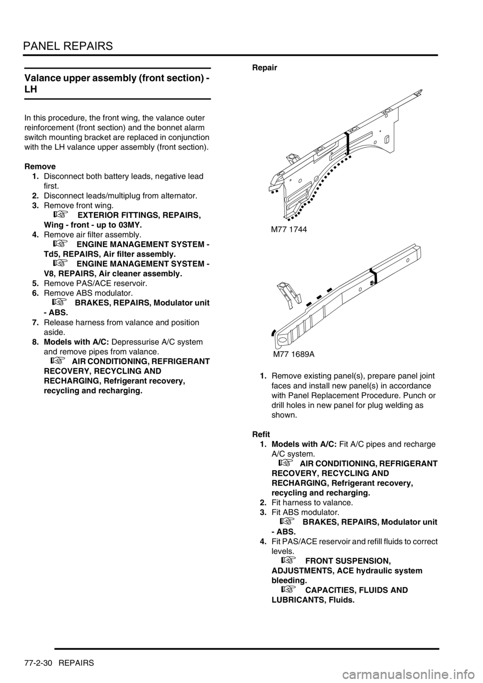
1.Remove existing panel(s), prepare panel joint
faces and install new panel(s) in accordance
with Panel Replacement Procedure. Punch or
drill holes in new panel for plug welding as
shown.
Refit
1. Models with A/C: Fit A/C pipes and recharge
A/C system.
+ AIR CONDITIONING, REFRIGERANT
RECOVERY, RECYCLING AND
RECHARGING, Refrigerant recovery,
recycling and recharging.
2.Fit harness to valance.
3.Fit ABS modulator.
+ BRAKES, REPAIRS, Modulator unit
- ABS.
4.Fit PAS/ACE reservoir and refill fluids to correct
levels.
+ FRONT SUSPENSION,
ADJUSTMENTS, ACE hydraulic system
bleeding.
+ CAPACITIES, FLUIDS AND
LUBRICANTS, Fluids.
M77 1744
M77 1689A
Page 1286 of 1672

PANEL REPAIRS
REPAIRS 77-2-37
Sill outer assembly
Remove
1.Disconnect both battery leads, negative lead
first.
2.Disconnect leads/multiplug from alternator.
3.Remove RH or LH front wing.
+ EXTERIOR FITTINGS, REPAIRS,
Wing - front - up to 03MY.
4.Remove RH or LH front door.
+ DOORS, REPAIRS, Door - front.
5.Remove RH or LH rear door.
+ DOORS, REPAIRS, Door - rear.
6.Remove RH or LH sill finisher.
7.Remove RH or LH 'A' post inner lower
finishers.
8.Remove RH or LH front seat.
+ SEATS, REPAIRS, Seat - front.
9. LH side: Remove power amplifier and EAT
ECU.
+ IN CAR ENTERTAINMENT,
REPAIRS, Amplifier - power.
10. RH side: Remove CD autochanger.
+ IN CAR ENTERTAINMENT,
REPAIRS, CD autochanger.
11.Remove rear seats.
+ SEATS, REPAIRS, Seat - rear.
12.Remove RH or LH front seat belt.
+ RESTRAINT SYSTEMS, REPAIRS,
Seat belt - front.
13.Remove tread plates from front and rear door
apertures.
14.Release carpet and position aside.
15.Remove front and rear door aperture seals.
16.Release relevant wiring from 'A' post, 'B/C' post
and sill areas, and position aside.
17.Remove loadspace lower trim casing.
+ INTERIOR TRIM COMPONENTS,
REPAIRS, Trim casing - side - loadspace.
18. RH side: Remove lower ACE accelerometer.
+ FRONT SUSPENSION, REPAIRS,
Accelerometer - ACE - lower.
19. LH side: Remove SLS air compressor unit.
+ REAR SUSPENSION, REPAIRS,
Compressor unit - air - SLS.
20. Models with rear A/C: Recover refrigerant
from A/C system and remove A/C pipes from
LH sill.
+ AIR CONDITIONING, REFRIGERANT
RECOVERY, RECYCLING AND
RECHARGING, Refrigerant recovery,
recycling and recharging.
21.Remove 2 bolts securing body to chassis.Repair
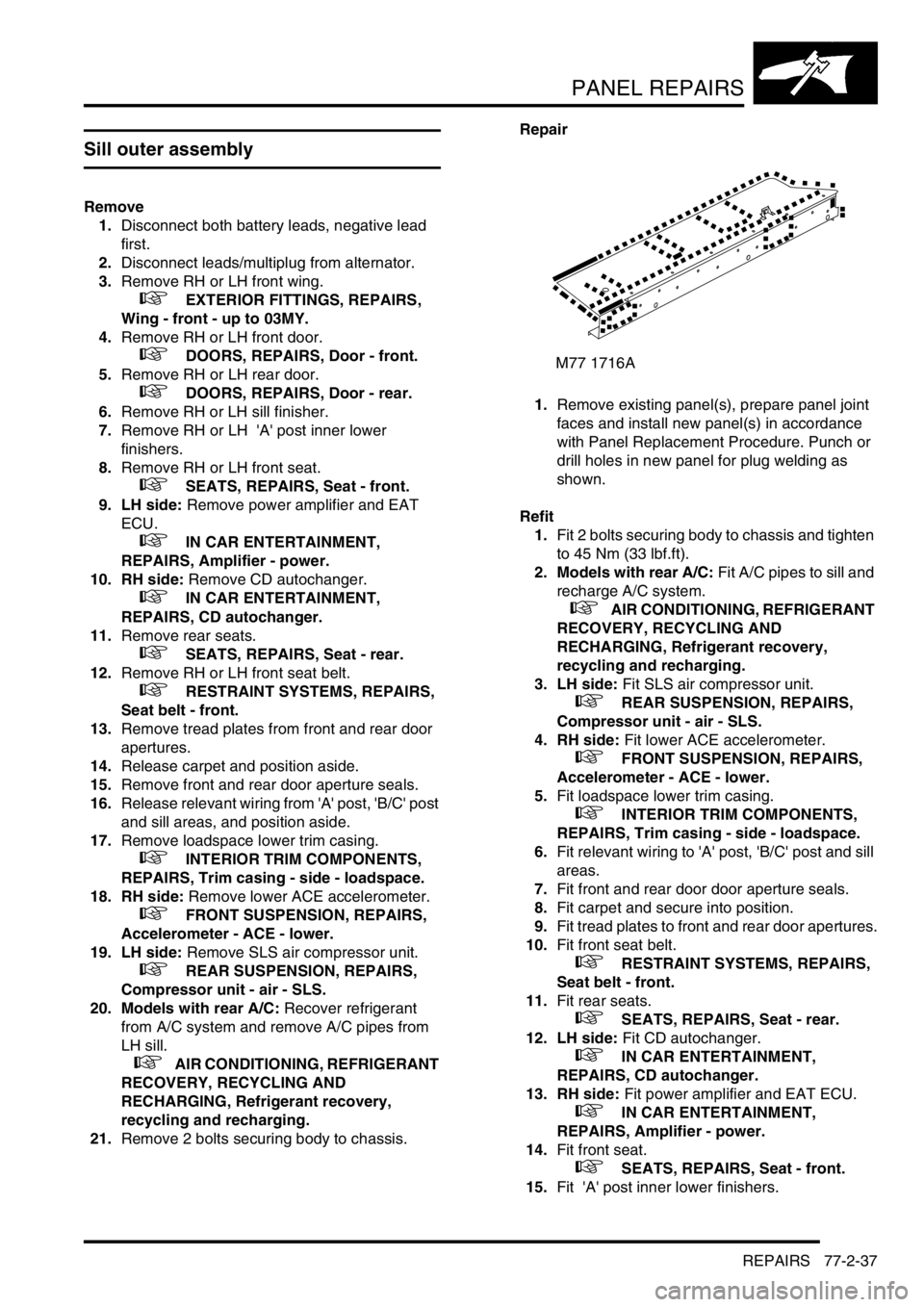
1.Remove existing panel(s), prepare panel joint
faces and install new panel(s) in accordance
with Panel Replacement Procedure. Punch or
drill holes in new panel for plug welding as
shown.
Refit
1.Fit 2 bolts securing body to chassis and tighten
to 45 Nm (33 lbf.ft).
2. Models with rear A/C: Fit A/C pipes to sill and
recharge A/C system.
+ AIR CONDITIONING, REFRIGERANT
RECOVERY, RECYCLING AND
RECHARGING, Refrigerant recovery,
recycling and recharging.
3. LH side: Fit SLS air compressor unit.
+ REAR SUSPENSION, REPAIRS,
Compressor unit - air - SLS.
4. RH side: Fit lower ACE accelerometer.
+ FRONT SUSPENSION, REPAIRS,
Accelerometer - ACE - lower.
5.Fit loadspace lower trim casing.
+ INTERIOR TRIM COMPONENTS,
REPAIRS, Trim casing - side - loadspace.
6.Fit relevant wiring to 'A' post, 'B/C' post and sill
areas.
7.Fit front and rear door door aperture seals.
8.Fit carpet and secure into position.
9.Fit tread plates to front and rear door apertures.
10.Fit front seat belt.
+ RESTRAINT SYSTEMS, REPAIRS,
Seat belt - front.
11.Fit rear seats.
+ SEATS, REPAIRS, Seat - rear.
12. LH side: Fit CD autochanger.
+ IN CAR ENTERTAINMENT,
REPAIRS, CD autochanger.
13. RH side: Fit power amplifier and EAT ECU.
+ IN CAR ENTERTAINMENT,
REPAIRS, Amplifier - power.
14.Fit front seat.
+ SEATS, REPAIRS, Seat - front.
15.Fit 'A' post inner lower finishers.
M77 1716A
Page 1354 of 1672

HEATING AND VENTILATION
DESCRIPTION AND OPERATION 80-13
Operation
Air distribution
Turning the distribution knob on the control panel turns the control flaps in the heater assembly to direct air to the
corresponding fascia and footwell outlets.
Air temperature
Turning the LH or RH temperature knob on the control panel turns the related blend flaps in the heater assembly. The
blend flaps vary the proportion of air going through the cold air bypass and the heater matrix. The proportion varies,
between full bypass no heat and no bypass full heat, to correspond with the position of the temperature knob.
Blower speed
The blower can be selected off or to run at one of four speeds. While the ignition is on, when the blower switch is set
to positions 1, 2, 3, or 4, ignition power energises the blower relay, which supplies battery power to the blower. At
switch positions 1, 2 and 3, the blower switch also connects the blower to different earth paths through the resistor
pack, to produce corresponding differences of blower operating voltage and speed. At position 4, the blower switch
connects an earth direct to the blower, bypassing the resistor pack, and full battery voltage drives the blower at
maximum speed.
Fresh/Recirculated inlet air
When the recirculated air switch is latched in, the amber indicator LED in the switch illuminates and an earth is
connected to the recirculated air side of the fresh/recirculated air servo motor. The fresh/recirculated air servo motor
then turns the control flaps in the air inlet duct to close the fresh air inlet and open the recirculated air inlets.
When the latch of the recirculated air switch is released, the amber indicator LED in the switch extinguishes and the
earth is switched from the recirculated air side to the fresh air side of the fresh/recirculated air servo motor. The fresh/
recirculated air servo motor then turns the control flaps in the air inlet duct to open the fresh air inlet and close the
recirculated air inlets.
FBH system (where fitted)
The FBH system operates only while the engine is running and the ambient temperature is less than 5
°C (41 °F).
With the engine running and the ambient temperature below 5
°C (41 °F), the air temperature sensor connects the
alternator power supply to the ECU in the FBH unit. On receipt of the alternator power supply, the ECU starts the
circulation pump and, depending on the input from the temperature sensor in the heat exchanger, enters either a
standby or active mode of operation. If the heat exchanger casing temperature is 65
°C (149 °F) or above, the ECU
enters a standby mode of operation. If the heat exchanger casing temperature is below 65
°C (149 °F), the ECU enters
an active mode of operation. In the standby mode, the ECU monitors the heat exchanger casing temperature and
enters the active mode if it drops below 65
°C (149 °F). In the active mode, the ECU initiates a start sequence and
then operates the system at full or part load combustion to provide the required heat input to the coolant.
Start sequence
At the beginning of the start sequence the ECU energises the glow plug function of the glow plug/flame sensor, to
preheat the combustion chamber, and starts the combustion air fan at slow speed. After 30 seconds, the ECU
energises the FBH fuel pump at the starting sequence speed. The fuel delivered by the FBH fuel pump evaporates in
the combustion chamber, mixes with air from the combustion air fan and is ignited by the glow plug/flame sensor. The
ECU then progressively increases the speed of the FBH fuel pump and the combustion air fan to either part or full
load speed, as required by the system. Once full or part load speed is achieved, the ECU switches the glow plug/flame
sensor from the glow plug function to the flame sensing function to monitor combustion. From the beginning of the
start sequence to stable combustion takes approximately 90 seconds for a start to part load combustion and 150
seconds for a start to full load combustion.