2002 LAND ROVER DISCOVERY ECU
[x] Cancel search: ECUPage 999 of 1672

FRONT SUSPENSION
60-60 REPAIRS
22. Valve block to reservoir pipe: Release fluid
return pipe from clip on LH chassis member.
23.Remove bolt securing pipe clamp to RH
chassis member and remove clamp.
24.Release harness clip from RH suspension
turret. 25.Remove nut securing pipe clamp to bracket on
RH suspension turret and remove clamp.
26.Release pipe from isolator above chassis RH
front outrigger.
27.Cut pipe at suitable point near suspension
turret.
28.Remove and discard front and rear sections of
pipe.
Refit
1.Fit both sections of new pipe to vehicle.
2.Ensure 'O' ring is fitted to union on front section
of pipe.
3.Push both sections of pipe together squarely
and tighten union nut to 16 Nm (12 lbf.ft).
4.Locate pipe in isolator above chassis RH front
outrigger. Fit cable tie around isolator to secure
pipe.
5. Valve block to reservoir pipe: Fit clip to
reservoir hose, connect hose to reservoir and
secure with clip.
6. Pump to valve block pipe: Ensure pipe banjo
and ACE pump connections are clean, fit new
sealing washers, align banjo to pump and
tighten bolt to 29 Nm (21 lbf.ft).
Page 1000 of 1672

FRONT SUSPENSION
REPAIRS 60-61
7.Fit pipe clamps to pipes, align clamps to
chassis front cross member and fit bolts.
8. Valve block to reservoir pipe: F it pi pe to c li p
on LH chassis member.
9.Fit pipe clamp to pipes, align clamp to
suspension turret and secure with nut.
10.Fit pipe clamp to pipes, align clamp to RH
chassis member and secure with bolt.
11.Align and secure harness to suspension turret.
12.Fit thermostat housing and hoses and secure
hoses with clips.
13.Fit turbocharger outlet pipe and secure hoses
with clips.
14.Connect turbocharger pressure sensing hose
and secure with clip.
15.Fit 'O' ring to air cleaner.
16.Fit air hose to turbocharger and tighten clip.
17.Fit air flow meter to air cleaner and secure with
clips.
18.Connect multiplug to air flow meter.
19.Fit lower half of fan cowl and secure with
screws.
20.Fit viscous fan.
+ COOLING SYSTEM - Td5, REPAIRS,
Fan - viscous.
21.Fit RH splash shield and secure with screws.
22.Fit road wheel.
23.Fit valve block.
+ FRONT SUSPENSION, REPAIRS,
Valve block - ACE.
24.Renew ACE high pressure filter
+ FRONT SUSPENSION, REPAIRS,
Filter - high pressure - ACE.
25.Lower vehicle.
26.Fill cooling system.
+ COOLING SYSTEM - Td5,
ADJUSTMENTS, Drain and refill.
Pipe assembly - valve block to rear
actuator - ACE
$% 60.60.33
CAUTION: The ACE hydraulic system is
extremely sensitive to the ingress of dirt or
debris. The smallest amount could render the
system unserviceable. It is imperative that the
following precautions are taken.
lACE components are thoroughly cleaned
externally before work commences;
lall opened pipe and module ports are
capped immediately;
lall fluid is stored in and administered
through clean containers.
Remove
1.Raise vehicle on a ramp.
2.Position container under valve block to collect
fluid spillage.
3.Remove 2 bolts securing 2 rear pipe clips to
chassis.
Page 1001 of 1672

FRONT SUSPENSION
60-62 REPAIRS
4.Remove 2 nuts securing rear anti-roll bar links
to axle.
5.Release links from axle and pull long arm down
for access to actuator pipe unions.
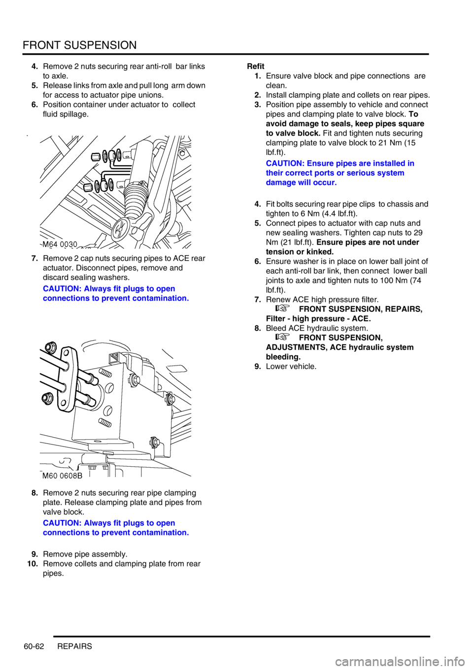
6.Position container under actuator to collect
fluid spillage.
7.Remove 2 cap nuts securing pipes to ACE rear
actuator. Disconnect pipes, remove and
discard sealing washers.
CAUTION: Always fit plugs to open
connections to prevent contamination.
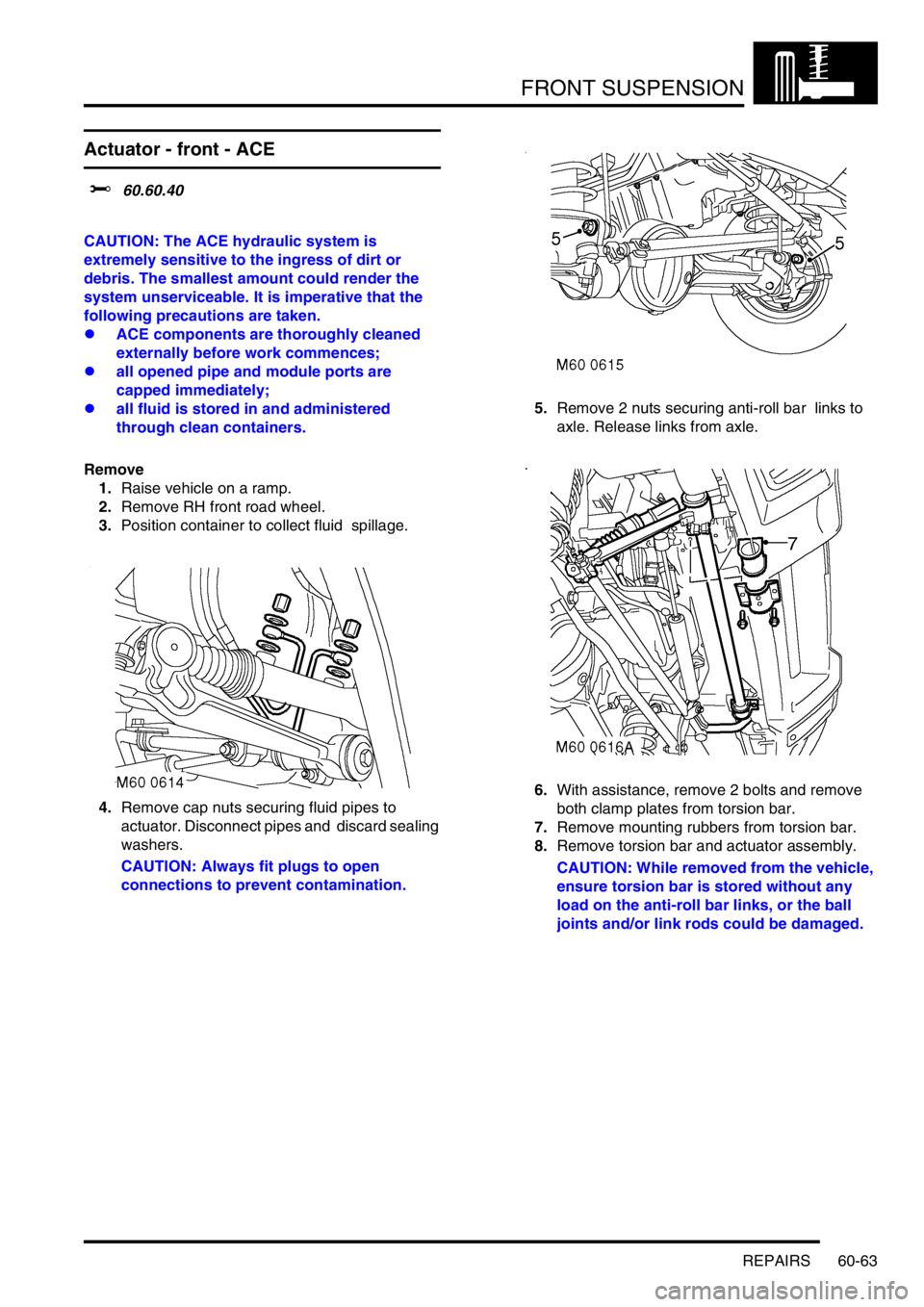
8.Remove 2 nuts securing rear pipe clamping
plate. Release clamping plate and pipes from
valve block.
CAUTION: Always fit plugs to open
connections to prevent contamination.
9.Remove pipe assembly.
10.Remove collets and clamping plate from rear
pipes. Refit
1.Ensure valve block and pipe connections are
clean.
2.Install clamping plate and collets on rear pipes.
3.Position pipe assembly to vehicle and connect
pipes and clamping plate to valve block. To
avoid damage to seals, keep pipes square
to valve block. Fit and tighten nuts securing
clamping plate to valve block to 21 Nm (15
lbf.ft).
CAUTION: Ensure pipes are installed in
their correct ports or serious system
damage will occur.
4.Fit bolts securing rear pipe clips to chassis and
tighten to 6 Nm (4.4 lbf.ft).
5.Connect pipes to actuator with cap nuts and
new sealing washers. Tighten cap nuts to 29
Nm (21 lbf.ft). Ensure pipes are not under
tension or kinked.
6.Ensure washer is in place on lower ball joint of
each anti-roll bar link, then connect lower ball
joints to axle and tighten nuts to 100 Nm (74
lbf.ft).
7.Renew ACE high pressure filter.
+ FRONT SUSPENSION, REPAIRS,
Filter - high pressure - ACE.
8.Bleed ACE hydraulic system.
+ FRONT SUSPENSION,
ADJUSTMENTS, ACE hydraulic system
bleeding.
9.Lower vehicle.
Page 1002 of 1672

FRONT SUSPENSION
REPAIRS 60-63
Actuator - front - ACE
$% 60.60.40
CAUTION: The ACE hydraulic system is
extremely sensitive to the ingress of dirt or
debris. The smallest amount could render the
system unserviceable. It is imperative that the
following precautions are taken.
lACE components are thoroughly cleaned
externally before work commences;
lall opened pipe and module ports are
capped immediately;
lall fluid is stored in and administered
through clean containers.
Remove
1.Raise vehicle on a ramp.
2.Remove RH front road wheel.
3.Position container to collect fluid spillage.
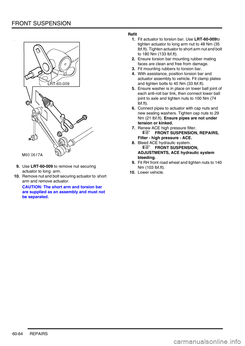
4.Remove cap nuts securing fluid pipes to
actuator. Disconnect pipes and discard sealing
washers.
CAUTION: Always fit plugs to open
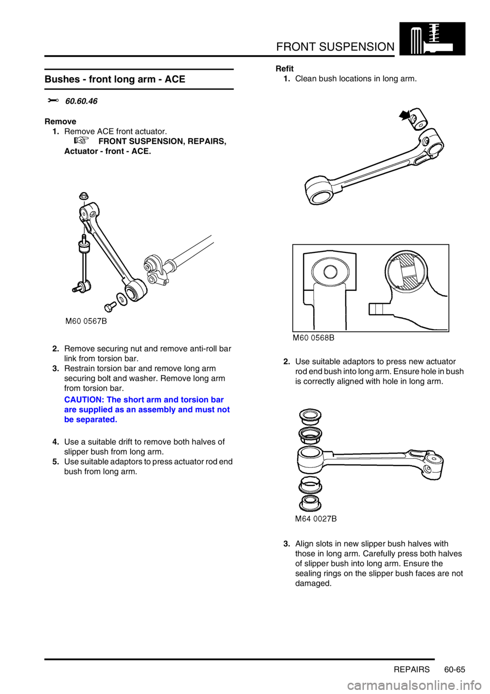
connections to prevent contamination.5.Remove 2 nuts securing anti-roll bar links to
axle. Release links from axle.
6.With assistance, remove 2 bolts and remove
both clamp plates from torsion bar.
7.Remove mounting rubbers from torsion bar.
8.Remove torsion bar and actuator assembly.
CAUTION: While removed from the vehicle,
ensure torsion bar is stored without any
load on the anti-roll bar links, or the ball
joints and/or link rods could be damaged.
Page 1003 of 1672

FRONT SUSPENSION
60-64 REPAIRS
9.Use LRT-60-009 to remove nut securing
actuator to long arm.
10.Remove nut and bolt securing actuator to short
arm and remove actuator.
CAUTION: The short arm and torsion bar
are supplied as an assembly and must not
be separated.Refit
1.Fit actuator to torsion bar. Use LRT-60-009to
tighten actuator to long arm nut to 48 Nm (35
lbf.ft). Tighten actuator to short arm nut and bolt
to 180 Nm (133 lbf.ft).
2.Ensure torsion bar mounting rubber mating
faces are clean and free from damage.
3.Fit mounting rubbers to torsion bar.
4.With assistance, position torsion bar and
actuator assembly to vehicle. Fit clamp plates
and tighten bolts to 45 Nm (33 lbf.ft).
5.Ensure washer is in place on lower ball joint of
each anti-roll bar link, then connect lower ball
joint to axle and tighten nuts to 100 Nm (74
lbf.ft).
6.Connect pipes to actuator with cap nuts and
new sealing washers. Tighten cap nuts to 29
Nm (21 lbf.ft). Ensure pipes are not under
tension or kinked.
7.Renew ACE high pressure filter.
+ FRONT SUSPENSION, REPAIRS,
Filter - high pressure - ACE.
8.Bleed ACE hydraulic system.
+ FRONT SUSPENSION,
ADJUSTMENTS, ACE hydraulic system
bleeding.
9.Fit RH front road wheel and tighten nuts to 140
Nm (103 lbf.ft).
10.Lower vehicle.
Page 1004 of 1672

FRONT SUSPENSION
REPAIRS 60-65
Bushes - front long arm - ACE
$% 60.60.46
Remove
1.Remove ACE front actuator.
+ FRONT SUSPENSION, REPAIRS,
Actuator - front - ACE.
2.Remove securing nut and remove anti-roll bar
link from torsion bar.
3.Restrain torsion bar and remove long arm
securing bolt and washer. Remove long arm
from torsion bar.
CAUTION: The short arm and torsion bar
are supplied as an assembly and must not
be separated.
4.Use a suitable drift to remove both halves of
slipper bush from long arm.
5.Use suitable adaptors to press actuator rod end
bush from long arm.Refit
1.Clean bush locations in long arm.
2.Use suitable adaptors to press new actuator
rod end bush into long arm. Ensure hole in bush
is correctly aligned with hole in long arm.
3.Align slots in new slipper bush halves with
those in long arm. Carefully press both halves
of slipper bush into long arm. Ensure the
sealing rings on the slipper bush faces are not
damaged.
Page 1011 of 1672

REAR SUSPENSION
64-6 DESCRIPTION AND OPERATION
Description
General
The rear suspension comprises two dampers, two radius arms, a Watts linkage and an anti-roll bar assembly. On
vehicles without Self Levelling Suspension (SLS) coil springs are used. On vehicles with SLS air springs are used.
The anti-roll bar is an essential part of the rear suspension. On vehicles without ACE, a conventional 'passive' anti-
roll bar is fitted. On vehicles fitted with the ACE system, a thicker diameter anti-roll bar, known as a torsion bar, is used
with an actuator at one end.
+ FRONT SUSPENSION, DESCRIPTION AND OPERATION, Description - ACE.
The hydraulic dampers and springs provide springing for each rear wheel. The long travel dampers, springs and
radius arms provide maximum axle articulation and wheel travel for off-road driving. The rear axle is controlled
longitudinally by two forged steel radius arms and transversely by a Watts linkage.
Radius arms
Each radius arm is manufactured from forged steel. Two bushes are pressed into the rear of the radius arm. The rear
of the radius arm is located between a fabricated bracket on the axle and secured through the bushes with two bolts
and nuts. A bush is pressed into the forward end of the radius arm which is located in a fabricated bracket on each
chassis longitudinal and secured through the bush with a bolt and nut. Each radius arm is similar in its construction
to the front radius arms. The rear radius arms are shorter than the front and have a lug for attachment of the SLS
height sensor (when fitted).
The radius arms prevent longitudinal movement of the rear axle and because of their length allow maximum axle
articulation. The stiffness of the bushes in each radius arm also contributes to the vehicle roll stiffness.
Each radius arm has a notch on its lower edge which provides location for the vehicle jack.
Dampers
Two conventional telescopic dampers are used to control body/axle movement. The upper damper mounting is fitted
with a bush which locates in a bracket on the chassis longitudinal. The damper is secured with a bolt which screws
into a captive nut on the bracket. The lower damper mounting is also fitted with a bush and locates in a fabricated
bracket attached to the rear axle. The lower mounting is secured with a bolt which screws into a captive nut on the
bracket. The upper and lower bushes are replaceable items.
Air springs (vehicles with SLS)
On vehicles with SLS fitted, air springs are fitted between the rear axle and the chassis. Each spring is located at its
base on a fabricated platform on the rear axle. The top of the spring locates in a fabricated bracket attached to the
outside of each chassis longitudinal.
The plastic base of the air spring has two lugs which locate in a slotted hole in the rear axle platform. The spring is
secured by rotating the spring through 90
°, locating the lug in the platform. The plastic top of the air spring has two
grooved pins which locate in holes in the bracket on the chassis. Two spring clips locate on the grooved pins and
retain the top of the spring in position.
Each air spring comprises a top plate assembly, an air bag and a base piston. The air bag is attached to the top plate
and the piston with a crimped ring. The air bag is made from a flexible rubber material which allows the bag to expand
with air pressure and deform under load. The top plate assembly comprises the plastic top plate with two bonded
grooved pins on its top face. In the centre of the top face is a female connector which allows for the attachment of the
air hose from the SLS compressor. The piston is made from plastic and is shaped to allow the air bag to roll over its
outer diameter. The base of the piston is recessed with a boss moulded in the centre. The boss has two lugs which
provide attachment to the axle platform.
Page 1012 of 1672

REAR SUSPENSION
DESCRIPTION AND OPERATION 64-7
Coil springs (vehicles without SLS)
On vehicles without SLS fitted, coil springs are fitted between the rear axle and the chassis in place of the SLS air
springs. Each spring is located at its base by the lower spring seat which is secured to a fabricated platform on the
rear axle with two bolts. The top of each spring is located in the upper spring seat. The upper spring seat comprises
a pressed metal plate with an outer coating of natural rubber bonded to the plate. The upper spring seat is retained
in position by the compression of the spring.
Coil Spring Specifications – Models up to 03 Model Year
The rear coil springs are of the variable rate type and are manufactured from silicon manganese 16.5 mm (0.65 in.)
diameter bar. Each spring has 9 coils and a free length of 385 mm (15.1 in.). The variable rate of the spring is achieved
by the active coils at one end being closer together. The rear coil spring is identified by a purple stripe painted on a
number of coils.
Coil Spring Specifications – Models From 03 Model Year
The introduction of the 03MY vehicle introduced a range of additional rear coil spring fitments. These were introduced
as a package to optimise vehicle trim heights.
The coil springs are manufactured from silicon manganese 16.35 mm (0.64 in.) diameter bar for springs on five seater
models and 16.57 mm (0.65 in.) diameter bar on seven seater models. The following spring data table shows the
colour codes, number of coils and spring free length.
Spring Data
The following table shows spring fitment applicability.
Spring Fitment Applicability
Watts linkage
A Watts linkage is used to ensure that the rear axle remains centrally located. The Watts linkage comprises two
transverse links and a pivot housing. The transverse links and pivot housing allow the rear axle to move vertically
without any transverse movement.
The transverse links are made from fabricated and welded steel. Each transverse link has a bush press fitted into a
housing at one end. The opposite end has a forked bracket with two cross holes.
The pivot housing is made from cast iron. Three bushes are press fitted in the housing, one in the centre and one at
each end.
Colour Code Total No. of Coils Free Length Model
Brown/Orange 8.73 384.7 mm (15.14 in) 5 Seat
Grey/Orange 8.73 392 mm (15.43 in) 5 Seat
Yellow/Grey 8.73 376.6 mm (14.82 in) 5 Seat
Pink/Grey 8.73 400.3 mm (15.75 in) 5 Seat
Blue/Grey 9.10 387.8 mm (15.26 in) 7 Seat
Green/Grey 9.10 395.2 mm (15.55 in) 7 Seat
White/Grey 9.10 380.6 mm (14.98 in) 7 Seat
Left Hand Drive Right Hand Drive
Both Sides RH Side LH Side
Brown/Orange Grey/Orange Yellow/Grey
Grey Orange Pink/Grey Brown/Orange
Blue/Grey Green/Grey White/Grey