Page 1360 of 1672

HEATING AND VENTILATION
REPAIRS 80-19
Servo - air distribution control
$% 80.10.30
Remove
1.Disconnect battery earth lead.
2. RHD models: Remove heater assembly.
+ HEATING AND VENTILATION,
REPAIRS, Heater assembly - models with
air conditioning.
3. LHD models: Remove heater motor assembly.
+ HEATING AND VENTILATION,
REPAIRS, Blower assembly.
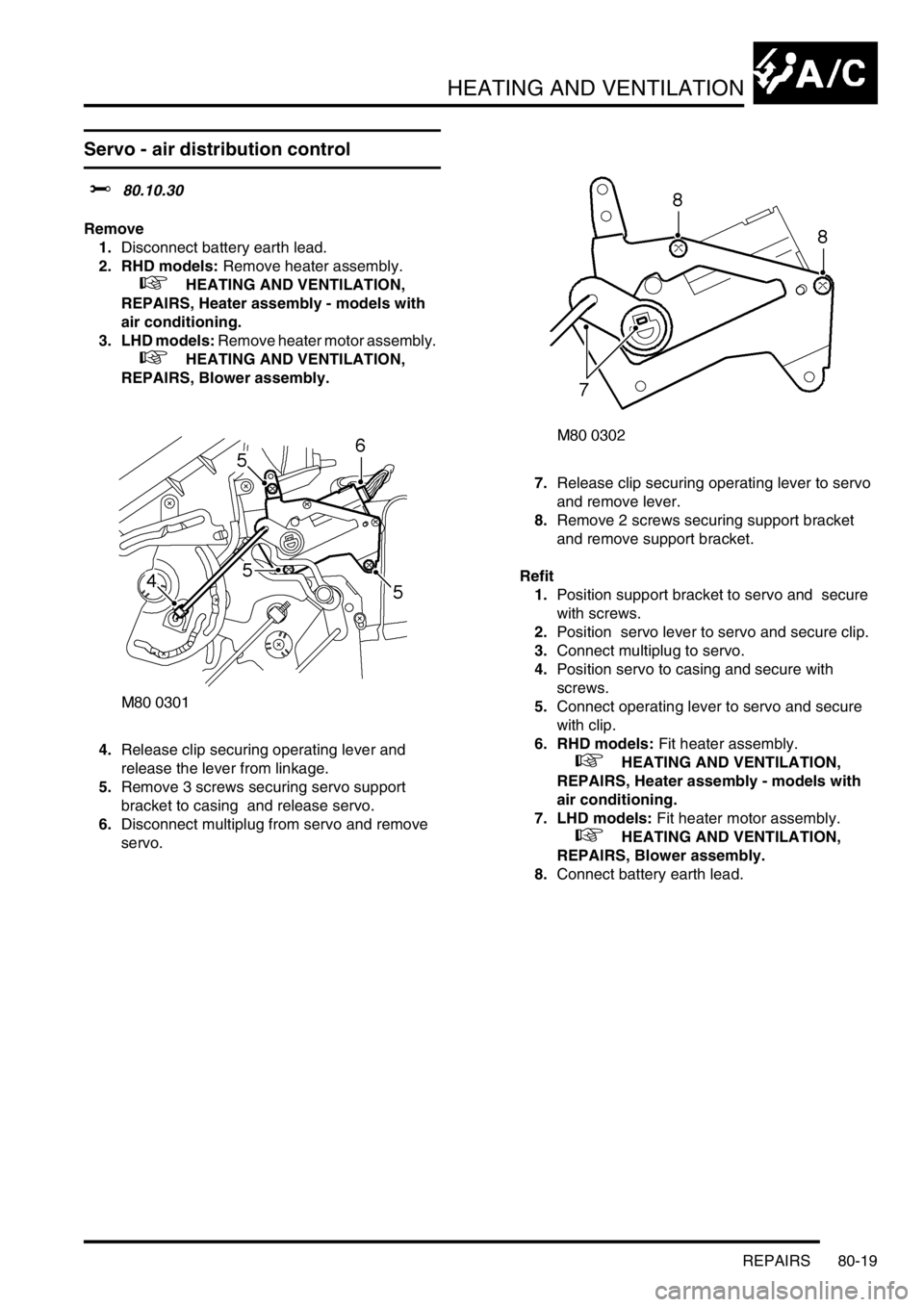
4.Release clip securing operating lever and
release the lever from linkage.
5.Remove 3 screws securing servo support
bracket to casing and release servo.
6.Disconnect multiplug from servo and remove
servo. 7.Release clip securing operating lever to servo
and remove lever.
8.Remove 2 screws securing support bracket
and remove support bracket.
Refit
1.Position support bracket to servo and secure
with screws.
2.Position servo lever to servo and secure clip.
3.Connect multiplug to servo.
4.Position servo to casing and secure with
screws.
5.Connect operating lever to servo and secure
with clip.
6. RHD models: Fit heater assembly.
+ HEATING AND VENTILATION,
REPAIRS, Heater assembly - models with
air conditioning.
7. LHD models: Fit heater motor assembly.
+ HEATING AND VENTILATION,
REPAIRS, Blower assembly.
8.Connect battery earth lead.
Page 1361 of 1672

HEATING AND VENTILATION
80-20REPAIRS
Servo - air temperature control
$% 80.10.42
Remove
1.Disconnect battery earth lead.
2. Driver side: Remove heater assembly.
+ HEATING AND VENTILATION,
REPAIRS, Heater assembly - models with
air conditioning.
3. Passenger side: Remove blower assembly.
+ HEATING AND VENTILATION,
REPAIRS, Blower assembly.
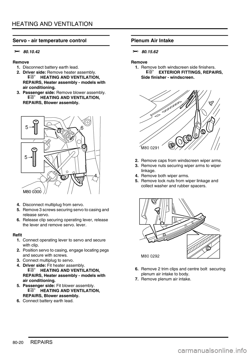
4.Disconnect multiplug from servo.
5.Remove 3 screws securing servo to casing and
release servo.
6.Release clip securing operating lever, release
the lever and remove servo. lever.
Refit
1.Connect operating lever to servo and secure
with clip.
2.Position servo to casing, engage locating pegs
and secure with screws.
3.Connect multiplug to servo.
4. Driver side: Fit heater assembly.
+ HEATING AND VENTILATION,
REPAIRS, Heater assembly - models with
air conditioning.
5. Passenger side: Fit blower assembly.
+ HEATING AND VENTILATION,
REPAIRS, Blower assembly.
6.Connect battery earth lead.
Plenum Air Intake
$% 80.15.62
Remove
1.Remove both windscreen side finishers.
+ EXTERIOR FITTINGS, REPAIRS,
Side finisher - windscreen.
2.Remove caps from windscreen wiper arms.
3.Remove nuts securing wiper arms to wiper
linkage.
4.Remove both wiper arms.
5.Remove lock nuts from wiper linkage and
collect washer and rubber spacers.
6.Remove 2 trim clips and centre bolt securing
plenum air intake to body.
7.Remove plenum air intake.
Page 1362 of 1672
HEATING AND VENTILATION
REPAIRS 80-21
Refit
1.Fit plenum air intake.
2.Fit trim clips and centre bolt securing plenum
air intake to body.
3.Fit rubber spacers and washers to wiper
linkage.
4.Fit locknuts to wiper linkage and tighten to 7
Nm (5.2 lbf.ft).
5.Fit wiper arms to wiper linkage.
6.Fit nuts securing wiper arms to wiper linkage
and tighten to 15 Nm (11 lbf.ft).
7.Fit caps to wiper arms.
8.Fit both windscreen side finishers.
+ EXTERIOR FITTINGS, REPAIRS,
Side finisher - windscreen.
Heater assembly - models without air
conditioning
$% 80.20.01.99
Remove
1.Drain cooling system.
l
+ COOLING SYSTEM - Td5,
ADJUSTMENTS, Drain and refill.
l
+ COOLING SYSTEM - V8,
ADJUSTMENTS, Drain and refill.
2. Diesel models: Remove 3 bolts and remove
engine cover.
3.Release clips and disconnect coolant hoses
from heater pipes.
CAUTION: Always fit plugs to open
connections to prevent contamination.
4.Remove facia assembly.
+ INTERIOR TRIM COMPONENTS,
REPAIRS, Fascia.
Page 1364 of 1672

HEATING AND VENTILATION
REPAIRS 80-23
14.Remove 2 screws securing matrix pipe bracket
to heater casing.
15.Remove screw securing pipe clamp to heater
casing and remove clamp.
16.Carefully remove matrix from heater.
Refit
1.Fit matrix into heater casing.
2.Fit screws securing pipe bracket to heater
casing.
3.Fit pipe clamp and secure with screw.
4.Fit heater ducts and secure with screws.
5.Position heater assembly to vehicle, ensure
heater coolant pipe grommet is correctly
located in bulkhead and secure with nuts and
bolt.
6.Fit radio coaxial cable behind heater pipes.
7.Fit console bracket and secure with screws.
8.Connect drain tubes to base of heater.
9.Fit blower unit to heater and secure to body
with nuts and bolt.
10.Connect harness multiplug to blower motor.
11.Fit facia assembly
+ INTERIOR TRIM COMPONENTS,
REPAIRS, Fascia.
12.Connect heater hoses and secure with clips.
13. Diesel models: Fit engine cover and secure
with bolts.
14.Refill cooling system
l
+ COOLING SYSTEM - Td5,
ADJUSTMENTS, Drain and refill.
l
+ COOLING SYSTEM - V8,
ADJUSTMENTS, Drain and refill.
Heater assembly - models with air
conditioning
$% 80.20.01.98
Remove
1.Drain cooling system.
l
+ COOLING SYSTEM - V8,
ADJUSTMENTS, Drain and refill.
l
+ COOLING SYSTEM - Td5,
ADJUSTMENTS, Drain and refill.
2.Evacuate air conditioning system.
+ AIR CONDITIONING, REFRIGERANT
RECOVERY, RECYCLING AND
RECHARGING, Refrigerant recovery,
recycling and recharging.
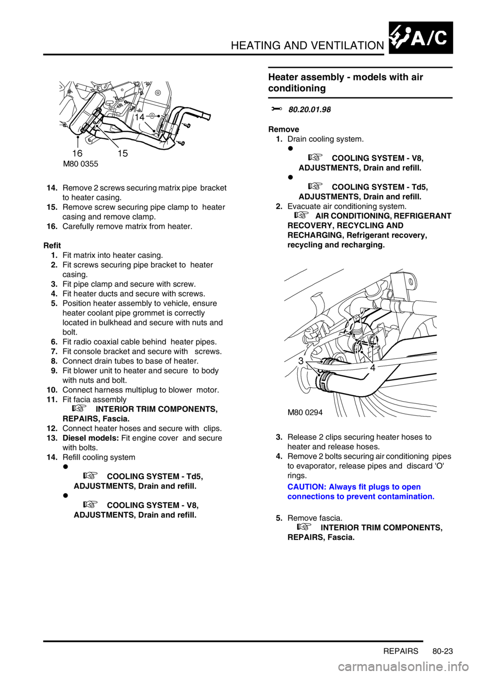
3.Release 2 clips securing heater hoses to
heater and release hoses.
4.Remove 2 bolts securing air conditioning pipes
to evaporator, release pipes and discard 'O'
rings.
CAUTION: Always fit plugs to open
connections to prevent contamination.
5.Remove fascia.
+ INTERIOR TRIM COMPONENTS,
REPAIRS, Fascia.
Page 1366 of 1672

HEATING AND VENTILATION
REPAIRS 80-25
11.Disconnect both evaporator drain hoses.
12.Remove front heater ducting.
13.Remove 4 nuts and bolt securing heater
assembly, release heater assembly from
bulkhead grommet and remove from vehicle.
Refit
1.Position heater assembly to bulkhead, locate
heater in bulkhead grommet.
2.Fit nuts and bolt securing heater and tighten to
16 Nm (12 lbf.ft).
3.Position RH fascia support bracket, fit and
tighten nuts.
4.Fit front heater ducting.
5.Position centre console support bracket, fit and
tighten screws.
6.Connect evaporator drain hoses.
7.Position heater motor to heater casing, fit nuts
and bolt and tighten to 19 Nm (14 lbf.ft).
8.Connect multiplug heater motor.
9.Position rear heater ducting and secure with
screws.
10.Fit fascia.
+ INTERIOR TRIM COMPONENTS,
REPAIRS, Fascia.
11.Using new 'O' rings, position air conditioning
pipes to evaporator fit bolts and tighten to 5 Nm
(3.7 lbf.ft).
12.Position heater hoses and secure hose clips.
13.Recharge air conditioning system.
+ AIR CONDITIONING, REFRIGERANT
RECOVERY, RECYCLING AND
RECHARGING, Refrigerant recovery,
recycling and recharging.
14.Refill cooling system.
l
+ COOLING SYSTEM - V8,
ADJUSTMENTS, Drain and refill.
l
+ COOLING SYSTEM - Td5,
ADJUSTMENTS, Drain and refill.
Blower assembly
$% 80.20.12
Remove
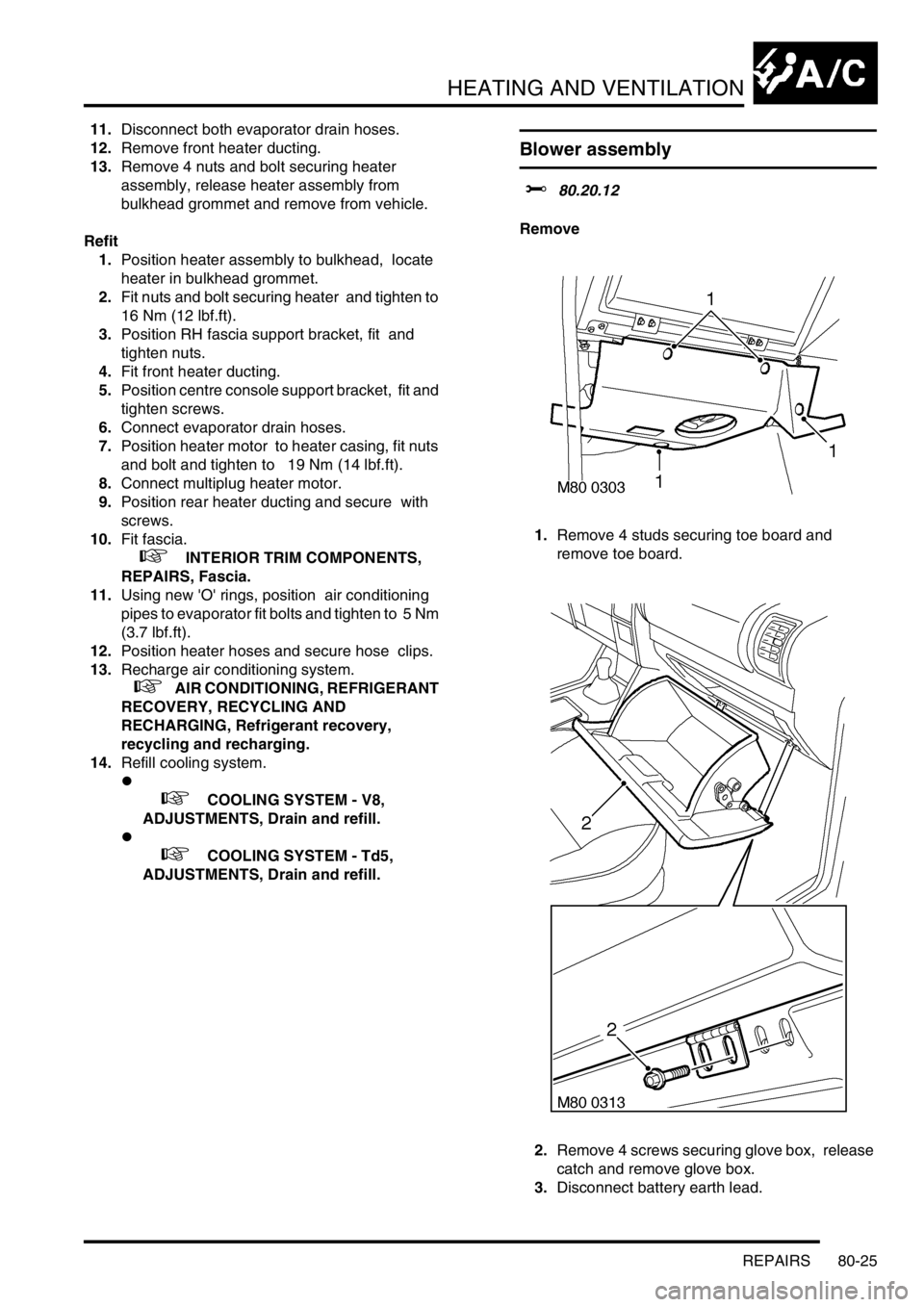
1.Remove 4 studs securing toe board and
remove toe board.
2.Remove 4 screws securing glove box, release
catch and remove glove box.
3.Disconnect battery earth lead.
Page 1369 of 1672
HEATING AND VENTILATION
80-28REPAIRS
3.Disconnect multiplug from resistor.
4.Remove screws securing resistor, release and
remove resistor.
Refit
1.Position resistor and secure with screw.
2.Connect multiplug to resistor.
3.Position glove box, fit and tighten screws.
4.Position toe board and secure with studs.
Heater matrix
$% 80.20.29
Remove
1.Remove heater assembly.
+ HEATING AND VENTILATION,
REPAIRS, Heater assembly - models with
air conditioning.
2.Remove 2 screws securing coolant pipe
saddles and remove saddles.
3.Loosen screws securing coolant pipes to
matrix, release clamps and remove coolant
pipes.
4.Remove and discard 'O' rings.
5.Remove heater matrix.
Refit
1.Position heater matrix, using new 'O' rings fit
coolant pipes and align clamps.
2.Fit saddle clamps and secure with screws
3.Tighten coolant pipe clamp screws.
4.Fit heater assembly.
+ HEATING AND VENTILATION,
REPAIRS, Heater assembly - models with
air conditioning.
Page 1374 of 1672
AIR CONDITIONING
DESCRIPTION AND OPERATION 82-1
AIR CONDITIONING DESCRIPTION AND OPERAT ION
A/C refrigerant system component
layout
Diesel installation shown, V8 similar
1Evaporator and thermostatic expansion valve
2High pressure servicing connection
3To rear A/C system (where fitted)
4Low pressure servicing connection
5Refrigerant lines
6Receiver drier
7Condenser
8Compressor
Page 1375 of 1672
AIR CONDITIONING
82-2DESCRIPTION AND OPERATION
A/C control system component layout
RH drive shown, LH drive similar
1Air temperature control ECU
2Heater coolant temperature sensor
3Evaporator temperature sensor
4Dual pressure switch
5Ambient temperature sensor
6Sunlight sensor
7In-car temperature sensor