2002 LAND ROVER DISCOVERY AUX
[x] Cancel search: AUXPage 901 of 1672

STEERING
57-14 DESCRIPTION AND OPERATION
The PAS pump is located on the auxiliary housing, two bolts go through the PAS pump, mounting bracket and into
the auxiliary housing. One bolt also attaches the mounting bracket to the PAS pump, two bolts secure the mounting
bracket to the auxiliary housing. An inlet adaptor pipe with a seal is secured to the bottom of the pump with two bolts.
A drive pulley is attached to the pump drive shaft with three bolts, and is belt driven at a ratio of 1.35 crankshaft
revolutions to 1 of the drive pulley. A coupling on the rear of the PAS pump rotates the water pump impeller located
in the auxiliary housing. Fluid is supplied to the PAS pump inlet from the reservoir through a flexible hose at low
(suction) pressure. Fluid at high pressure from the PAS pump outlet is supplied to the rotary control valve on the
steering box.
The PAS pump is a roller vane type and has an internal pressure regulator and flow control valve. The roller vanes
can move in slots in the pumps rotor and are moved outwards by centrifugal force as the pump rotates. The pump
rotor rotates in the pump housing, the internal shape of the housing forms a 'cam' shape. Due to the 'cam' shape the
volume of the housing decreases between the inlet and outlet ports.
As the pump rotor rotates towards the pump inlet the volume between the roller vanes and the pump housing
increases, this action causes a depression in the chamber between the pump roller vanes and the housing. As the
rotation continues the chamber is opened to the pump inlet, and the depression in the chamber causes fluid to be
drawn in. The roller vanes continue past the inlet port, closing off the inlet port and trapping the fluid in the chamber
between the rollers and the pump housing.
The internal 'cam' shape of the pump housing causes the rollers to move closer together as the pump rotor rotates
towards the outlet port. The reduced volume of the chamber between the roller vanes causes the fluid to become
pressurised. When the chamber is opened to the outlet port of the pump the fluid escapes at high pressure. The roller
vanes continue turning and go past the outlet port, closing off the chamber between the two roller vanes.
As rotation continues the inlet sequence begins again. The inlet and pressurisation/outlet sequences continue as the
pump rotates, and is repeated between each two roller vanes. The pump is a positive displacement type and the
potential pump output increases with engine (drive pulley) speed. The pressure relief and flow control valve regulates
flow/pressure by diverting fluid back to the pump inlet through internal recirculation passages in the pump body.
Steering damper
The steering damper is located behind and just below the first cross member of the chassis. The ends of the steering
damper have steel 'eyes' welded on, rubber bushes are installed in each 'eye'. The steering damper is attached
between brackets on the chassis rail and the drag link. Each end of the steering damper is secured by a bolt and
locknut. The hydraulic damper absorbs shocks in the steering, caused by road wheel deflections when operating on
rough terrain.
Page 926 of 1672

STEERING
REPAIRS 57-39
Refit
1.Clean seal recess, output shaft, end cover and
mating face.
2.Lubricate new end cover 'O' ring with clean
PAS fluid. Fit 'O' ring to end cover.
3.Position output shaft, fit bolts and tighten to 88
Nm (65 lbf.ft).
4.Tighten rack adjuster one turn, align marks and
secure with Allen screw.
5.Lubricate new output shaft seal with clean PAS
fluid.
6.Fit seal using LRT-57-504.
7.Fit spacer, circlip and seal shield.
8.Clean drop arm and steering box splines.
9.Ensure steering box is in the central position.
Align and fit drop arm to output shaft and
secure with new lock washer and nut. Tighten
nut to 240 Nm (177 lbf.ft).
10.Secure lock washer to drop arm nut.
11.Fit steering box.
lFor V8 models:
+ STEERING, REPAIRS, Power
steering box - V8.
lFor LHD diesel models:
+ STEERING, REPAIRS, Power
steering box - LHD - diesel.
lFor RHD diesel models:
+ STEERING, REPAIRS, Steering
box - RHD - diesel.
Pump - power steering - V8
$% 57.20.14
Remove
1.Remove auxiliary drive belt.
+ CHARGING AND STARTING,
REPAIRS, Belt - auxiliary drive.
2.Remove cable tie securing harness to air intake
hose.
3.Loosen 3 clips securing air intake hose, release
and remove hose.
Note: Pre 03 MY air intake hose illustrated.
4. Models with ACE: Remove 3 bolts securing
ACE pump, release pump and position aside.
Page 927 of 1672

STEERING
57-40 REPAIRS
5. Models with A/C: Disconnect A/C compressor
multiplug. Remove 4 bolts securing A/C
compressor, release compressor and position
aside.
6.Remove 3 bolts securing PAS pump pulley and
remove pulley.
7.Position tray to catch spillage, release PAS
pump pressure pipe.
8.Remove clip and release PAS pump inlet hose.
CAUTION: Always fit plugs to open
connections to prevent contamination.9.Remove jockey pulley.
10.Remove bolt securing oil cooling pipe bracket
and release bracket from housing.
11.Remove two bolts securing PAS pump.
12.Remove 4 bolts and one nut securing auxiliary
housing. Pull housing forward and release
PAS pump. Remove PAS pump.
Page 928 of 1672

STEERING
REPAIRS 57-41
Refit
1.Position PAS pump to auxiliary housing and
locate housing to engine. Fit and tighten
auxiliary housing bolts to 40 Nm (30 lbf.ft).
2.Tighten auxiliary housing nut to 10 Nm (7 lbf.ft).
3.Fit bolts securing PAS pump and tighten to 22
Nm (16 lbf.ft).
4.Position PAS pump pipe bracket, fit and tighten
bolt to 22 Nm (16 lbf.ft).
5.Fit and tighten PAS pump pressure pipe.
6.Fit PAS pump inlet hose and secure with clip.
7.Position jockey pulley and tighten bolt to 50 Nm
(37 lbf.ft).
8.Clean PAS pump pulley mating faces.
9.Position PAS pump pulley, fit bolts and tighten
to 22 Nm (16 lbf.ft).
10. Models with ACE: Clean ACE pump dowels
and dowel holes. Position ACE pump, fit bolts
and tighten to 25 Nm (18 lbf.ft).
11. Models with A/C: Clean A/C compressor
dowels and dowel holes. Position A/C
compressor, fit bolts and tighten to 22 Nm (16
lbf.ft).
12.Position air intake hose and secure with clips.
13.Secure harness to air intake hose with new
cable tie.
14.Fit auxiliary drive belt.
+ CHARGING AND STARTING,
REPAIRS, Belt - auxiliary drive..
15.Bleed PAS system.
+ STEERING, ADJUSTMENTS,
Hydraulic system - bleed.
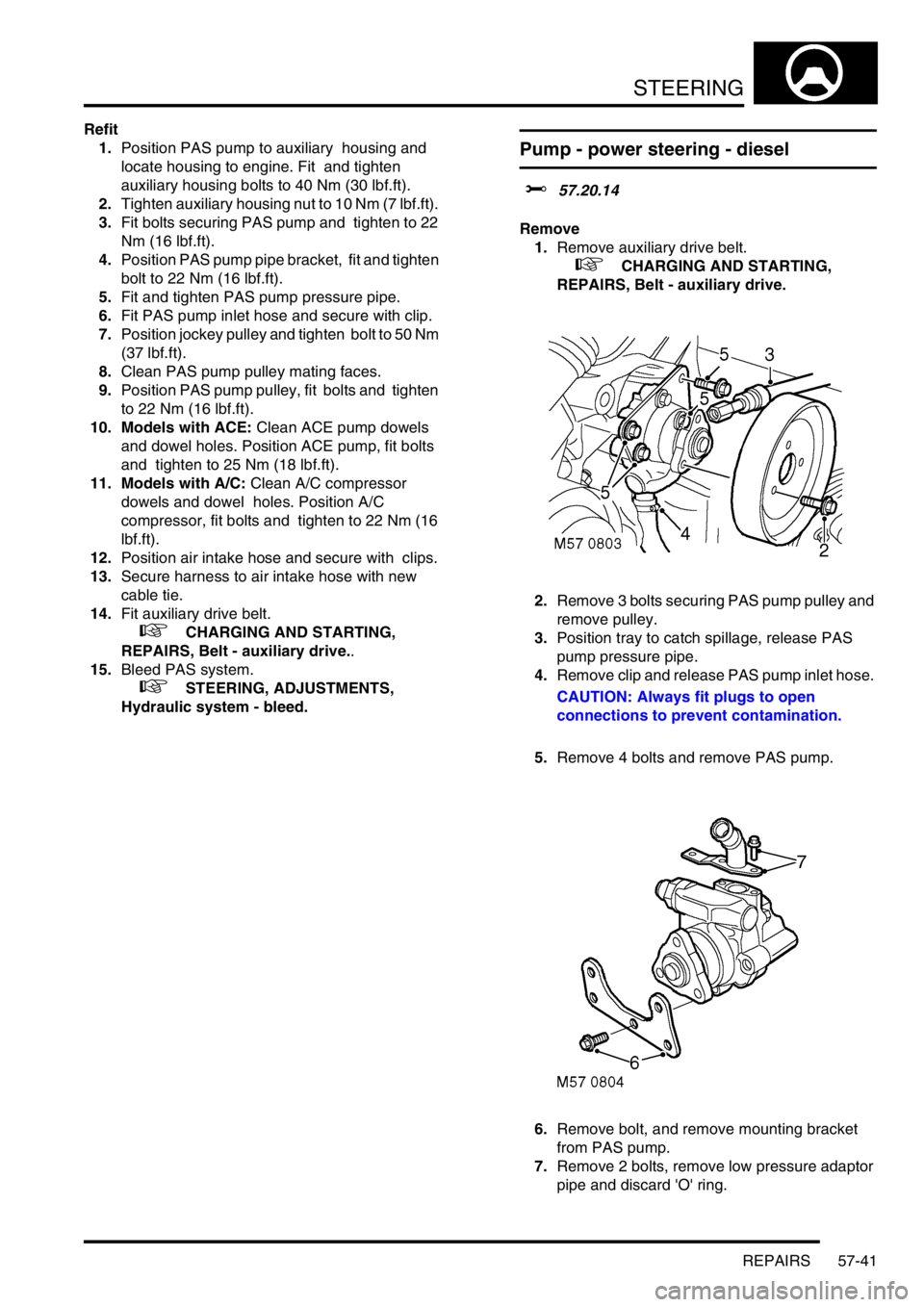
Pump - power steering - diesel
$% 57.20.14
Remove
1.Remove auxiliary drive belt.
+ CHARGING AND STARTING,
REPAIRS, Belt - auxiliary drive.
2.Remove 3 bolts securing PAS pump pulley and
remove pulley.
3.Position tray to catch spillage, release PAS
pump pressure pipe.
4.Remove clip and release PAS pump inlet hose.
CAUTION: Always fit plugs to open
connections to prevent contamination.
5.Remove 4 bolts and remove PAS pump.
6.Remove bolt, and remove mounting bracket
from PAS pump.
7.Remove 2 bolts, remove low pressure adaptor
pipe and discard 'O' ring.
Page 929 of 1672

STEERING
57-42 REPAIRS
Refit
1.Clean PAS pump and adaptor pipe.
2.Fit new 'O' ring to adaptor pipe, fit pipe and
tighten bolts to 10 Nm (7 lbf.ft).
3.Position mounting bracket to PAS pump, fit but
do not tighten bolt.
4.Position PAS pump and align pump drive to
coolant pump. Fit and tighten bolts to 25 Nm
(18 lbf.ft).
5.Tighten mounting plate bolt to 25 Nm (18 lbf.ft).
6.Clean PAS pump and pipe union.
7.Fit and tighten PAS pump pressure pipe to 20
Nm (15 lbf.ft).
8.Fit PAS pump inlet hose and secure with clip.
9.Clean PAS pump and pulley mating faces.
10.Position PAS pump pulley, fit and tighten bolts
to 10 Nm (7 lbf.ft).
11.Fit auxiliary drive belt.
+ CHARGING AND STARTING,
REPAIRS, Belt - auxiliary drive.
12.Bleed power steering system.
+ STEERING, ADJUSTMENTS,
Hydraulic system - bleed.
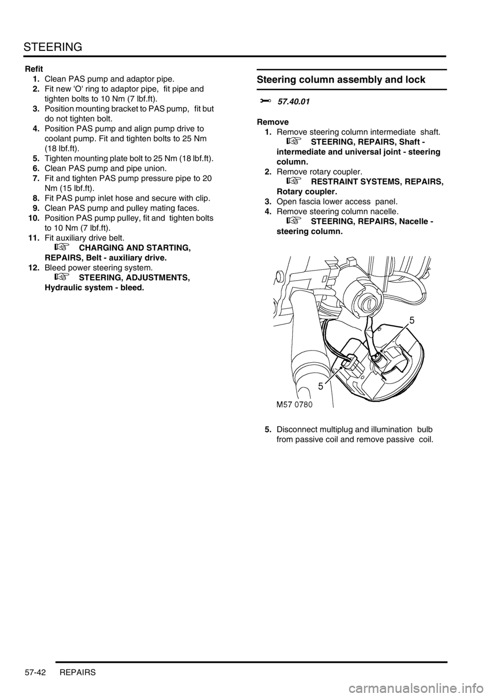
Steering column assembly and lock
$% 57.40.01
Remove
1.Remove steering column intermediate shaft.
+ STEERING, REPAIRS, Shaft -
intermediate and universal joint - steering
column.
2.Remove rotary coupler.
+ RESTRAINT SYSTEMS, REPAIRS,
Rotary coupler.
3.Open fascia lower access panel.
4.Remove steering column nacelle.
+ STEERING, REPAIRS, Nacelle -
steering column.
5.Disconnect multiplug and illumination bulb
from passive coil and remove passive coil.
Page 953 of 1672

FRONT SUSPENSION
60-14 DESCRIPTION AND OPERATION
Hydraulic pump
1Outlet port
2Cap
3Piston spring
4Piston
5Inlet port
6Cylinder housing
7Shaft8Cam
9Inlet housing
10Spring
11Discharge valve
12Housing
13Pulley attachment flange
The hydraulic pump is attached to a bracket on the left hand side of the engine and is driven at crankshaft speed by
the auxiliary drive belt. The pump is of the radial piston type which delivers fluid at high pressure.
The radial piston pump has six pistons located in bores in a cylinder housing. A central shaft, which is driven by a
pulley and the auxiliary drive belt, has a cam which operates the pistons as it rotates.
As the cam lobe reaches each piston, the piston is pushed outward, moving the fluid above the piston. The pressure
created by the fluid flow from the bore opens a spring loaded discharge valve and allows the fluid to flow to the pump
outlet port. When the piston reaches its full stroke, the flow reduces and the discharge valve closes under spring
pressure.
Page 981 of 1672

FRONT SUSPENSION
60-42 REPAIRS
Accelerometer - ACE - lower
$% 60.60.03
CAUTION: The accelerometer is an extremely
delicate component and can easily be rendered
unserviceable. Never use an accelerometer
which has been dropped or subjected to
mistreatment of any type.
Remove
1.Raise vehicle on a ramp.
2.Disconnect multiplug from accelerometer.
3.Use LRT-60-014A to release clip and remove
accelerometer.
Refit
1.Use LRT-60-014A, fit accelerometer fully into
clip.
2.Connect accelerometer multiplug.
3.Lower vehicle.
4.If a replacement accelerometer has been fitted,
use TestBook to calibrate ACE system.
Pump - ACE - V8
$% 60.60.10
CAUTION: The ACE hydraulic system is
extremely sensitive to the ingress of dirt or
debris. The smallest amount could render the
system unserviceable. It is imperative that the
following precautions are taken.
lACE components are thoroughly cleaned
externally before work commences;
lall opened pipe and module ports are
capped immediately;
lall fluid is stored in and administered
through clean containers.
Remove
1.Remove auxiliary drive belt.
+ CHARGING AND STARTING,
REPAIRS, Belt - auxiliary drive.
2.Loosen 3 clips securing air intake hose.
Release air intake hose and position aside.
Note: Pre 03 MY air intake hose illustrated.
Page 982 of 1672

FRONT SUSPENSION
REPAIRS 60-43
3.Position container to catch spillage.
4.Release clip on pump suction hose and
disconnect hose.
CAUTION: Always fit plugs to open
connections to prevent contamination.
5.Remove banjo bolt and disconnect pressure
pipe from ACE pump. Discard sealing washers.
CAUTION: Always fit plugs to open
connections to prevent contamination.
6.Remove 3 bolts securing ACE pump to
mounting and remove ACE pump.
7.Restrain pulley, remove 3 securing bolts and
remove pulley from ACE pump. Refit
1.Clean mating faces of pulley and ACE pump.
2.Position pulley to ACE pump and fit bolts.
Restrain pulley and tighten bolts to 25 Nm (18
lbf.ft).
3.Clean mating faces of ACE pump and
mounting.
4.Connect suction hose to ACE pump and secure
with clip.
5.Ensure there is sufficient fluid in ACE/PAS
reservoir to prime ACE pump.
6.Position ACE pump below level of ACE/PAS
reservoir, with suction hose uppermost, and
allow fluid from ACE/PAS reservoir to
completely fill ACE pump.
7.Position ACE pump to mounting, fit bolts and
tighten to 25 Nm (18 lbf.ft).
8.Rotate ACE pump clockwise (viewed from
pulley end) until a steady flow of fluid runs from
outlet port.
9.Connect pressure pipe to ACE pump with banjo
bolt and new sealing washers. Tighten banjo
bolt to 28 Nm (21 lbf.ft).
10.Position air intake hose and secure clips.
11.Fit auxiliary drive belt.
+ CHARGING AND STARTING,
REPAIRS, Belt - auxiliary drive.
12.Renew ACE high pressure filter.
+ FRONT SUSPENSION, REPAIRS,
Filter - high pressure - ACE.