2002 LAND ROVER DISCOVERY weight
[x] Cancel search: weightPage 1099 of 1672
RESTRAINT SYSTEMS
75-4 DESCRIPTION AND OPERATION
Driver airbag module
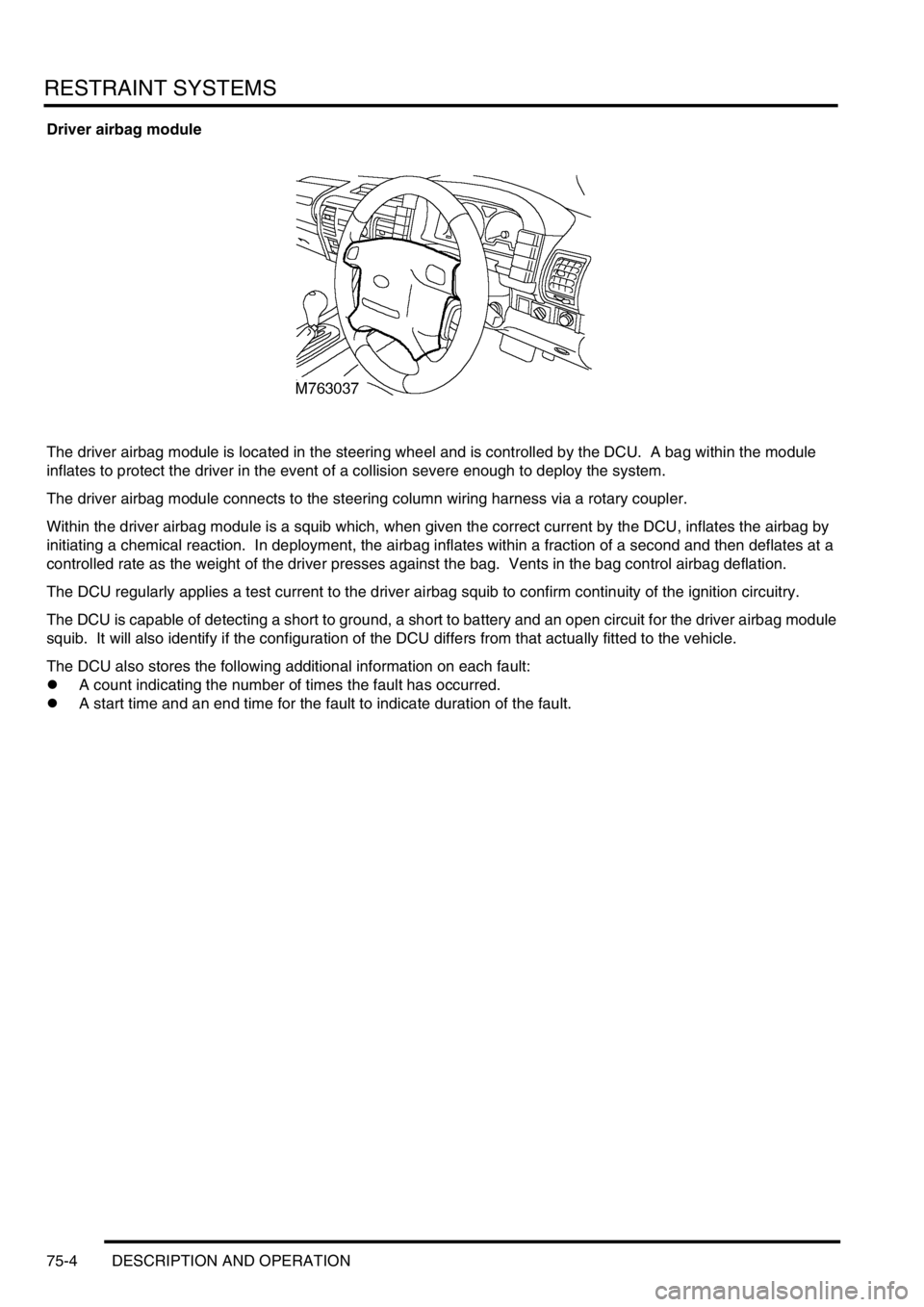
The driver airbag module is located in the steering wheel and is controlled by the DCU. A bag within the module
inflates to protect the driver in the event of a collision severe enough to deploy the system.
The driver airbag module connects to the steering column wiring harness via a rotary coupler.
Within the driver airbag module is a squib which, when given the correct current by the DCU, inflates the airbag by
initiating a chemical reaction. In deployment, the airbag inflates within a fraction of a second and then deflates at a
controlled rate as the weight of the driver presses against the bag. Vents in the bag control airbag deflation.
The DCU regularly applies a test current to the driver airbag squib to confirm continuity of the ignition circuitry.
The DCU is capable of detecting a short to ground, a short to battery and an open circuit for the driver airbag module
squib. It will also identify if the configuration of the DCU differs from that actually fitted to the vehicle.
The DCU also stores the following additional information on each fault:
lA count indicating the number of times the fault has occurred.
lA start time and an end time for the fault to indicate duration of the fault.
Page 1100 of 1672
RESTRAINT SYSTEMS
DESCRIPTION AND OPERATION 75-5
Passenger airbag module
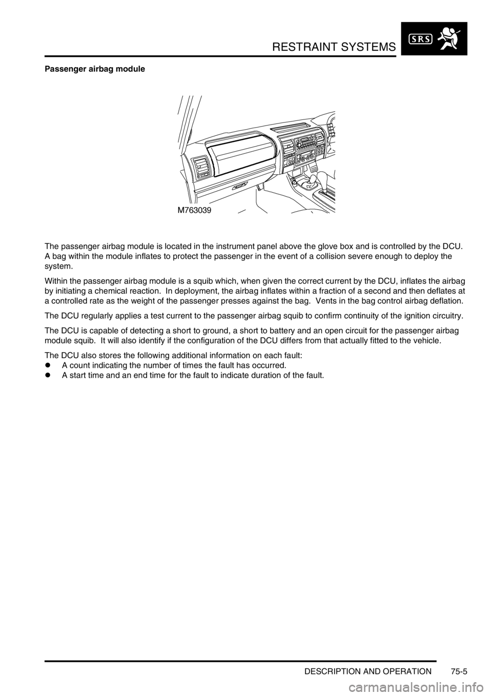
The passenger airbag module is located in the instrument panel above the glove box and is controlled by the DCU.
A bag within the module inflates to protect the passenger in the event of a collision severe enough to deploy the
system.
Within the passenger airbag module is a squib which, when given the correct current by the DCU, inflates the airbag
by initiating a chemical reaction. In deployment, the airbag inflates within a fraction of a second and then deflates at
a controlled rate as the weight of the passenger presses against the bag. Vents in the bag control airbag deflation.
The DCU regularly applies a test current to the passenger airbag squib to confirm continuity of the ignition circuitry.
The DCU is capable of detecting a short to ground, a short to battery and an open circuit for the passenger airbag
module squib. It will also identify if the configuration of the DCU differs from that actually fitted to the vehicle.
The DCU also stores the following additional information on each fault:
lA count indicating the number of times the fault has occurred.
lA start time and an end time for the fault to indicate duration of the fault.
Page 1264 of 1672
PANEL REPAIRS
PROCEDURES 77-2-15
PROCEDURES
Panel replacement procedure
This procedure is designed to explain the basic panel
removal and replacement method. The main criterion
in removal and replacement of body panels is that
the original standard is maintained as far as possible.
While individual repairs will differ in detail, this
procedure has been devised placing emphasis on
ease of repair and the elimination of unnecessary
work.
Body panels are being increasingly manufactured in
high strength steels to meet design requirements for
safety and weight saving. As panels in high strength
steels cannot be visually identified, and as they are
more sensitive to excess heat than panels
manufactured from low carbon steel, it is advisable
that the following procedure be observed at all times.
Remove panel
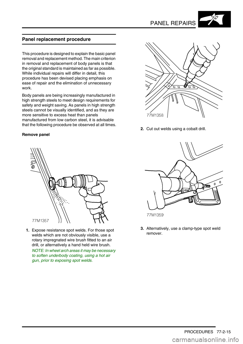
1.Expose resistance spot welds. For those spot
welds which are not obviously visible, use a
rotary impregnated wire brush fitted to an air
drill, or alternatively a hand held wire brush.
NOTE: In wheel arch areas it may be necessary
to soften underbody coating, using a hot air
gun, prior to exposing spot welds.2.Cut out welds using a cobalt drill.
3.Alternatively, use a clamp-type spot weld
remover.
Page 1311 of 1672

BODY SEALING MATERIALS
77-3-4 MATERIALS AND APPLICATIONS
Application equipment
Manufacturers and suppliers
Suitable application equipment is available from the following manufacturers and suppliers:
3M
Automotive Trades Group
3M UK Plc
3M House
PO Box 1
Market Place
Bracknell
Berks
RG 12 1JU
( (01344) 858611
Cooper Pegler
Burgess Hill
Sussex
RH15 9LA
( (014 446) 42526
SATA Spray Equipment
Minden Industrial Ltd
16 Greyfriars Road
Moreton Hall
Bury St. Edmunds
Suffolk
IP32 7DX
( (01284) 760791
3M Body Schutz Pistol Spraygun 08996
A pistol type spraygun constructed from case and machined light alloy and designed for use with 3M screw fit Body
Schutz containers.
3M Caulking Gun MKIII 8002
A lightweight, robust metal skeleton gun designed to accept 325 mm (13 in) cartridge for dispensing sealants etc. This
gun provides rapid cartridge insertion and loading, with a quick-release lever for accurate control of material ejection
and shut-off.
3M Pneumatic Cartridge Gun 08012
Air line-fed gun for applying 3M cartridge products. Excellent for ease of application to obtain a smooth bead.
Regulator valve for additional control.
3M Pneumatic Applicator Guns
Air line-fed gun for application of 3M sachet sealers (Part Number 08006 for 200 ml and 310 ml sachet applications,
and Part Number 08007 for all size sachets including 600 ml).
Also available: Heavy Duty Manual Gun 08013.
3M Applicator Gun 08190.
For the application of 3M Structural Adhesive 08120.
3M Inner Cavity Wax Applicator Gun 08997
This equipment accepts 1-litre canisters and has a 750 mm (29.572 in) flexible tube.
The approved system is available from all 3M refinishing factors.
Page 1312 of 1672
BODY SEALING MATERIALS
MATERIALS AND APPLICATIONS 77-3-5
Cooper Pegler Falcon Junior Pneumatic Gun (Airless)
Intended primarily for applying transit wax, this pneumatic sprayer has a 5-litre container with integral hand pump and
provides an effective means of wax spraying without the need for compressed air or additional services.
A selection of nozzles, lances, hose lengths and a trigger valve assembly with integral filter allows flexibility in use.
Additional applications include general maintenance, wax injection and paint application. Heavy-bodied materials
may also be applied. All parts are fully replaceable and a wide range of nozzle configurations is available.
SATA Schutz Gun Model UBE
The SATA Schutz Gun is approved for the retreatment of vehicle underbody areas with protective coatings as
supplied in 1 litre, purpose-designed 'one-way' containers. The screw thread fitting (female on the gun) is standard
to most Schutz-type packs.
SATA HKD1 Wax Injection Injection Equipment
This equipment is approved for carrying out cavity wax re-treatment. The SATA HKD1 set comprises a high quality
forged gun with 1-litre pressure feed container, a flexible nylon lance, a straight 1100 mm (43.307 in) steel lance and
hooked- wand lance. A quick-change coupling is provided as a standard fitting to allow lances to be easily
interchanged. Each lance has an integral, machined nozzle with specialised spray characteristics to suit the type of
box section to be treated.
NOTE: Always clean gun after use with appropriate solvent to maintain efficiency.
Specifications of Model UBE:
Air consumption 7 ft
3/min (200 litres/min) @ 45 lbf.in2
Weight: 23.3oz (220 grams)
Page 1377 of 1672
AIR CONDITIONING
82-4DESCRIPTION AND OPERATION
Refrigerant system
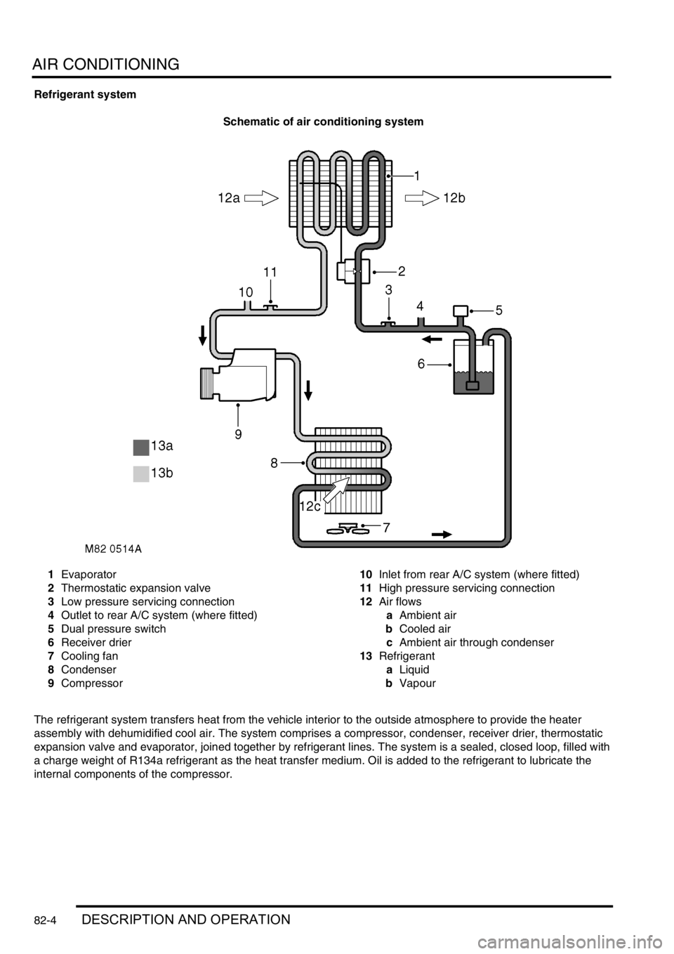
Schematic of air conditioning system
1Evaporator
2Thermostatic expansion valve
3Low pressure servicing connection
4Outlet to rear A/C system (where fitted)
5Dual pressure switch
6Receiver drier
7Cooling fan
8Condenser
9Compressor10Inlet from rear A/C system (where fitted)
11High pressure servicing connection
12Air flows
aAmbient air
bCooled air
cAmbient air through condenser
13Refrigerant
aLiquid
bVapour
The refrigerant system transfers heat from the vehicle interior to the outside atmosphere to provide the heater
assembly with dehumidified cool air. The system comprises a compressor, condenser, receiver drier, thermostatic
expansion valve and evaporator, joined together by refrigerant lines. The system is a sealed, closed loop, filled with
a charge weight of R134a refrigerant as the heat transfer medium. Oil is added to the refrigerant to lubricate the
internal components of the compressor.
Page 1402 of 1672
AIR CONDITIONING
REFRIGERANT RECOVERY, RECYCLING AND RECHARGING 82-29
REFRIGERANT RECOVERY, RECYCLING AND RECHARGING
Refrigerant recovery, recycling and
recharging
$% 82.30.02
Recovery
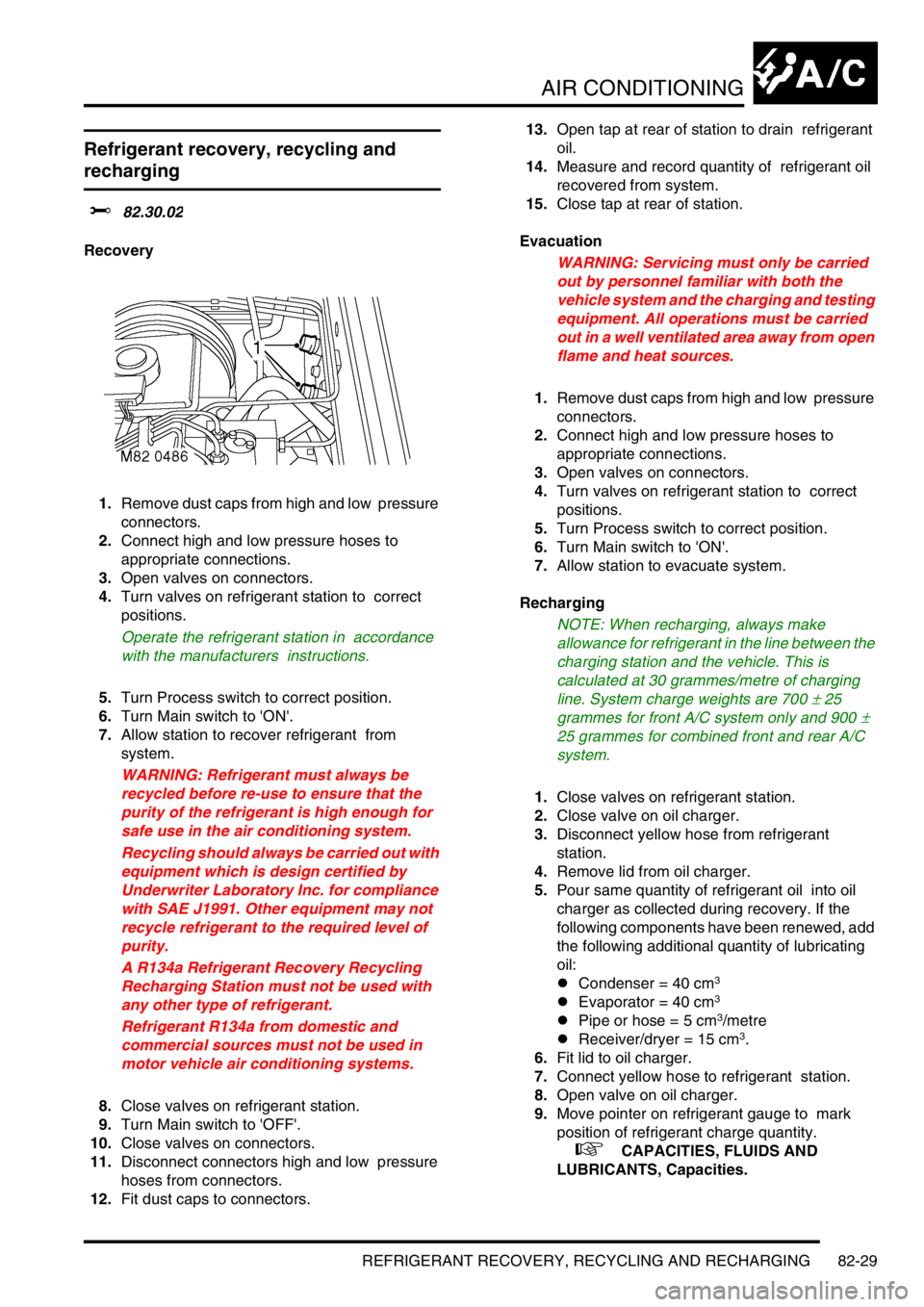
1.Remove dust caps from high and low pressure
connectors.
2.Connect high and low pressure hoses to
appropriate connections.
3.Open valves on connectors.
4.Turn valves on refrigerant station to correct
positions.
Operate the refrigerant station in accordance
with the manufacturers instructions.
5.Turn Process switch to correct position.
6.Turn Main switch to 'ON'.
7.Allow station to recover refrigerant from
system.
WARNING: Refrigerant must always be
recycled before re-use to ensure that the
purity of the refrigerant is high enough for
safe use in the air conditioning system.
Recycling should always be carried out with
equipment which is design certified by
Underwriter Laboratory Inc. for compliance
with SAE J1991. Other equipment may not
recycle refrigerant to the required level of
purity.
A R134a Refrigerant Recovery Recycling
Recharging Station must not be used with
any other type of refrigerant.
Refrigerant R134a from domestic and
commercial sources must not be used in
motor vehicle air conditioning systems.
8.Close valves on refrigerant station.
9.Turn Main switch to 'OFF'.
10.Close valves on connectors.
11.Disconnect connectors high and low pressure
hoses from connectors.
12.Fit dust caps to connectors. 13.Open tap at rear of station to drain refrigerant
oil.
14.Measure and record quantity of refrigerant oil
recovered from system.
15.Close tap at rear of station.
Evacuation
WARNING: Servicing must only be carried
out by personnel familiar with both the
vehicle system and the charging and testing
equipment. All operations must be carried
out in a well ventilated area away from open
flame and heat sources.
1.Remove dust caps from high and low pressure
connectors.
2.Connect high and low pressure hoses to
appropriate connections.
3.Open valves on connectors.
4.Turn valves on refrigerant station to correct
positions.
5.Turn Process switch to correct position.
6.Turn Main switch to 'ON'.
7.Allow station to evacuate system.
Recharging
NOTE: When recharging, always make
allowance for refrigerant in the line between the
charging station and the vehicle. This is
calculated at 30 grammes/metre of charging
line. System charge weights are 700
± 25
grammes for front A/C system only and 900
±
25 grammes for combined front and rear A/C
system.
1.Close valves on refrigerant station.
2.Close valve on oil charger.
3.Disconnect yellow hose from refrigerant
station.
4.Remove lid from oil charger.
5.Pour same quantity of refrigerant oil into oil
charger as collected during recovery. If the
following components have been renewed, add
the following additional quantity of lubricating
oil:
lCondenser = 40 cm
3
lEvaporator = 40 cm3
lPipe or hose = 5 cm3/metre
lReceiver/dryer = 15 cm3.
6.Fit lid to oil charger.
7.Connect yellow hose to refrigerant station.
8.Open valve on oil charger.
9.Move pointer on refrigerant gauge to mark
position of refrigerant charge quantity.
+ CAPACITIES, FLUIDS AND
LUBRICANTS, Capacities.