Page 335 of 1672

EMISSION CONTROL - TD5
17-1-14 REPAIRS
Valve - EGR - Pre EU3 models
$% 17.45.01
On all vehicles up to VIN number 1A736339, the
EGR pipe assembly must be replaced every time the
system is disturbed.
Remove
1.Release turnbuckles and remove battery cover.
2.Disconnect battery earth lead.
3.Remove 3 bolts and remove engine acoustic
cover.
4.Remove cooling fan coupling.
+ COOLING SYSTEM - Td5, REPAIRS,
Fan - viscous.
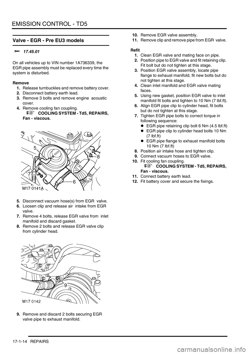
5.Disconnect vacuum hose(s) from EGR valve.
6.Loosen clip and release air intake from EGR
valve.
7.Remove 4 bolts, release EGR valve from inlet
manifold and discard gasket.
8.Remove 2 bolts and release EGR valve clip
from cylinder head.
9.Remove and discard 2 bolts securing EGR
valve pipe to exhaust manifold. 10.Remove EGR valve assembly.
11.Remove clip and remove pipe from EGR valve.
Refit
1.Clean EGR valve and mating face on pipe.
2.Position pipe to EGR valve and fit retaining clip.
Fit bolt but do not tighten at this stage.
3.Position EGR valve assembly, locate pipe
flange to exhaust manifold, fit new bolts but do
not tighten at this stage.
4.Clean inlet manifold and EGR valve mating
faces.
5.Using new gasket, position EGR valve to inlet
manifold fit bolts and tighten to 10 Nm (7 lbf.ft).
6.Align EGR pipe clip to cylinder head, fit bolts
but do not tighten at this stage.
7.Tighten EGR pipe bolts to correct torque in
following sequence:
lEGR pipe retaining clip bolt 6 Nm (4.5 lbf.ft)
lEGR pipe clip to cylinder head bolts 10 Nm
(7 lbf.ft)
lEGR pipe flange to exhaust manifold bolts
10 Nm (7 lbf.ft)
8.Position air intake hose and tighten clip.
9.Connect vacuum hoses to EGR valve.
10.Fit cooling fan coupling.
+ COOLING SYSTEM - Td5, REPAIRS,
Fan - viscous.
11.Connect battery earth lead.
12.Fit battery cover and secure the fixings.
Page 336 of 1672

EMISSION CONTROL - TD5
REPAIRS 17-1-15
Valve - EGR - EU3 models
$% 17.45.01
Remove
1.Release turnbuckles and remove battery cover.
2.Disconnect battery earth lead.
3.Remove 3 bolts and remove engine acoustic
cover.
4.Remove cooling fan coupling.
+ COOLING SYSTEM - Td5, REPAIRS,
Fan - viscous.
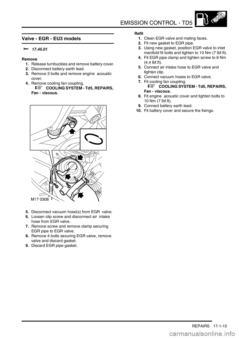
5.Disconnect vacuum hose(s) from EGR valve.
6.Loosen clip screw and disconnect air intake
hose from EGR valve.
7.Remove screw and remove clamp securing
EGR pipe to EGR valve.
8.Remove 4 bolts securing EGR valve, remove
valve and discard gasket.
9.Discard EGR pipe gasket.Refit
1.Clean EGR valve and mating faces.
2.Fit new gasket to EGR pipe.
3.Using new gasket, position EGR valve to inlet
manifold fit bolts and tighten to 10 Nm (7 lbf.ft).
4.Fit EGR pipe clamp and tighten screw to 6 Nm
(4.4 lbf.ft).
5.Connect air intake hose to EGR valve and
tighten clip.
6.Connect vacuum hoses to EGR valve.
7.Fit cooling fan coupling.
+ COOLING SYSTEM - Td5, REPAIRS,
Fan - viscous.
8.Fit engine acoustic cover and tighten bolts to
10 Nm (7 lbf.ft).
9.Connect battery earth lead.
10.Fit battery cover and secure the fixings.
Page 390 of 1672

EMISSION CONTROL - V8
REPAIRS 17-2-53
8.Remove 2 nuts securing air injection pipe to air
intake plenum.
9.Release pipe from clip on rear of air intake
plenum.
10.Release 3 clips securing harness to engine bay
bulkhead.
11.Position container to collect any coolant
spillage.
12.Release clips securing heater hoses to heater.
13.Release hoses from heater.
14.With assistance, manoeuvre air injection pipe
from engine bay.Refit
1.With assistance, manoeuvre air injection pipe
into engine bay and secure onto clip at rear of
air intake plenum.
2.Connect heater hoses to heater and secure
with clips.
3.Reposition harness along engine bay bulkhead
and secure with clips.
4.Fit and tighten nuts securing air injection pipe to
air intake plenum.
5.Connect multiplug to SAI vacuum solenoid.
6.Connect air pump hose to air injection pipe and
secure with clip.
7.Connect LH and RH SAI control valve hoses to
air injection pipe and secure with clips.
8.Remove container.
9.Top up engine coolant.
+ MAINTENANCE, PROCEDURES,
Cooling system.
M17 0231
M17 0232
M17 0233
Page 396 of 1672
ENGINE MANAGEMENT SYSTEM - TD5
DESCRIPTION AND OPERATION 18-1-3
Engine management component
location - engine compartment
LHD illustrated
1Ambient air pressure sensor
2Engine coolant temperature sensor
3Glow plugs
4Engine Control Module (ECM)
5Fuel pump relay
6Main relay
7A/C clutch and cooling fan relays
8Manifold absolute pressure/ inlet air
temperature sensor9Electronic vacuum regulator solenoid
10Fuel temperature sensor
11Crankshaft speed and position sensor
12Electronic unit injectors
13Turbocharger wastegate modulator
14Mass air flow sensor
15Clutch switch
Page 398 of 1672
ENGINE MANAGEMENT SYSTEM - TD5
DESCRIPTION AND OPERATION 18-1-5
1Mass air flow sensor
2Ambient air pressure sensor
3Manifold absolute pressure/ inlet air
temperature sensor
4Engine coolant temperature sensor
5Crankshaft speed and position sensor
6Throttle position sensor
7Fuel temperature sensor
8Brake pedal switch
9Clutch switch
10High/ Low ratio switch
11Main relay
12Malfunction indicator lamp
13Fuel pump relay
14Glow plug warning lamp
15Glow plugs16Electronic unit injectors
17Turbocharger wastegate modulator
18EGR modulator
19Diagnostic connector
20Engine control module
21Cruise control master switch
22Cruise control SET+ switch
23Cruise control RES switch
24Air conditioning clutch relay
25Air conditioning cooling fan relay
26Electronic automatic transmission ECU
27Self levelling and anti-lock brakes ECU
28Instrument cluster
29Body control unit
Page 399 of 1672

ENGINE MANAGEMENT SYSTEM - TD5
18-1-6 DESCRIPTION AND OPERATION
Description
General
An engine control module (ECM) controls the five-cylinder direct injection diesel engine, and works on the drive by
wire principle. This means there is no throttle cable, the ECM controls the drivers needs via a signal from the Throttle
Position (TP) sensor on the throttle pedal.
The ECM is a full authoritative diesel specific microprocessor that also incorporates features for cruise control and air
conditioning control. In addition, the ECM supplies output control for the exhaust gas recirculation and turbocharger
boost pressure. The ECM has a self-diagnostic function, which is able to provide backup strategies for most sensor
failures.
The ECM processes information from the following input sources:
lMass air flow sensor.
lAmbient air pressure sensor.
lManifold absolute pressure/inlet air temperature sensor.
lEngine coolant temperature sensor.
lCrankshaft speed and position sensor.
lThrottle position sensor.
lFuel temperature sensor.
lAir conditioning request.
lAir conditioning fan request.
lBrake pedal switch.
lClutch switch.
lCruise control master switch.
lCruise control SET+ switch.
lCruise control RES switch.
lHigh/low ratio switch.
The input from the sensors constantly updates the ECM with the current operating condition of the engine. Once the
ECM has compared current information with stored information within its memory, it can make any adjustment it
requires to the operation of the engine via the following:
lAir conditioning clutch relay.
lAir conditioning cooling fan relay.
lElectronic vacuum regulator solenoid.
lMalfunction indicator lamp.
lFuel pump relay.
lGlow plug warning lamp.
lGlow plugs.
lFuel injectors.
lMain relay.
lTurbocharger wastegate modulator.
lTemperature gauge.
The ECM interfaces with the following:
lElectronic Automatic Transmission (EAT).
lSelf Levelling and Anti-lock Brakes System (SLABS).
lSerial communication link.
lInstrument cluster.
lBody Control Unit (BCU).
Page 402 of 1672

ENGINE MANAGEMENT SYSTEM - TD5
DESCRIPTION AND OPERATION 18-1-9
Connector C0658
Pin No. Input/Output Function Signal type Value Interfaces
B1 Input Earth 1 0 volts 0 volts
B2 Input Earth 4 0 volts 0 volts
B3 Input Supply battery voltage 12 volts 12 volts
B4 Output Cooling fan relay Switch 12-0 volts A/C ECU
B5 Output Fuel pump relay Switch 12-0 volts
B6 Output MIL Switch 12-0 volts Instruments
B7 Output Temperature gauge Digital 0-12 volts Instruments
B8 Not used
B9 Input A/C clutch request Switch 12-0 volts A/C ECU
B10 Input Normally closed brake
switchSwitch 12-0 volts
B11 Input Cruise control SET+ switch Switch 12-0 volts
B12 Input TP sensor 1 Analogue 0- 5 volts
B13 Input Vehicle speed Digital 0-12 volts
B14 Input TP sensor supply 5 volts 5 volts
B15 Input Cruise control master switch Switch 12-0 volts
B16 Input Normally open brake switch Switch 0-12 volts
B17 Input Cruise control RES switch Switch 12-0 volts
B18 Input/Output Serial communication link Digital 0-12 volts All ECU's
B19 Output Tachometer engine speed Digital 0-12 volts Instrument
Cluster
B20 Not used
B21 Output Main relay Switch 0-12 volts
B22 Input Supply battery voltage 12 volts 12 volts
B23 Input A/C fan request Switch 12-0 volts
B24 Input Earth 3 0 volts 0 volt
B25 Input Earth 2 0 volts 0 volts
B26 Input TP sensor earth 0 volts 0 volts
B27 Input Supply 2 12 volts 12 volts
B28 Not used
B29 Output A/C relay Switch 12-0 volts
B30 Output Glow plug warning light Switch 12-0 volts Instrument
Cluster
B31 Not used
B32 Output ABS digital 0-5 volts SLABS
B33 Input Ignition Switch 0-12 volts
B34 Input Security code digital 0-5 volts
B35 Input Clutch switch Switch 12-0 volts
B36 Input TP sensor 2 Analogue 5-0 volts
Page 407 of 1672

ENGINE MANAGEMENT SYSTEM - TD5
18-1-14 DESCRIPTION AND OPERATION
Engine Coolant Temperature (ECT) sensor
The ECT sensor is located in the coolant outlet elbow on the top of the engine. It provides the ECM with engine coolant
temperature information. The ECM uses this ECT information for the following functions:
lFuelling calculations.
lTemperature gauge.
lTo limit engine operation if coolant temperature is too high.
lCooling fan operation.
lGlow plug operating time.
The ECT works as an NTC sensor. As temperature rises, the resistance in the sensor decreases, as temperature
decreases, the resistance in the sensor increases. The ECM compares the voltage signal to stored values and
compensates fuel delivery to ensure optimum driveability at all times.
Input/Output
The inputs and outputs for the ECT are earth and signal out.
The ECT signal is measured at pin 7 of the ECM connector C0158. The earth path is via pin 18 of ECM connector
C0158.
ECT sensor temperature to resistance table.
Temperature, °C Temperature, °F Resistance, ohms
nominal)
-10 14 9397
0325896
10 50 3792
30 86 1707
50 122 834.0
70 158 435.7
90 194 243.2
110 230 144.2
130 266 89.3