2002 LAND ROVER DISCOVERY battery
[x] Cancel search: batteryPage 335 of 1672

EMISSION CONTROL - TD5
17-1-14 REPAIRS
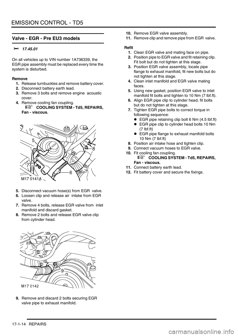
Valve - EGR - Pre EU3 models
$% 17.45.01
On all vehicles up to VIN number 1A736339, the
EGR pipe assembly must be replaced every time the
system is disturbed.
Remove
1.Release turnbuckles and remove battery cover.
2.Disconnect battery earth lead.
3.Remove 3 bolts and remove engine acoustic
cover.
4.Remove cooling fan coupling.
+ COOLING SYSTEM - Td5, REPAIRS,
Fan - viscous.
5.Disconnect vacuum hose(s) from EGR valve.
6.Loosen clip and release air intake from EGR
valve.
7.Remove 4 bolts, release EGR valve from inlet
manifold and discard gasket.
8.Remove 2 bolts and release EGR valve clip
from cylinder head.
9.Remove and discard 2 bolts securing EGR
valve pipe to exhaust manifold. 10.Remove EGR valve assembly.
11.Remove clip and remove pipe from EGR valve.
Refit
1.Clean EGR valve and mating face on pipe.
2.Position pipe to EGR valve and fit retaining clip.
Fit bolt but do not tighten at this stage.
3.Position EGR valve assembly, locate pipe
flange to exhaust manifold, fit new bolts but do
not tighten at this stage.
4.Clean inlet manifold and EGR valve mating
faces.
5.Using new gasket, position EGR valve to inlet
manifold fit bolts and tighten to 10 Nm (7 lbf.ft).
6.Align EGR pipe clip to cylinder head, fit bolts
but do not tighten at this stage.
7.Tighten EGR pipe bolts to correct torque in
following sequence:
lEGR pipe retaining clip bolt 6 Nm (4.5 lbf.ft)
lEGR pipe clip to cylinder head bolts 10 Nm
(7 lbf.ft)
lEGR pipe flange to exhaust manifold bolts
10 Nm (7 lbf.ft)
8.Position air intake hose and tighten clip.
9.Connect vacuum hoses to EGR valve.
10.Fit cooling fan coupling.
+ COOLING SYSTEM - Td5, REPAIRS,
Fan - viscous.
11.Connect battery earth lead.
12.Fit battery cover and secure the fixings.
Page 336 of 1672

EMISSION CONTROL - TD5
REPAIRS 17-1-15
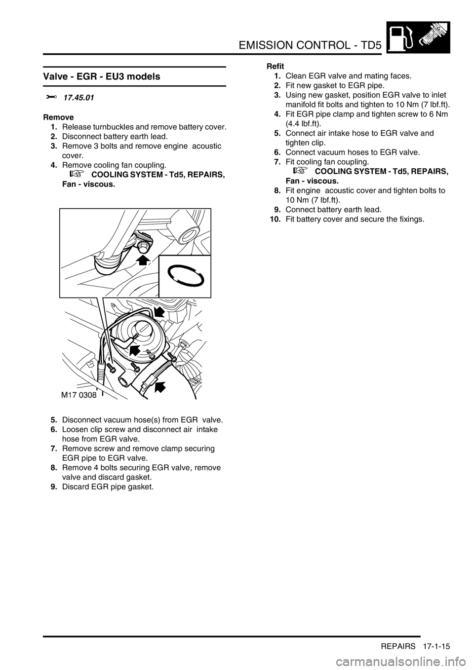
Valve - EGR - EU3 models
$% 17.45.01
Remove
1.Release turnbuckles and remove battery cover.
2.Disconnect battery earth lead.
3.Remove 3 bolts and remove engine acoustic
cover.
4.Remove cooling fan coupling.
+ COOLING SYSTEM - Td5, REPAIRS,
Fan - viscous.
5.Disconnect vacuum hose(s) from EGR valve.
6.Loosen clip screw and disconnect air intake
hose from EGR valve.
7.Remove screw and remove clamp securing
EGR pipe to EGR valve.
8.Remove 4 bolts securing EGR valve, remove
valve and discard gasket.
9.Discard EGR pipe gasket.Refit
1.Clean EGR valve and mating faces.
2.Fit new gasket to EGR pipe.
3.Using new gasket, position EGR valve to inlet
manifold fit bolts and tighten to 10 Nm (7 lbf.ft).
4.Fit EGR pipe clamp and tighten screw to 6 Nm
(4.4 lbf.ft).
5.Connect air intake hose to EGR valve and
tighten clip.
6.Connect vacuum hoses to EGR valve.
7.Fit cooling fan coupling.
+ COOLING SYSTEM - Td5, REPAIRS,
Fan - viscous.
8.Fit engine acoustic cover and tighten bolts to
10 Nm (7 lbf.ft).
9.Connect battery earth lead.
10.Fit battery cover and secure the fixings.
Page 342 of 1672

EMISSION CONTROL - V8
DESCRIPTION AND OPERATION 17-2-5
Evaporative emission system control
diagram
1Battery
2Fuse 13 (engine compartment fusebox)
3Inertia switch
4Main relay (engine compartment fusebox)
5Engine Control Module (ECM)
6Purge Valve (black harness connector)
7Canister vent solenoid (CVS) valve – NAS
vehicles with vacuum type EVAP system leak
detection capability only8Leak detection pump – NAS vehicles with
positive pressure type EVAP system leak
detection capability only
9Fuel tank pressure sensor – NAS vehicles with
vacuum type EVAP system leak detection
capability only
10Instrument pack (MIL warning light)
M17 0210
12
3
4
5
6
7
9
8
10
Page 345 of 1672

EMISSION CONTROL - V8
17-2-8 DESCRIPTION AND OPERATION
Secondary air injection system control
diagram
1Fuselink 2 (engine compartment fusebox)
2SAI pump relay
3SAI pump
4SAI vacuum solenoid valve (grey harness
connector)
5Engine Control Module (ECM)6Battery
7Fuse 13 (engine compartment fusebox)
8Inertia switch
9Main relay
9
M17 0207
1
2
3
4
5
7
6
8
Page 357 of 1672

EMISSION CONTROL - V8
17-2-20 DESCRIPTION AND OPERATION
Purge valve operation is controlled by the engine control module (ECM). The purge valve has a two-pin electrical
connector which links to the ECM via the engine harness. Pin-1 of the connector is the power supply source from fuse
2 in the engine compartment fusebox, and pin-2 of the connector is the switched earth from the ECM (pulse width
modulated (PWM) signal) which is used to control the purge valve operation time. Note that the harness connector
for the purge valve is black, and must not be confused with the connector for the Secondary Air Injection
vacuum solenoid valve which is grey.
When the purge valve is earthed by the ECM, the valve opens to allow hydrocarbons stored in the EVAP canister to
be purged to the engine inlet manifold for combustion.
If the purge valve breaks or becomes stuck in the open or closed position, the EVAP system will cease to function
and there are no default measures available. The ECM will store the fault in memory and illuminate the MIL warning
lamp if the correct monitoring conditions have been achieved (i.e. valve status unchanged for 45 seconds after engine
has been running for 15 minutes). If the purge valve is stuck in the open position, a rich air:fuel mixture is likely to
result at the intake manifold, this could cause the engine to misfire and the fuelling adaptions will change.
The following failure modes are possible:
lSticking valve
lValve blocked
lConnector or harness wiring fault (open or short circuit)
lValve stuck open
If the purge valve malfunctions, the following fault codes may be stored in the ECM diagnostic memory, which can be
retrieved using 'Testbook':
P-code Description
P0440Purge valve not sealing
P0444Purge valve open circuit
P0445Purge valve short circuit to ground
P0443Purge valve short circuit to battery voltage
Page 359 of 1672

EMISSION CONTROL - V8
17-2-22 DESCRIPTION AND OPERATION
The following failure modes are possible:
lConnector or harness wiring fault (open or short circuit)
lValve stuck open or shut
lValve blocked
If the CVS valve malfunctions, the following fault codes may be stored in the ECM diagnostic memory, which can be
retrieved using 'Testbook':
Fuel Tank Pressure Sensor (NAS vehicles with vacuum type leak detection system only)
1Ambient pressure
2Tank pressure
3Sensor cell
The fuel tank pressure sensor is located in the top flange of the fuel tank sender / fuel pump module and is a non-
serviceable item (i.e. if the sensor becomes defective, the complete fuel tank sender unit must be replaced). The fuel
tank pressure sensor connector is accessible through the fuel pump access hatch in the boot area floor of the vehicle.
The pressure sensor is a piezo-resistive sensor element with associated circuitry for signal amplification and
temperature compensation. The active surface is exposed to ambient pressure by an opening in the cap and by the
reference port. It is protected from humidity by a silicon gel. The tank pressure is fed up to a pressure port at the back
side of the diaphragm.
P-code Description
P0446CVS valve / pipe blocked
P0447CVS valve open circuit
P0448CVS valve short circuit to ground
P0449CVS valve short circuit to battery voltage
Page 360 of 1672

EMISSION CONTROL - V8
DESCRIPTION AND OPERATION 17-2-23
For systems utilising the vacuum method for determining evaporation leaks, the sensor is used to monitor for a drop
in vacuum pressure. The evaporation system is sealed by the CVS valve and purge valve after a vacuum has been
previously set up from the intake manifold while the purge valve is open and the CVS valve is closed. If any holes or
leaks are present at the evaporation system joints, the vacuum pressure will gradually drop and this change in
pressure will be detected by the fuel tank pressure sensor. This system is capable of determining leaks down to 1 mm
(0.04 in.) in diameter.
The fuel tank pressure sensor is part of the NAS OBD system, a component failure will not be noticed by the driver,
but if the ECM detects a fault, it will be stored in the diagnostic memory and the MIL light will be illuminated on the
instrument pack. Possible failures are listed below:
lDamaged or blocked sensor
lHarness / connector faulty
lSensor earthing problem
lOpen circuit
lShort circuit to battery voltage
lShort circuit to ground
lECM fault
Possible failure symptoms of the fuel tank pressure sensor are listed below:
lFuel tank pressure sensor poor performance
lFuel tank pressure sensor low range fault
lFuel tank pressure sensor high range fault
If the fuel tank pressure sensor should malfunction, the following fault codes may be stored in the ECM diagnostic
memory, which can be retrieved using 'Testbook':
P-code Description
P0451Fuel tank pressure signal stuck high within range
P0452Fuel tank pressure signal short circuit to battery voltage (out of range - High)
P0453Fuel tank pressure signal short circuit to ground or open circuit (out of range - Low)
Page 365 of 1672

EMISSION CONTROL - V8
17-2-28 DESCRIPTION AND OPERATION
The SAI pump is attached to a bracket at the rear RH side of the engine compartment and is fixed to the bracket by
three studs and nuts. The pump is electrically powered from a 12V battery supply via a dedicated relay and supplies
approximately 35kg/hr of air when the vehicle is at idle in Neutral/Park on a start from 20
°C (68°F).
Air is drawn into the pump through vents in its front cover and is then passed through a foam filter to remove
particulates before air injection. The air is delivered to the exhaust manifold on each side of the engine through a
combination of plastic and metal pipes.
The air delivery pipe is a flexible plastic type, and is connected to the air pump outlet via a plastic quick-fit connector.
The other end of the flexible plastic pipe connects to the fixed metal pipework via a short rubber hose. The part of the
flexible plastic pipe which is most vulnerable to engine generated heat is protected by heat reflective sleeving. The
metal delivery pipe has a fabricated T-piece included where the pressurised air is split for delivery to each exhaust
manifold via the SAI control valves.
The pipes from the T-piece to each of the SAI control valves are approximately the same length, so that the pressure
and mass of the air delivered to each bank will be equal. The ends of the pipes are connected to the inlet port of each
SAI control valve through short rubber hose connections.
The T-piece is mounted at the rear of the engine (by the ignition coils) and features a welded mounting bracket which
is fixed to the engine by two studs and nuts.
The foam filter in the air intake of the SAI pump provides noise reduction and protects the pump from damage due to
particulate contamination. In addition, the pump is fitted on rubber mountings to help prevent noise which is generated
by pump operation from being transmitted through the vehicle body into the passenger compartment.
If the secondary air injection pump malfunctions, the following fault codes may be stored in the ECM diagnostic
memory, which can be retrieved using 'Testbook':
Secondary air injection (SAI) pump relay
The secondary air injection pump relay is located in the engine compartment fusebox. The engine control module
(ECM) is used to control the operation of the SAI pump via the SAI pump relay. Power to the coil of the relay is supplied
from the vehicle battery via the main relay and the ground connection to the coil is via the ECM.
Power to the SAI pump relay contacts is via fusible link FL2 which is located in the engine compartment fusebox.
P-code Description
P0418Secondary air injection pump powerstage fault (e.g. - SAI pump relay fault / SAI
pump or relay not connected / open circuit / harness damage).