2002 LAND ROVER DISCOVERY warning light
[x] Cancel search: warning lightPage 1082 of 1672
BRAKES
REPAIRS 70-37
Switch - brake light
$% 70.35.42
The brake switch is set automatically during fitment.
If the setting is disturbed, the switch can be reset by
depressing the brake pedal and pulling the plunger
out of the switch body, until it contacts the pedal.
Remove
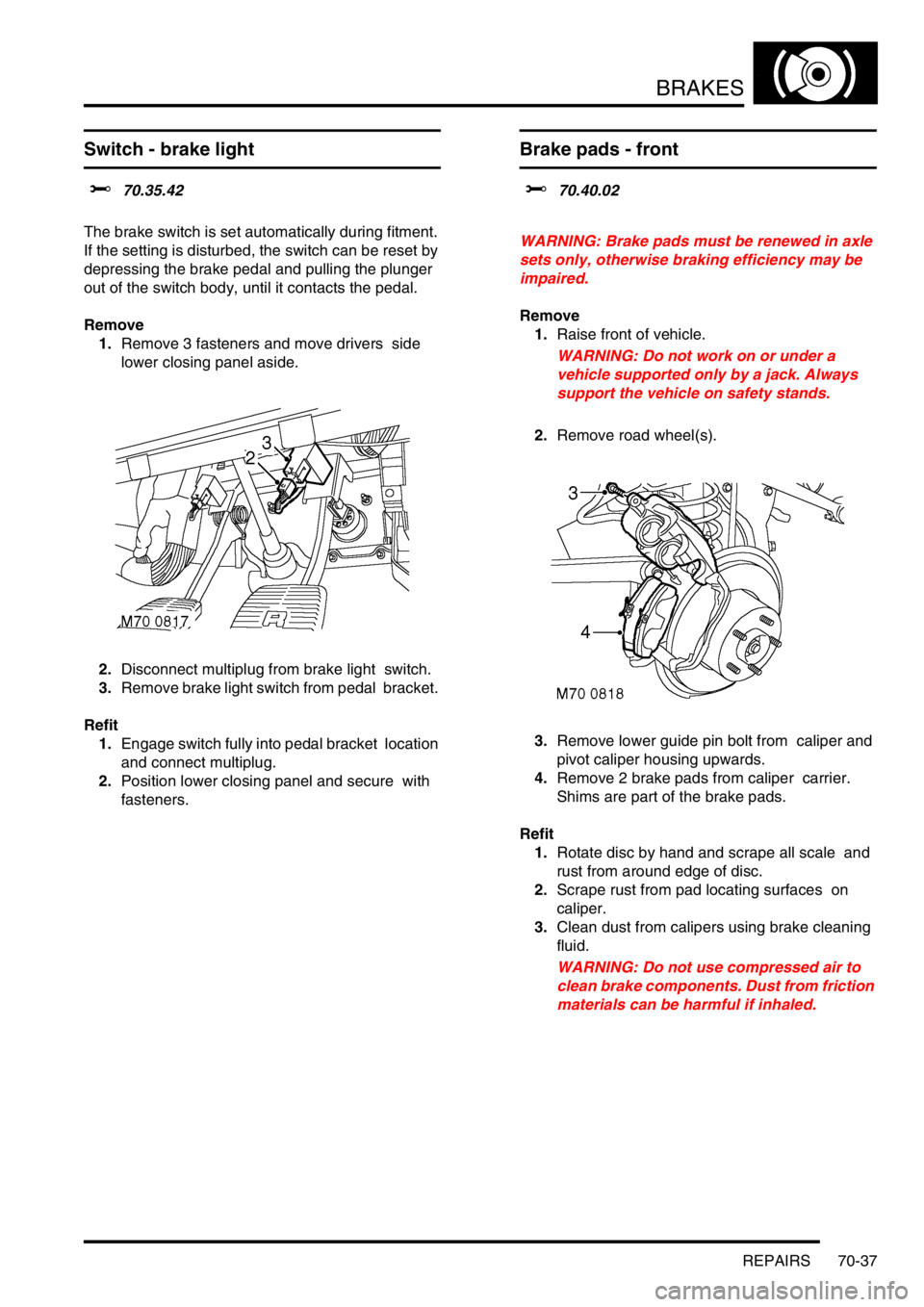
1.Remove 3 fasteners and move drivers side
lower closing panel aside.
2.Disconnect multiplug from brake light switch.
3.Remove brake light switch from pedal bracket.
Refit
1.Engage switch fully into pedal bracket location
and connect multiplug.
2.Position lower closing panel and secure with
fasteners.
Brake pads - front
$% 70.40.02
WARNING: Brake pads must be renewed in axle
sets only, otherwise braking efficiency may be
impaired.
Remove
1.Raise front of vehicle.
WARNING: Do not work on or under a
vehicle supported only by a jack. Always
support the vehicle on safety stands.
2.Remove road wheel(s).
3.Remove lower guide pin bolt from caliper and
pivot caliper housing upwards.
4.Remove 2 brake pads from caliper carrier.
Shims are part of the brake pads.
Refit
1.Rotate disc by hand and scrape all scale and
rust from around edge of disc.
2.Scrape rust from pad locating surfaces on
caliper.
3.Clean dust from calipers using brake cleaning
fluid.
WARNING: Do not use compressed air to
clean brake components. Dust from friction
materials can be harmful if inhaled.
Page 1120 of 1672
RESTRAINT SYSTEMS
REPAIRS 75-25
Airbag module - passenger - deployment
$% 76.74.99
These guidelines are written to aid authorised
personnel to carry out the safe disposal of airbag
modules when removed from the vehicle.
If a vehicle is to be scrapped and contains an
undeployed airbag module, the module must be
manually deployed. This operation should only
be carried out using the following recommended
manual deployment procedure. Before
deployment is started the deployment tool self
test procedure should be carried out.
WARNING: Only use approved deployment
equipment, and only deploy SRS components in
a well ventilated designated area. Ensure SRS
components are not damaged or ruptured before
deployment. Notify the relevant authorities.
Deploy
1.Carry out deployment tool self test.
+ RESTRAINT SYSTEMS, REPAIRS,
Airbag deployment tool - self test.
2.Remove airbag module from fascia.
+ RESTRAINT SYSTEMS, REPAIRS,
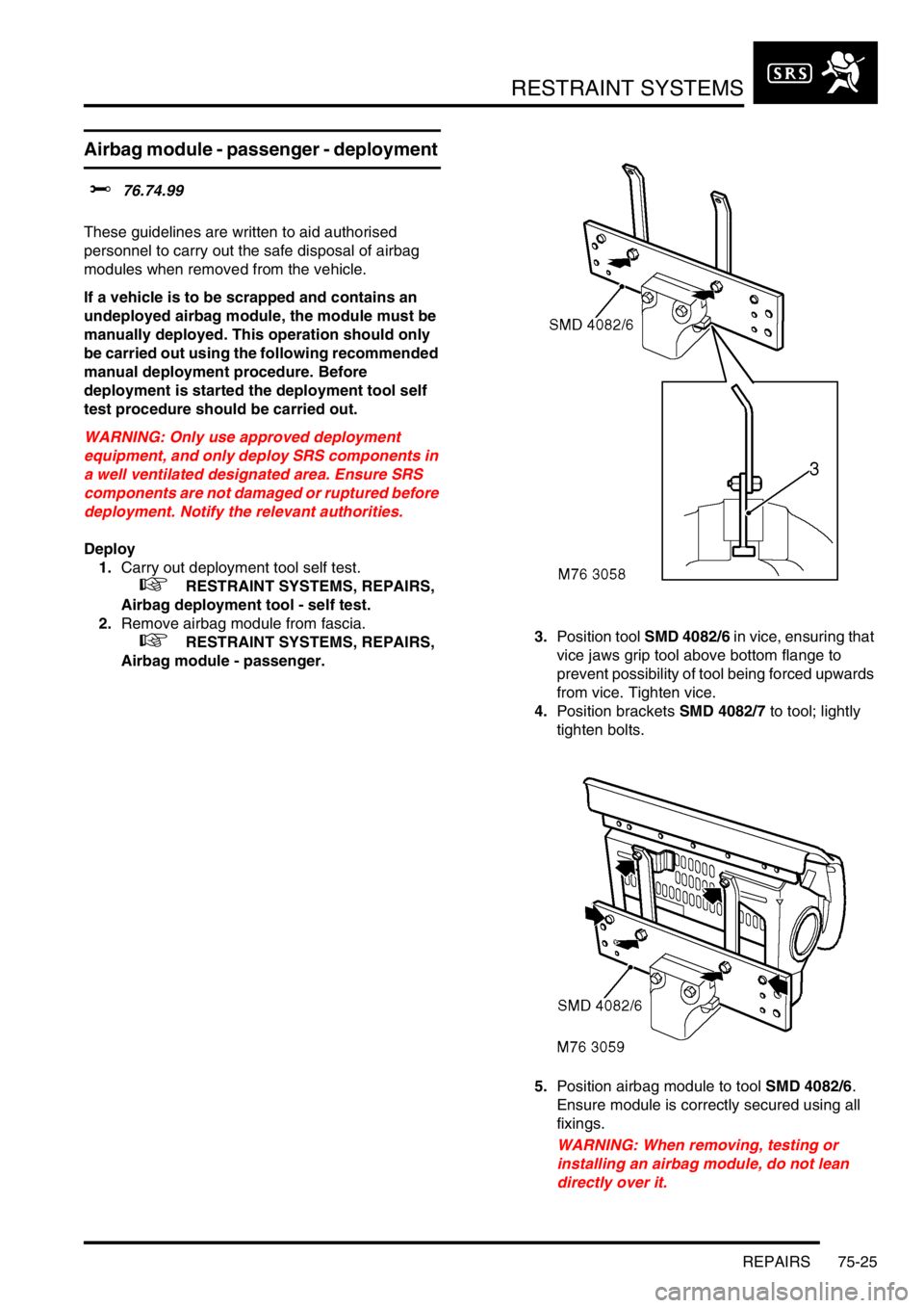
Airbag module - passenger.3.Position tool SMD 4082/6 in vice, ensuring that
vice jaws grip tool above bottom flange to
prevent possibility of tool being forced upwards
from vice. Tighten vice.
4.Position brackets SMD 4082/7 to tool; lightly
tighten bolts.
5.Position airbag module to tool SMD 4082/6.
Ensure module is correctly secured using all
fixings.
WARNING: When removing, testing or
installing an airbag module, do not lean
directly over it.
Page 1181 of 1672
SCREENS
76-4-4 REPAIRS
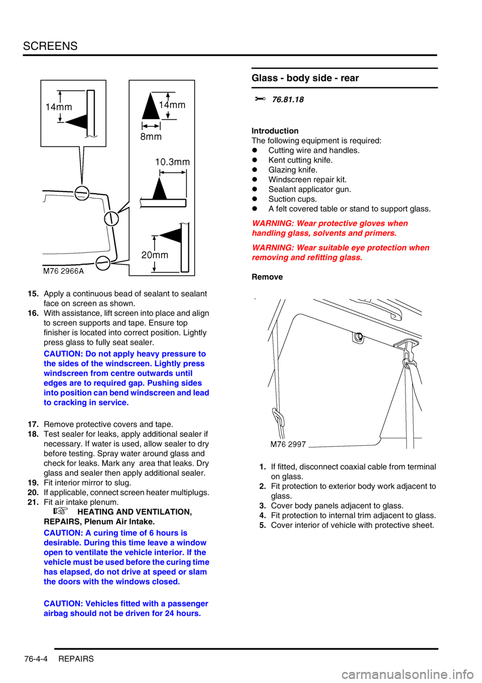
15.Apply a continuous bead of sealant to sealant
face on screen as shown.
16.With assistance, lift screen into place and align
to screen supports and tape. Ensure top
finisher is located into correct position. Lightly
press glass to fully seat sealer.
CAUTION: Do not apply heavy pressure to
the sides of the windscreen. Lightly press
windscreen from centre outwards until
edges are to required gap. Pushing sides
into position can bend windscreen and lead
to cracking in service.
17.Remove protective covers and tape.
18.Test sealer for leaks, apply additional sealer if
necessary. If water is used, allow sealer to dry
before testing. Spray water around glass and
check for leaks. Mark any area that leaks. Dry
glass and sealer then apply additional sealer.
19.Fit interior mirror to slug.
20.If applicable, connect screen heater multiplugs.
21.Fit air intake plenum.
+ HEATING AND VENTILATION,
REPAIRS, Plenum Air Intake.
CAUTION: A curing time of 6 hours is
desirable. During this time leave a window
open to ventilate the vehicle interior. If the
vehicle must be used before the curing time
has elapsed, do not drive at speed or slam
the doors with the windows closed.
CAUTION: Vehicles fitted with a passenger
airbag should not be driven for 24 hours.
Glass - body side - rear
$% 76.81.18
Introduction
The following equipment is required:
lCutting wire and handles.
lKent cutting knife.
lGlazing knife.
lWindscreen repair kit.
lSealant applicator gun.
lSuction cups.
lA felt covered table or stand to support glass.
WARNING: Wear protective gloves when
handling glass, solvents and primers.
WARNING: Wear suitable eye protection when
removing and refitting glass.
Remove
1.If fitted, disconnect coaxial cable from terminal
on glass.
2.Fit protection to exterior body work adjacent to
glass.
3.Cover body panels adjacent to glass.
4.Fit protection to internal trim adjacent to glass.
5.Cover interior of vehicle with protective sheet.
Page 1183 of 1672
SCREENS
76-4-6 REPAIRS
Glass - alpine light
$% 76.81.52
Introduction
The following equipment is required:
lCutting wire and handles.
lKent cutting knife.
lGlazing knife.
lWindscreen repair kit.
lSealant applicator gun.
lSuction cups.
lA felt covered table or stand to support glass.
WARNING: Wear protective gloves when
handling glass, solvents and primers.
WARNING: Wear suitable eye protection when
removing and refitting glass.
Remove
1.Fit protection to exterior body work adjacent to
glass.
2.Fit cover over adjacent body work.
3.Fit protection to internal trim adjacent to glass.
4.Cover interior of vehicle with protective sheet.
5.From outside of vehicle, use a Kent knife and
carefully cut through sealant to release glass
from body. Any remaining sealant not
accessible with Kent knife can be severed
using cutting wire or knife.
CAUTION: Hold the cutting wire as close to
the glass as possible to prevent damage to
the body and surrounding trim.
6.Remove glass.
CAUTION: Lay glass on felt covered
supports and be careful not to damage the
obscuration band. Do not stand on edge as
this can cause chips which subsequently
develop into cracks.Refit
1.Carefully remove sealant from body to leave a
smooth surface.
2.With assistance, fit glass without sealant to
body and apply masking tape to establish
reference marks as an alignment aid.
3.Remove glass and place aside.
4.Clean body and sealant face on glass with
solvent.
CAUTION: Do not touch cleaned or primed
surfaces with fingers.
5.Apply etch primer to any bare metal on body.
6.Apply glass primer to sealant face on glass and
allow to cure.
7.Apply primer over etch primer on body.
8.Apply activator over old sealant on body.
9.Allow activator to cure.
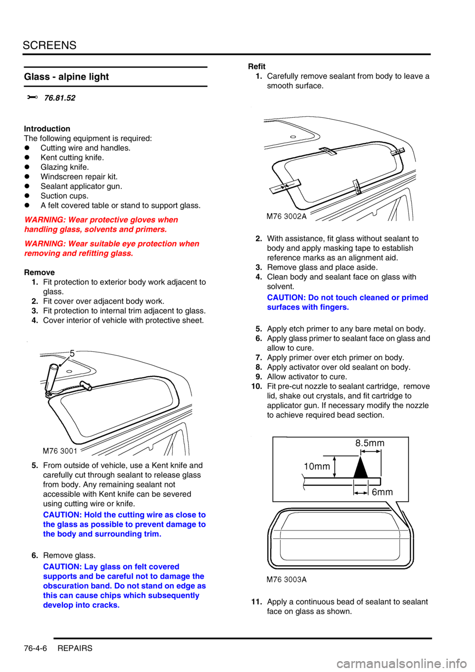
10.Fit pre-cut nozzle to sealant cartridge, remove
lid, shake out crystals, and fit cartridge to
applicator gun. If necessary modify the nozzle
to achieve required bead section.
11.Apply a continuous bead of sealant to sealant
face on glass as shown.
Page 1390 of 1672

AIR CONDITIONING
DESCRIPTION AND OPERATION 82-17
RH temperature. Illuminates to show the RH temperature selection, external air temperature or diagnostic fault code.
Blower speed. Illuminates when the blower speed is manually selected. Also illuminates in the automatic modes when
one of the temperatures is set to LO or HI.
External air temperature. EXT illuminates to show that external air temperature is selected on.
All temperature indications on the display are in either
°C or °F. For 1 second after the system is first switched on, the
display shows only
°C or °F, in the LH temperature window, to indicate which temperature scale is in use. After 1
second, the
°C or °F indication goes off and the display shows all relevant outputs.
Temperature conversion: While the system is on, the temperature indications on the display can be switched between
the two scales by pressing and holding the fresh/recirculated air switch, then pressing and holding the A/C on/off
switch until the audible warning sounds (approximately 3 seconds).
Dual pressure switch
The dual pressure switch protects the refrigerant system from extremes of pressure. The normally closed switch is
installed in the top of the receiver drier. If minimum or maximum pressure limits are exceeded the switch contacts
open, causing the compressor clutch to be disengaged. The minimum pressure limit protects the compressor, by
preventing operation of the system unless there is a minimum refrigerant pressure (and thus refrigerant and
lubricating oil) in the system. The maximum pressure limit keeps the refrigerant system within a safe operating
pressure.
Dual pressure switch nominal operating pressures
Evaporator temperature sensor
The evaporator temperature sensor is an encapsulated thermistor that provides the ATC ECU with an input of the
evaporator air outlet temperature. The evaporator temperature sensor is installed in a clip which locates in the
evaporator matrix in the heater assembly. The ATC ECU uses the input to prevent the formation of ice on the
evaporator.
In-car temperature sensor
The in-car temperature sensor is an encapsulated thermistor that provides the ATC ECU with an input of cabin air
temperature. The sensor is integrated into the inlet of an electric fan, which is installed behind a grille in the fascia
outboard of the steering column. The fan runs continuously, while the ignition is on, to draw air through the grille and
across the sensor.
Sunlight sensor
The sunlight sensor consists of two diodes that provide the ATC ECU with inputs of light intensity, one as sensed
coming from the left of the vehicle and one as sensed coming from the right. The inputs are used as a measure of the
solar heating effect on vehicle occupants. The sensor is installed in the centre of the fascia upper surface.
Heater coolant temperature sensor
The heater coolant temperature sensor is an encapsulated thermistor that provides the ATC ECU with an input related
to heater matrix coolant temperature. The sensor is installed in the casing of the heater assembly and presses against
the end tank of the heater matrix.
Ambient temperature sensor
The ambient temperature sensor is an encapsulated thermistor that provides the ATC ECU with an input of external
air temperature. The sensor is attached to the cooling fan mounting bracket in front of the condenser.
Limit Opening pressure, bar (lbf.in2) Closing pressure, bar (lbf.in2)
Minimum 2.0 (29.0), pressure decreasing 2.3 (33.4), pressure increasing
Maximum 32 (464), pressure increasing 26 (377), pressure decreasing
Page 1394 of 1672

AIR CONDITIONING
DESCRIPTION AND OPERATION 82-21
Diagnostics
The ATC ECU performs a diagnostic check each time the ignition is switched on. To avoid nuisance fault indications
at low light levels, the sunlight sensor is omitted from the diagnostic check. If a fault is detected, the audible warning
sounds three times and the AUTO window on the control panel display flashes for 20 seconds. The ATC ECU then
reverts to normal control but uses a default value or strategy for the detected fault. Faults are identified by performing
a manual diagnostic check of the system.
A manual diagnostic check includes a check of the sunlight sensor, and is initiated by pressing and holding the AUTO
switch and the air distribution switch, then turning the ignition switch from off to on. The audible warning sounds once
and the indications on the control panel display illuminate. FC is shown in the LH temperature window and the results
of the check are shown as a two digit fault code in the RH temperature window. If a fault is detected, the audible
warning sounds three times and the AUTO window on the display flashes on and off for 20 seconds. If more than one
fault is detected, the fault codes cycle in numerical order, at 1 Hz. The audible warning sounds as each fault code is
shown. In low light conditions, to avoid false sunlight sensor fault indications, the sunlight sensor should be illuminated
with a strong light source.
Diagnostic fault codes and fault descriptions
Code Component Fault Default value/strategy
00 - No fault found -
11 In-car temperature sensor Open or short circuit 25°C (77°F)
12 Ambient temperature sensor Open or short circuit 10°C (50°F)
Cooling fan permanently on
Display shows "- -" if external
air temperature selected
13 Thermistor Open or short circuit 0°C (32°F)
14 Heater coolant temperature sensor Open or short circuit 70°C (158°F)
21 Sunlight sensor, left output Open or short circuit No solar heating correction
22 Sunlight sensor, right output Open or short circuit No solar heating correction
31 LH temperature servo motor Open or short circuit
Motor or flap mechanism seizedServo motor locked in position
32 RH temperature servo motor Open or short circuit
Motor or flap mechanism seizedServo motor locked in position
33 Distribution servo motor Open or short circuit
Motor or flap mechanism seizedServo motor locked in position
Page 1468 of 1672
LIGHTING
REPAIRS 86-2-13
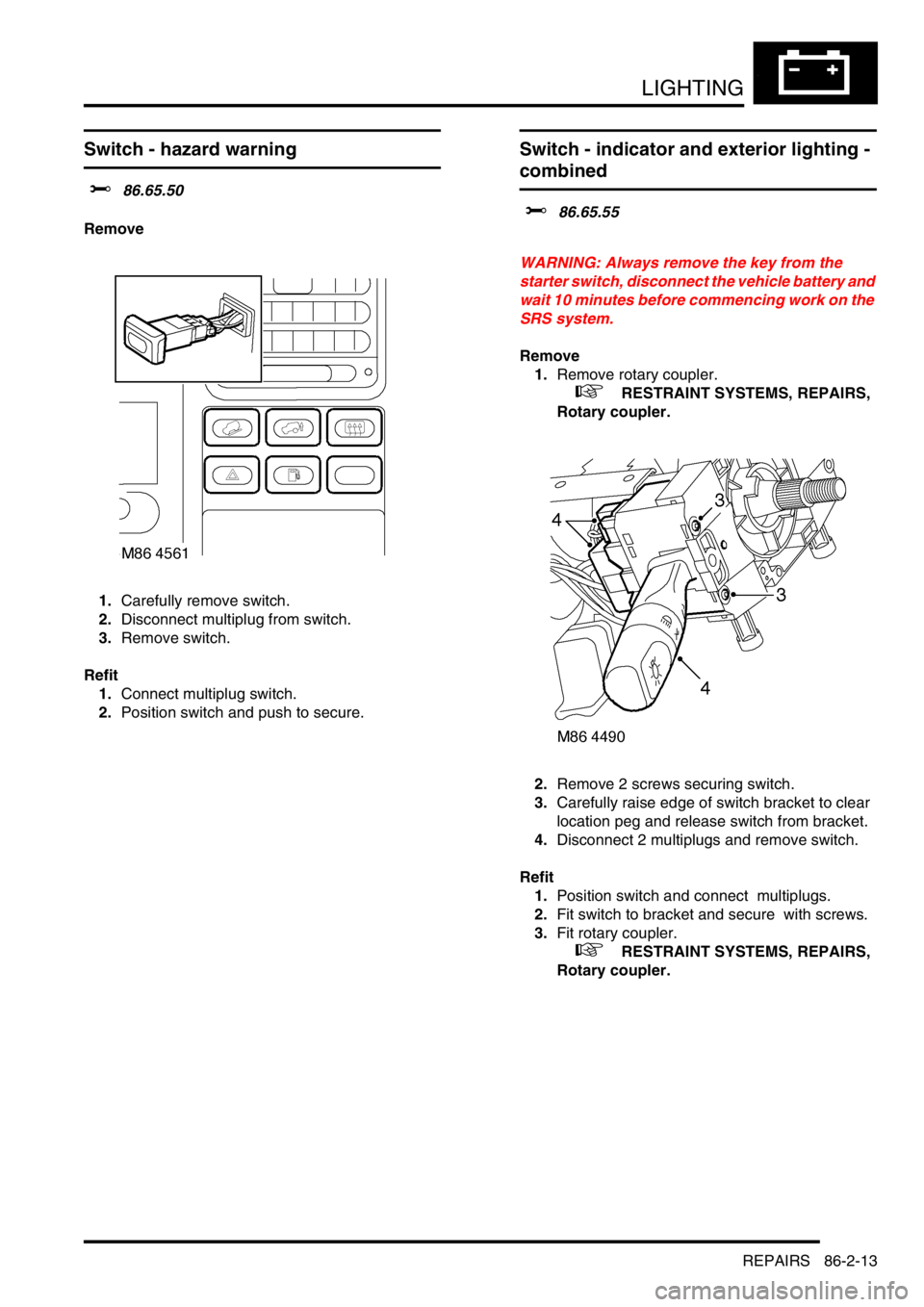
Switch - hazard warning
$% 86.65.50
Remove
1.Carefully remove switch.
2.Disconnect multiplug from switch.
3.Remove switch.
Refit
1.Connect multiplug switch.
2.Position switch and push to secure.
Switch - indicator and exterior lighting -
combined
$% 86.65.55
WARNING: Always remove the key from the
starter switch, disconnect the vehicle battery and
wait 10 minutes before commencing work on the
SRS system.
Remove
1.Remove rotary coupler.
+ RESTRAINT SYSTEMS, REPAIRS,
Rotary coupler.
2.Remove 2 screws securing switch.
3.Carefully raise edge of switch bracket to clear
location peg and release switch from bracket.
4.Disconnect 2 multiplugs and remove switch.
Refit
1.Position switch and connect multiplugs.
2.Fit switch to bracket and secure with screws.
3.Fit rotary coupler.
+ RESTRAINT SYSTEMS, REPAIRS,
Rotary coupler.
Page 1470 of 1672

BODY CONTROL UNIT
DESCRIPTION AND OPERATION 86-3-1
BODY CONTROL UNIT DESCRIPTION AND OPERAT ION
Description
General
The Body Control Unit (BCU) is located behind the passenger glovebox and is connected to the main harness by four
connectors on its bottom edge and an additional connector located on the side of the BCU casing. Mounting the BCU
behind the fascia makes it reasonably inaccessible for intruders to disable the anti-theft system.
The BCU uses solid-state microprocessor control to perform logical operations and timing functions for a variety of
the vehicle's electrically operated systems, these include:
lDoor locking.
lAnti-theft alarm and immobilisation system.
lExterior lighting including direction indicators and hazard warning lamps.
lCourtesy lighting.
lWipers and washers.
lElectric windows and sunroof.
lHeated windows.
The BCU also communicates with several other electronically controlled systems such as the EAT ECU and SLABS
ECU and also has a datalink between the Intelligent Driver Module (IDM) and the instrument pack. The datalink is a
low speed bus capable of transmitting and receiving messages at a data rate of 10,400 bits per second. Additional
inputs and outputs to peripheral devices are included which are necessary for determining vehicle status for particular
logical operations e.g. crank, ignition key inserted, fuel flap enable etc.
The BCU receives its power supply from the engine compartment fuse box, and is protected by a 10 A fuse.
The BCU communicates with the IDM to provide the control signals to perform power switching operations in
conjunction with dedicated relays.
IDM
The IDM is integrated into the passenger compartment fuse box, which is mounted behind the fascia below the
steering column. There are no harnesses between the fuse box and the IDM. The IDM performs the power switching
operations for several of the vehicle's electrical systems.
The IDM communicates with the BCU and the instrument pack via a serial interface. If the BCU or the IDM is replaced,
the communications link between the two units has to be re-established. This can be done either by switching on the
ignition and leaving it on for five minutes, or by using TestBook. The vehicle immobilisation will remain active until the
communications link between the BCU and IDM has been re-established.
Transit mode
To prevent excessive battery drain during transit to overseas markets, the vehicle is placed in a transit mode. The
following functions are disabled when the vehicle is in transit mode:
lVolumetric sensors.
lPassive immobilisation.
lImmobilisation of the vehicle by use of door lock.
lIgnition key interlock.
lElectric seat enable time-out with driver's door open.