2002 LAND ROVER DISCOVERY ignition
[x] Cancel search: ignitionPage 1607 of 1672
DRIVING AIDS
86-8-8 DESCRIPTION AND OPERATION
PDC Switch
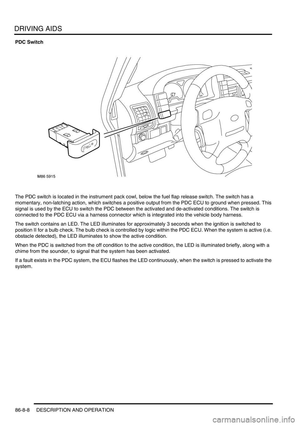
The PDC switch is located in the instrument pack cowl, below the fuel flap release switch. The switch has a
momentary, non-latching action, which switches a positive output from the PDC ECU to ground when pressed. This
signal is used by the ECU to switch the PDC between the activated and de-activated conditions. The switch is
connected to the PDC ECU via a harness connector which is integrated into the vehicle body harness.
The switch contains an LED. The LED illuminates for approximately 3 seconds when the ignition is switched to
position II for a bulb check. The bulb check is controlled by logic within the PDC ECU. When the system is active (i.e.
obstacle detected), the LED illuminates to show the active condition.
When the PDC is switched from the off condition to the active condition, the LED is illuminated briefly, along with a
chime from the sounder, to signal that the system has been activated.
If a fault exists in the PDC system, the ECU flashes the LED continuously, when the switch is pressed to activate the
system.
Page 1609 of 1672

DRIVING AIDS
86-8-10 DESCRIPTION AND OPERATION
Operation
PDC System Operation
When the ignition switch is in position II and reverse gear is selected, the PDC sensors are automatically activated.
The PDC ECU only activates the system if reverse is selected for more than 1 second. This avoids nuisance audible
warnings when the gear selector lever is being moved between Drive and Park on vehicles with automatic
transmission.
When the system is activated, the PDC ECU illuminates the indicator LED in the PDC switch, switches on the
ultrasonic sensors and generates a single chime on the PDC sounder to indicate the system is active. If an object is
range of the sensors when the system is activated, a series of audible warnings are emitted by the PDC sounder
immediately.
If PDC operation is not required, it can be suspended temporarily by pressing the PDC switch. When reverse is
deselected and subsequently reselected, PDC will automatically become active again.
PDC can also be manually selected when not in reverse gear by pressing the PDC switch. A second press of the
switch is required to turn off the PDC or the PDC will be deactivated if reverse is selected and then deselected.
Sensor Operation
The PDC ECU processes the distance readings from the ultrasonic sensors to determine if there are any objects
within the detection areas. If there are no objects in the detection areas, there are no further audible warnings. If an
object is detected, repeated audible warnings are produced on the PDC sounder.
The maximum detection range is 1800 mm (70 in). When an object is detected, the time delay between the audible
warning tones decreases as the distance between the detected object and the vehicle decreases until, at
approximately 450 mm (17 in), the audible warning tone is continuous.
After the initial detection of an object, if there is no decrease in the distance between an object and the central sensors,
the time delay between the audible warnings remains constant. If an object is detected by one of the corner sensors
only, the audible warnings stop after about 5 seconds if there is no change in the distance between the object and the
corner sensor.
Page 1619 of 1672
NAVIGATION SYSTEM
87-4 DESCRIPTION AND OPERATION
Inputs and Outputs
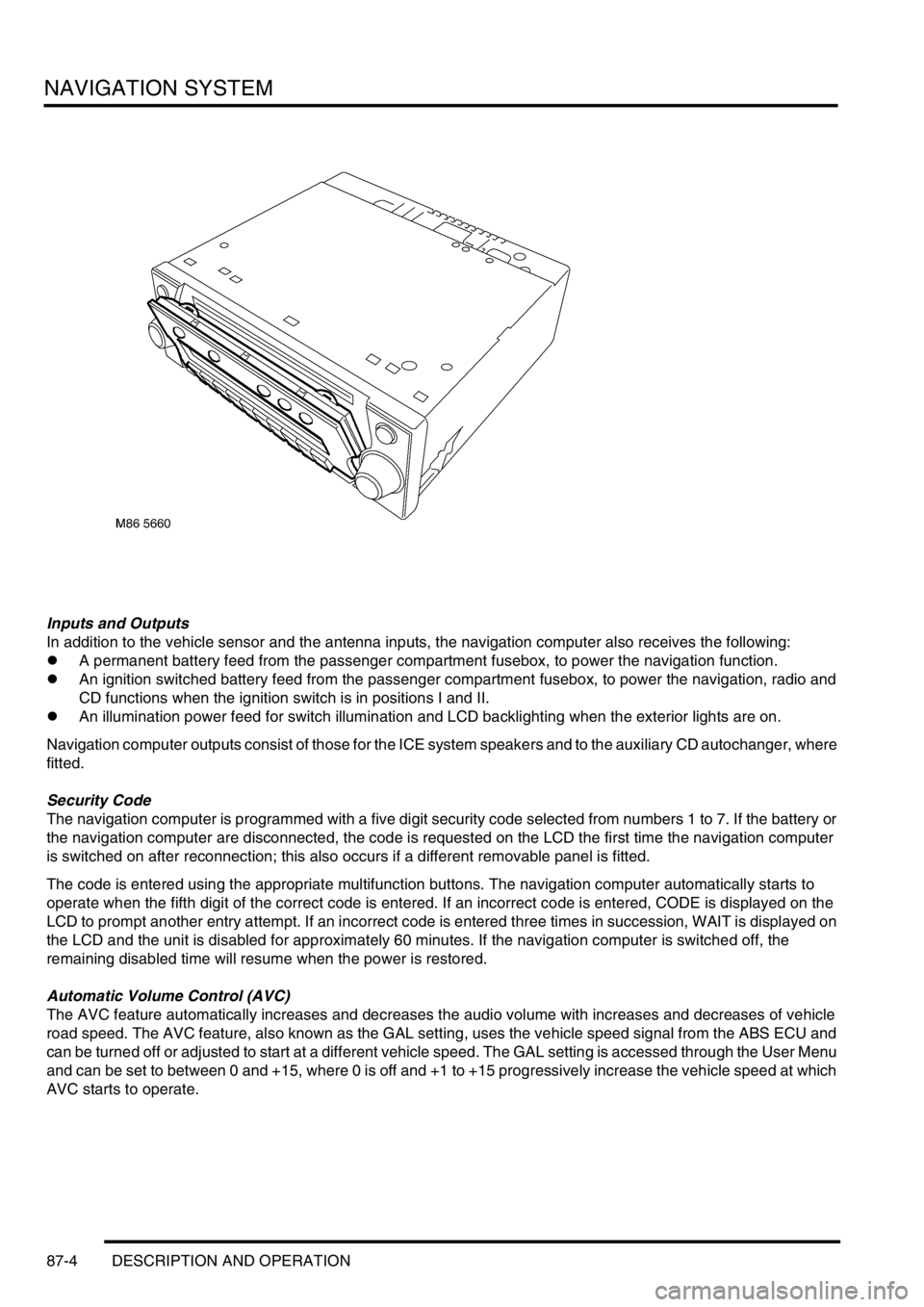
In addition to the vehicle sensor and the antenna inputs, the navigation computer also receives the following:
lA permanent battery feed from the passenger compartment fusebox, to power the navigation function.
lAn ignition switched battery feed from the passenger compartment fusebox, to power the navigation, radio and
CD functions when the ignition switch is in positions I and II.
lAn illumination power feed for switch illumination and LCD backlighting when the exterior lights are on.
Navigation computer outputs consist of those for the ICE system speakers and to the auxiliary CD autochanger, where
fitted.
Security Code
The navigation computer is programmed with a five digit security code selected from numbers 1 to 7. If the battery or
the navigation computer are disconnected, the code is requested on the LCD the first time the navigation computer
is switched on after reconnection; this also occurs if a different removable panel is fitted.
The code is entered using the appropriate multifunction buttons. The navigation computer automatically starts to
operate when the fifth digit of the correct code is entered. If an incorrect code is entered, CODE is displayed on the
LCD to prompt another entry attempt. If an incorrect code is entered three times in succession, WAIT is displayed on
the LCD and the unit is disabled for approximately 60 minutes. If the navigation computer is switched off, the
remaining disabled time will resume when the power is restored.
Automatic Volume Control (AVC)
The AVC feature automatically increases and decreases the audio volume with increases and decreases of vehicle
road speed. The AVC feature, also known as the GAL setting, uses the vehicle speed signal from the ABS ECU and
can be turned off or adjusted to start at a different vehicle speed. The GAL setting is accessed through the User Menu
and can be set to between 0 and +15, where 0 is off and +1 to +15 progressively increase the vehicle speed at which
AVC starts to operate.
Page 1622 of 1672
NAVIGATION SYSTEM
DESCRIPTION AND OPERATION 87-7
Sensor Check
1Call up the SENSORS screen on the LCD:
lIf the navigation CD-ROM has not been installed before, press and hold multifunction button 1 then press
multifunction button 10.
lIf the navigation CD-ROM has been installed before, use the garage menu as detailed above.
2Drive the vehicle forwards a short distance at a speed greater than 2.5 mph (4 km/h) and ensure the road speed
counter on the SENSORS screen starts to increment.
3Select reverse gear and ensure the direction arrows on the SENSORS screen point rearwards.
4Ensure the GPS data on the SENSORS screen is displayed and updated.
NOTE: The GPS data will randomly display a GPS MODULE FAILURE message. This is not a fault condition, and
no action need be taken, provided the GPS data switches between the GPS MODULE FAILURE message and
actual GPS data.
5Exit the SENSORS screen:
lIf the navigation CD-ROM has not been installed before, press and hold multifunction button 1 then press
multifunction button 10.
lIf the navigation CD-ROM has been installed before, press the Nav button.
Calibration Routine
1Park the vehicle outside in an area clear of high buildings, trees etc.
NOTE: The more open the surrounding area is, the faster the system will acquire sufficient GPS satellite signals to
begin calibration. To minimise the calibration time, the vehicle should not be moved again until the calibration
ride.
2Turn the ignition switch to position II. If the navigation computer does not come on, press the navigation
computer ON button.
3If necessary, use the navigation computer multifunction buttons to enter the security code.
4Turn the ignition switch to position 0 and remove the ignition key.
5Press the navigation computer ON button.
6Call up the SENSORS screen on the LCD:
lIf the navigation CD-ROM has not been installed before, press and hold multifunction button 1 then press
multifunction button 10.
lIf the navigation CD-ROM has been installed before, use the garage menu as detailed above.
7Turn the LH rotary control to minimum volume.
8Wait for 30 minutes. If necessary, the vehicle can be left unattended and locked.
NOTE: Land Rover recommend a minimum of 30 minutes be allowed to elapse in order to ensure that only a short
distance need be driven to achieve calibration.
9After the 30 minutes have elapsed, ensure the navigation computer LCD shows a GPS almanac figure of 27 or
higher.
10Start the vehicle engine and allow to idle.
11Install the navigation CD-ROM.
12Wait until the navigation computer LCD prompts for a language to be selected. Turn the RH rotary control to
scroll through the options, highlight the required language and press the RH rotary control to select.
13The navigation computer LCD will prompt for a voice to be selected. Turn the RH rotary control to scroll through
the options, highlight the required voice and press the RH rotary control to select.
14Wait until the navigation computer LCD advises "language has been loaded OK". Press the RH rotary control to
confirm the language and voice selections.
15The navigation computer LCD will default to the CALIBRATION RIDE screen and should show the
CALIBRATION RIDE CAN START message. The GPS data and the road speed counter will also be shown.
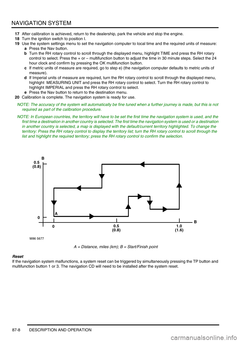
16Drive the vehicle over a road route approximating that shown below (it is not necessary to copy the route
exactly). Calibration is complete when the navigation computer LCD switches to show DESTINATION & POI
and the satellite graphic. If all the pre calibration ride conditions were complied with, calibration is typically
achieved within 3 miles (5 km) and usually occurs when the vehicle returns to the start point. However,
calibration may be achieved earlier in the journey and, if it is, there is no need to complete the remainder of the
calibration route.
Page 1623 of 1672
NAVIGATION SYSTEM
87-8 DESCRIPTION AND OPERATION
17After calibration is achieved, return to the dealership, park the vehicle and stop the engine.
18Turn the ignition switch to position I.
19Use the system settings menu to set the navigation computer to local time and the required units of measure:
aPress the Nav button.
bTurn the RH rotary control to scroll through the displayed menu, highlight TIME and press the RH rotary
control to select. Press the + or – multifunction button to adjust the time in 30 minute steps. Select the 24
hour clock and confirm by pressing the OK multifunction button.
cIf metric units of measure are required, go to step e) (the navigation computer defaults to metric units of
measure).
dIf Imperial units of measure are required, turn the RH rotary control to scroll through the displayed menu,
highlight MEASURING UNIT and press the RH rotary control to select. Turn the RH rotary control to
highlight IMPERIAL and press the RH rotary control to select.
ePress the Nav button to return to the destination menu.
20Calibration is complete. The navigation system is ready for use.
NOTE: The accuracy of the system will automatically be fine tuned when a further journey is made, but this is not
required as part of the calibration procedure.
NOTE: In European countries, the territory will have to be set the first time the navigation system is used, and the
first time a destination in another country is selected. The first time the navigation system is used or a destination
in another country is selected, a map is displayed with the default/current territory highlighted. To change the
territory: Press the RH rotary control to display the territory list; turn the RH rotary control to scroll through the
list and highlight the required territory; press the RH rotary control to confirm the selection.
A = Distance, miles (km); B = Start/Finish point
Reset
If the navigation system malfunctions, a system reset can be triggered by simultaneously pressing the TP button and
multifunction button 1 or 3. The navigation CD will need to be installed after the system reset.
Page 1635 of 1672
INSTRUMENTS
88-8 DESCRIPTION AND OPERATION
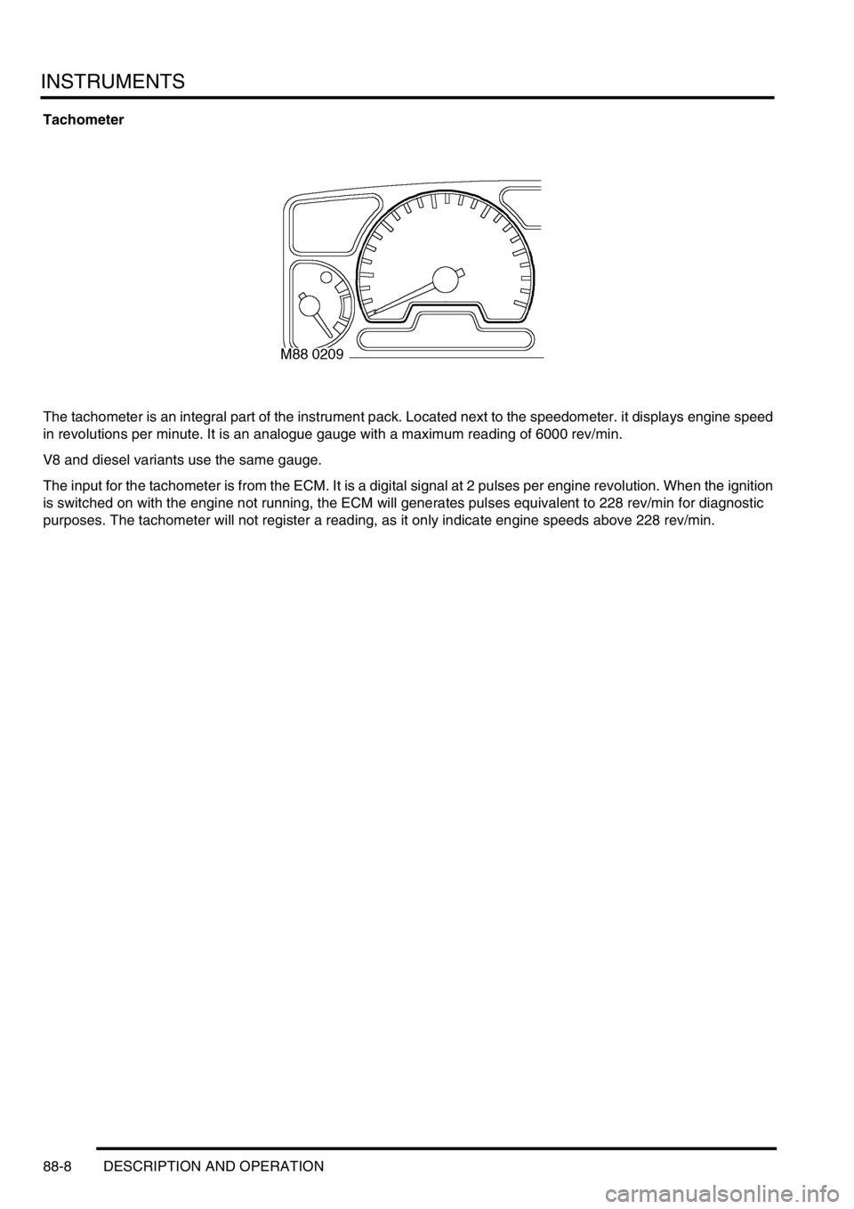
Tachometer
The tachometer is an integral part of the instrument pack. Located next to the speedometer. it displays engine speed
in revolutions per minute. It is an analogue gauge with a maximum reading of 6000 rev/min.
V8 and diesel variants use the same gauge.
The input for the tachometer is from the ECM. It is a digital signal at 2 pulses per engine revolution. When the ignition
is switched on with the engine not running, the ECM will generates pulses equivalent to 228 rev/min for diagnostic
purposes. The tachometer will not register a reading, as it only indicate engine speeds above 228 rev/min.
Page 1636 of 1672
INSTRUMENTS
DESCRIPTION AND OPERATION 88-9
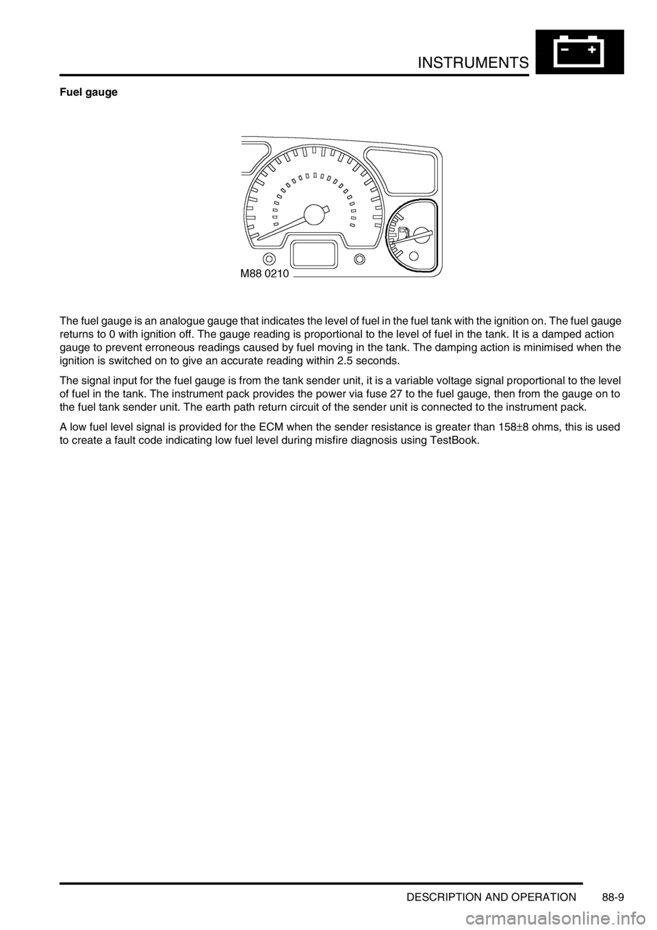
Fuel gauge
The fuel gauge is an analogue gauge that indicates the level of fuel in the fuel tank with the ignition on. The fuel gauge
returns to 0 with ignition off. The gauge reading is proportional to the level of fuel in the tank. It is a damped action
gauge to prevent erroneous readings caused by fuel moving in the tank. The damping action is minimised when the
ignition is switched on to give an accurate reading within 2.5 seconds.
The signal input for the fuel gauge is from the tank sender unit, it is a variable voltage signal proportional to the level
of fuel in the tank. The instrument pack provides the power via fuse 27 to the fuel gauge, then from the gauge on to
the fuel tank sender unit. The earth path return circuit of the sender unit is connected to the instrument pack.
A low fuel level signal is provided for the ECM when the sender resistance is greater than 158
±8 ohms, this is used
to create a fault code indicating low fuel level during misfire diagnosis using TestBook.
Page 1639 of 1672
INSTRUMENTS
88-12 DESCRIPTION AND OPERATION
Malfunction Indicator Lamp (MIL)/ SERVICE ENGINE SOON warning lamp
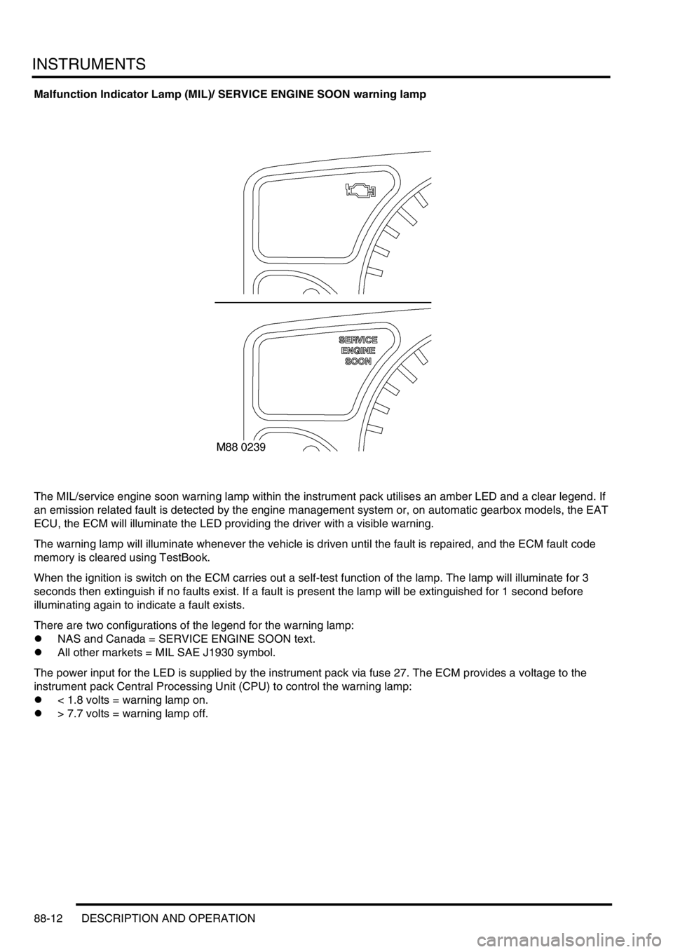
The MIL/service engine soon warning lamp within the instrument pack utilises an amber LED and a clear legend. If
an emission related fault is detected by the engine management system or, on automatic gearbox models, the EAT
ECU, the ECM will illuminate the LED providing the driver with a visible warning.
The warning lamp will illuminate whenever the vehicle is driven until the fault is repaired, and the ECM fault code
memory is cleared using TestBook.
When the ignition is switch on the ECM carries out a self-test function of the lamp. The lamp will illuminate for 3
seconds then extinguish if no faults exist. If a fault is present the lamp will be extinguished for 1 second before
illuminating again to indicate a fault exists.
There are two configurations of the legend for the warning lamp:
lNAS and Canada = SERVICE ENGINE SOON text.
lAll other markets = MIL SAE J1930 symbol.
The power input for the LED is supplied by the instrument pack via fuse 27. The ECM provides a voltage to the
instrument pack Central Processing Unit (CPU) to control the warning lamp:
l< 1.8 volts = warning lamp on.
l> 7.7 volts = warning lamp off.