2002 LAND ROVER DISCOVERY radio
[x] Cancel search: radioPage 1165 of 1672
INTERIOR TRIM COMPONENTS
76-3-12 REPAIRS
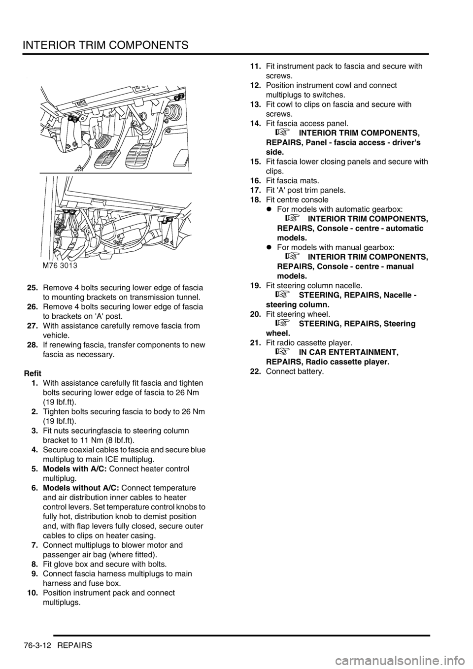
25.Remove 4 bolts securing lower edge of fascia
to mounting brackets on transmission tunnel.
26.Remove 4 bolts securing lower edge of fascia
to brackets on 'A' post.
27.With assistance carefully remove fascia from
vehicle.
28.If renewing fascia, transfer components to new
fascia as necessary.
Refit
1.With assistance carefully fit fascia and tighten
bolts securing lower edge of fascia to 26 Nm
(19 lbf.ft).
2.Tighten bolts securing fascia to body to 26 Nm
(19 lbf.ft).
3.Fit nuts securingfascia to steering column
bracket to 11 Nm (8 lbf.ft).
4.Secure coaxial cables to fascia and secure blue
multiplug to main ICE multiplug.
5. Models with A/C: Connect heater control
multiplug.
6. Models without A/C: Connect temperature
and air distribution inner cables to heater
control levers. Set temperature control knobs to
fully hot, distribution knob to demist position
and, with flap levers fully closed, secure outer
cables to clips on heater casing.
7.Connect multiplugs to blower motor and
passenger air bag (where fitted).
8.Fit glove box and secure with bolts.
9.Connect fascia harness multiplugs to main
harness and fuse box.
10.Position instrument pack and connect
multiplugs.11.Fit instrument pack to fascia and secure with
screws.
12.Position instrument cowl and connect
multiplugs to switches.
13.Fit cowl to clips on fascia and secure with
screws.
14.Fit fascia access panel.
+ INTERIOR TRIM COMPONENTS,
REPAIRS, Panel - fascia access - driver's
side.
15.Fit fascia lower closing panels and secure with
clips.
16.Fit fascia mats.
17.Fit 'A' post trim panels.
18.Fit centre console
lFor models with automatic gearbox:
+ INTERIOR TRIM COMPONENTS,
REPAIRS, Console - centre - automatic
models.
lFor models with manual gearbox:
+ INTERIOR TRIM COMPONENTS,
REPAIRS, Console - centre - manual
models.
19.Fit steering column nacelle.
+ STEERING, REPAIRS, Nacelle -
steering column.
20.Fit steering wheel.
+ STEERING, REPAIRS, Steering
wheel.
21.Fit radio cassette player.
+ IN CAR ENTERTAINMENT,
REPAIRS, Radio cassette player.
22.Connect battery.
Page 1168 of 1672
INTERIOR TRIM COMPONENTS
REPAIRS 76-3-15
Louvre panel assembly - centre fascia
$% 76.46.42
Remove
1.Remove radio cassette player from fascia.
+ IN CAR ENTERTAINMENT,
REPAIRS, Radio cassette player.
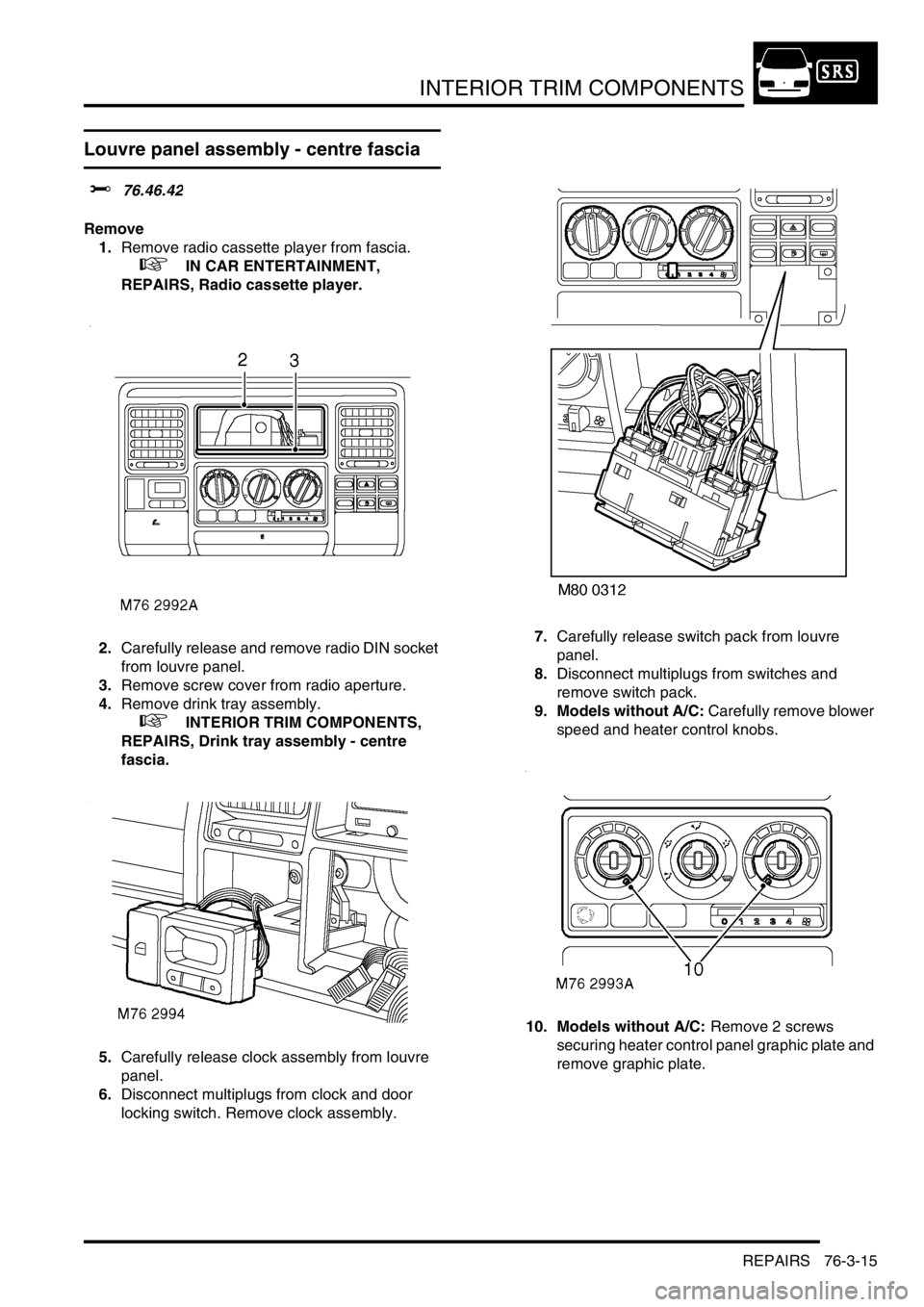
2.Carefully release and remove radio DIN socket
from louvre panel.
3.Remove screw cover from radio aperture.
4.Remove drink tray assembly.
+ INTERIOR TRIM COMPONENTS,
REPAIRS, Drink tray assembly - centre
fascia.
5.Carefully release clock assembly from louvre
panel.
6.Disconnect multiplugs from clock and door
locking switch. Remove clock assembly.7.Carefully release switch pack from louvre
panel.
8.Disconnect multiplugs from switches and
remove switch pack.
9. Models without A/C: Carefully remove blower
speed and heater control knobs.
10. Models without A/C: Remove 2 screws
securing heater control panel graphic plate and
remove graphic plate.
Page 1170 of 1672
INTERIOR TRIM COMPONENTS
REPAIRS 76-3-17
9.Fit drinks tray.
+ INTERIOR TRIM COMPONENTS,
REPAIRS, Drink tray assembly - centre
fascia.
10.Fit and secure radio DIN socket.
11.Fit screw cover to radio aperture.
12.Fit radio cassette player.
+ IN CAR ENTERTAINMENT,
REPAIRS, Radio cassette player.
Carpet - front
$% 76.49.02
Remove
1. Models with premium ICE: Remove power
amplifier.
+ IN CAR ENTERTAINMENT,
REPAIRS, Amplifier - power.
2. Models with premium ICE: Remove CD
autochanger.
+ IN CAR ENTERTAINMENT,
REPAIRS, CD autochanger.
3.Remove centre console.
lFor models with manual gearbox:
+ INTERIOR TRIM COMPONENTS,
REPAIRS, Console - centre - manual
models.
lFor models with automatic gearbox:
+ INTERIOR TRIM COMPONENTS,
REPAIRS, Console - centre - automatic
models.
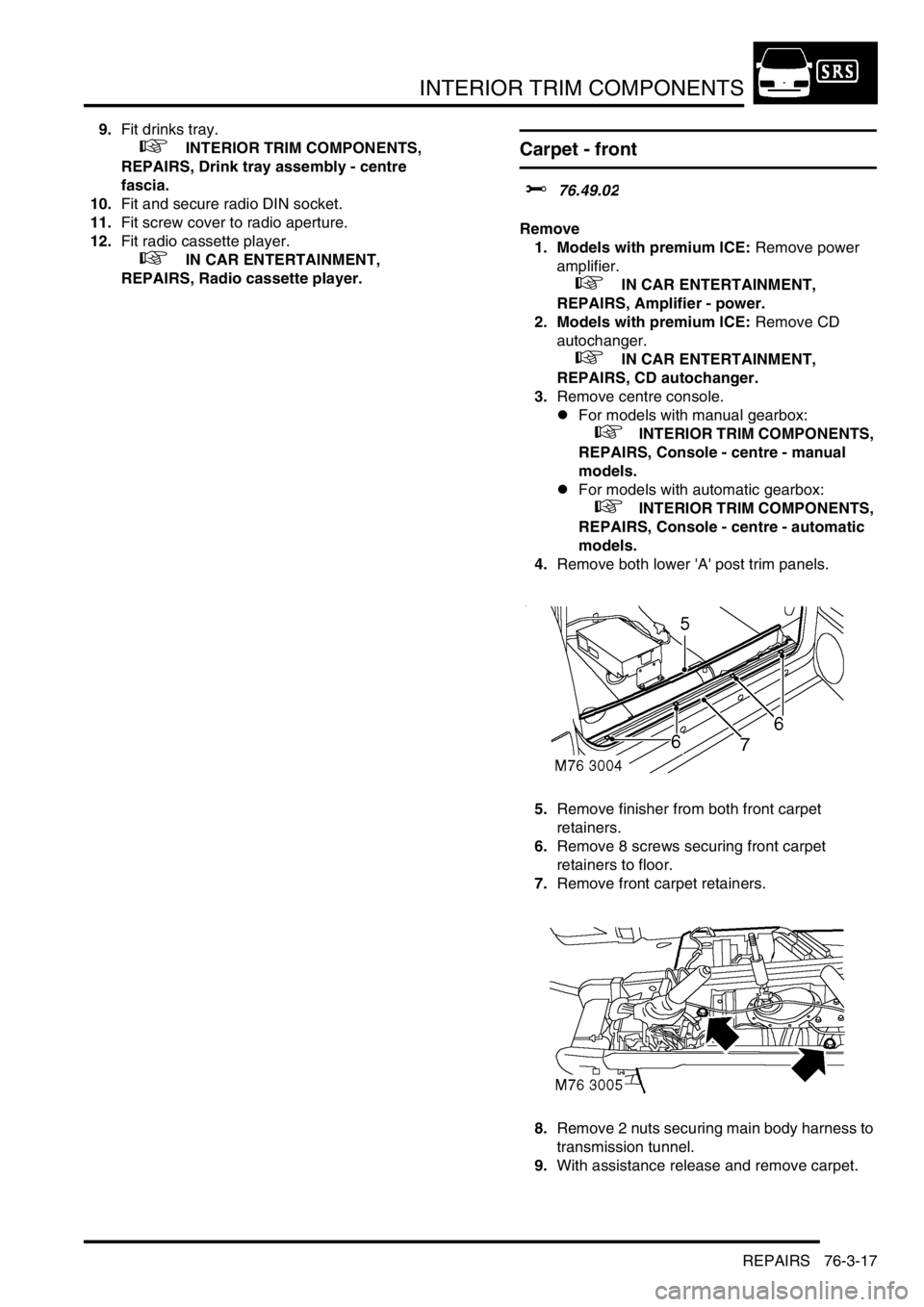
4.Remove both lower 'A' post trim panels.
5.Remove finisher from both front carpet
retainers.
6.Remove 8 screws securing front carpet
retainers to floor.
7.Remove front carpet retainers.
8.Remove 2 nuts securing main body harness to
transmission tunnel.
9.With assistance release and remove carpet.
Page 1349 of 1672
HEATING AND VENTILATION
80-8DESCRIPTION AND OPERATION
Control panel
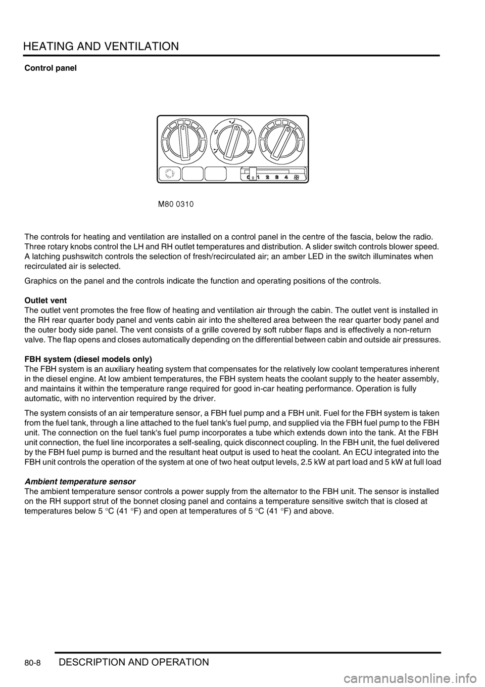
The controls for heating and ventilation are installed on a control panel in the centre of the fascia, below the radio.
Three rotary knobs control the LH and RH outlet temperatures and distribution. A slider switch controls blower speed.
A latching pushswitch controls the selection of fresh/recirculated air; an amber LED in the switch illuminates when
recirculated air is selected.
Graphics on the panel and the controls indicate the function and operating positions of the controls.
Outlet vent
The outlet vent promotes the free flow of heating and ventilation air through the cabin. The outlet vent is installed in
the RH rear quarter body panel and vents cabin air into the sheltered area between the rear quarter body panel and
the outer body side panel. The vent consists of a grille covered by soft rubber flaps and is effectively a non-return
valve. The flap opens and closes automatically depending on the differential between cabin and outside air pressures.
FBH system (diesel models only)
The FBH system is an auxiliary heating system that compensates for the relatively low coolant temperatures inherent
in the diesel engine. At low ambient temperatures, the FBH system heats the coolant supply to the heater assembly,
and maintains it within the temperature range required for good in-car heating performance. Operation is fully
automatic, with no intervention required by the driver.
The system consists of an air temperature sensor, a FBH fuel pump and a FBH unit. Fuel for the FBH system is taken
from the fuel tank, through a line attached to the fuel tank's fuel pump, and supplied via the FBH fuel pump to the FBH
unit. The connection on the fuel tank's fuel pump incorporates a tube which extends down into the tank. At the FBH
unit connection, the fuel line incorporates a self-sealing, quick disconnect coupling. In the FBH unit, the fuel delivered
by the FBH fuel pump is burned and the resultant heat output is used to heat the coolant. An ECU integrated into the
FBH unit controls the operation of the system at one of two heat output levels, 2.5 kW at part load and 5 kW at full load
Ambient temperature sensor
The ambient temperature sensor controls a power supply from the alternator to the FBH unit. The sensor is installed
on the RH support strut of the bonnet closing panel and contains a temperature sensitive switch that is closed at
temperatures below 5
°C (41 °F) and open at temperatures of 5 °C (41 °F) and above.
Page 1363 of 1672
HEATING AND VENTILATION
80-22REPAIRS
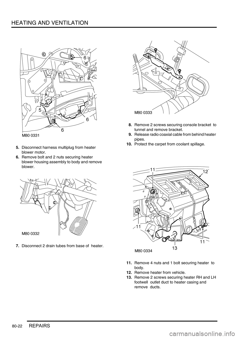
5.Disconnect harness multiplug from heater
blower motor.
6.Remove bolt and 2 nuts securing heater
blower housing assembly to body and remove
blower.
7.Disconnect 2 drain tubes from base of heater. 8.Remove 2 screws securing console bracket to
tunnel and remove bracket.
9.Release radio coaxial cable from behind heater
pipes.
10.Protect the carpet from coolant spillage.
11.Remove 4 nuts and 1 bolt securing heater to
body.
12.Remove heater from vehicle.
13.Remove 2 screws securing heater RH and LH
footwell outlet duct to heater casing and
remove ducts.
Page 1364 of 1672
HEATING AND VENTILATION
REPAIRS 80-23
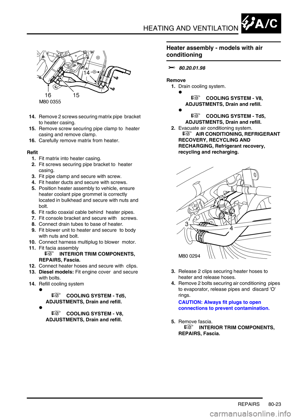
14.Remove 2 screws securing matrix pipe bracket
to heater casing.
15.Remove screw securing pipe clamp to heater
casing and remove clamp.
16.Carefully remove matrix from heater.
Refit
1.Fit matrix into heater casing.
2.Fit screws securing pipe bracket to heater
casing.
3.Fit pipe clamp and secure with screw.
4.Fit heater ducts and secure with screws.
5.Position heater assembly to vehicle, ensure
heater coolant pipe grommet is correctly
located in bulkhead and secure with nuts and
bolt.
6.Fit radio coaxial cable behind heater pipes.
7.Fit console bracket and secure with screws.
8.Connect drain tubes to base of heater.
9.Fit blower unit to heater and secure to body
with nuts and bolt.
10.Connect harness multiplug to blower motor.
11.Fit facia assembly
+ INTERIOR TRIM COMPONENTS,
REPAIRS, Fascia.
12.Connect heater hoses and secure with clips.
13. Diesel models: Fit engine cover and secure
with bolts.
14.Refill cooling system
l
+ COOLING SYSTEM - Td5,
ADJUSTMENTS, Drain and refill.
l
+ COOLING SYSTEM - V8,
ADJUSTMENTS, Drain and refill.
Heater assembly - models with air
conditioning
$% 80.20.01.98
Remove
1.Drain cooling system.
l
+ COOLING SYSTEM - V8,
ADJUSTMENTS, Drain and refill.
l
+ COOLING SYSTEM - Td5,
ADJUSTMENTS, Drain and refill.
2.Evacuate air conditioning system.
+ AIR CONDITIONING, REFRIGERANT
RECOVERY, RECYCLING AND
RECHARGING, Refrigerant recovery,
recycling and recharging.
3.Release 2 clips securing heater hoses to
heater and release hoses.
4.Remove 2 bolts securing air conditioning pipes
to evaporator, release pipes and discard 'O'
rings.
CAUTION: Always fit plugs to open
connections to prevent contamination.
5.Remove fascia.
+ INTERIOR TRIM COMPONENTS,
REPAIRS, Fascia.
Page 1385 of 1672
AIR CONDITIONING
82-12DESCRIPTION AND OPERATION
Control system
The control system operates the refrigerant system and the control flaps in the heater assembly to control the
temperature and distribution of air in the vehicle interior. It also outputs signals to the fresh/recirculated air servo motor
and the blower to control the volume and source of inlet air. The control system consists of:
lAn Air Temperature Control (ATC) ECU.
lA dual pressure switch.
lAn evaporator temperature sensor.
lAn in-car temperature sensor.
lA sunlight sensor.
lA heater coolant temperature sensor.
lAn ambient temperature sensor.
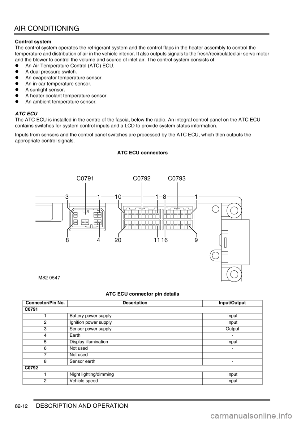
ATC ECU
The ATC ECU is installed in the centre of the fascia, below the radio. An integral control panel on the ATC ECU
contains switches for system control inputs and a LCD to provide system status information.
Inputs from sensors and the control panel switches are processed by the ATC ECU, which then outputs the
appropriate control signals.
ATC ECU connectors
ATC ECU connector pin details
Connector/Pin No. Description Input/Output
C0791
1 Battery power supply Input
2 Ignition power supply Input
3 Sensor power supply Output
4Earth-
5 Display illumination Input
6 Not used-
7 Not used-
8 Sensor earth -
C0792
1 Night lighting/dimming Input
2 Vehicle speed Input
Page 1410 of 1672
AIR CONDITIONING
REPAIRS 82-37
12.Remove receiver drier from mounting bracket.
13.Remove dual pressure switch from receiver
drier
Refit
1.Fit dual pressure switch to receiver drier and
tighten to 10 Nm (7 lbf.ft).
2.Fit receiver drier to mounting bracket and
tighten clamping bolt.
3.Fit receiver drier assembly to condenser.
4.Fit bolts securing receiver drier mounting
bracket to condenser and tighten to 5 Nm (3.7
lbf.ft).
5.Remove caps from air conditioning pipes and
receiver drier.
6.Remove old 'O' rings from pipes.
7.Fit new 'O' rings to pipes and lubricate with
refrigerant oil.
8.Connect air conditioning pipes to receiver
drier.
9.Fit bolts securing air conditioning pipes to
receiver drier and tighten to 5 Nm (3.7 lbf.ft).
10.Connect multiplug to dual pressure switch.
11.Fit front grille.
+ EXTERIOR FITTINGS, REPAIRS,
Grille - front - up to 03MY.
12.Recharge air conditioning system.
+ AIR CONDITIONING, REFRIGERANT
RECOVERY, RECYCLING AND
RECHARGING, Refrigerant recovery,
recycling and recharging.
ECU - air temperature control
$% 82.20.90
Remove
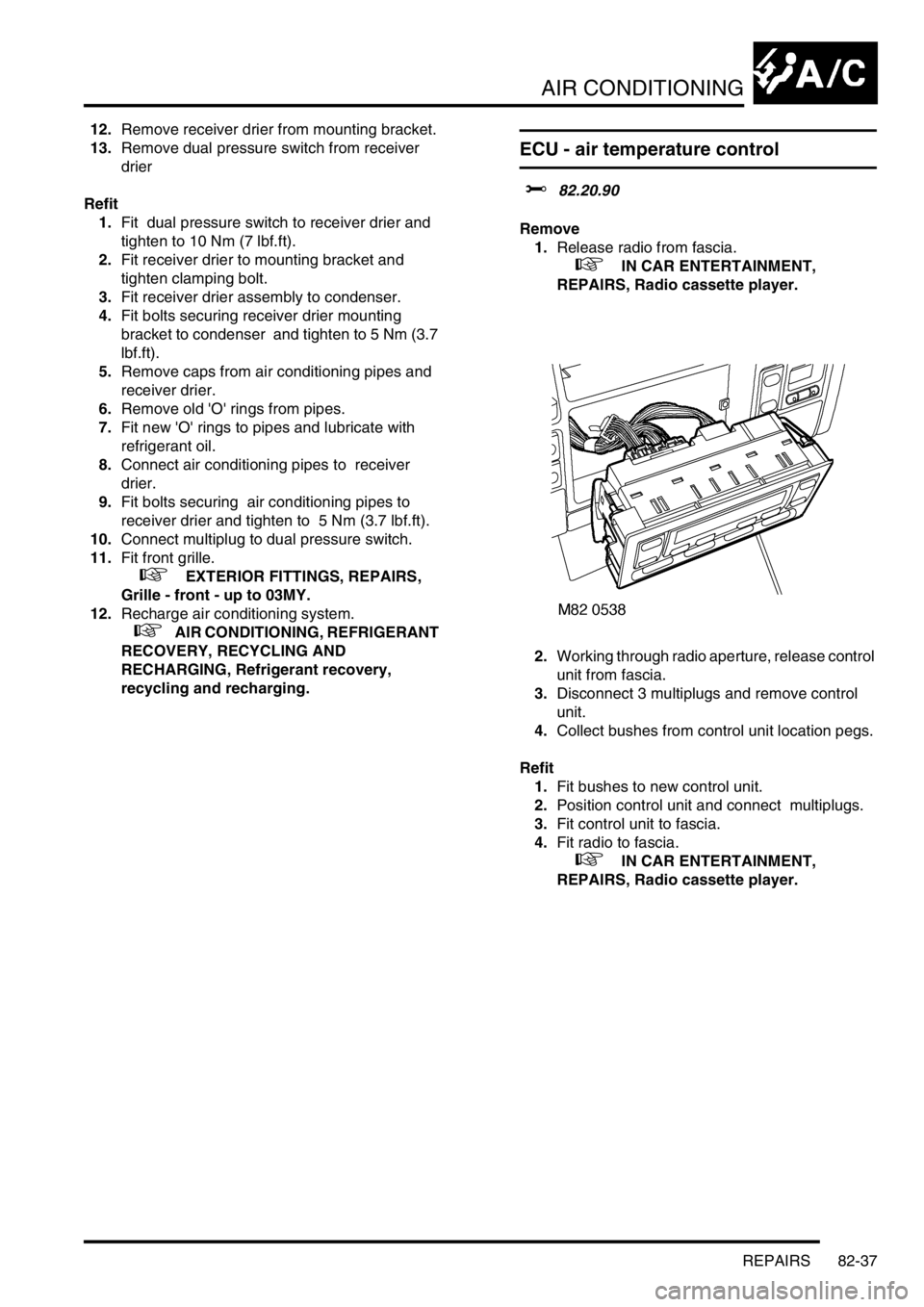
1.Release radio from fascia.
+ IN CAR ENTERTAINMENT,
REPAIRS, Radio cassette player.
2.Working through radio aperture, release control
unit from fascia.
3.Disconnect 3 multiplugs and remove control
unit.
4.Collect bushes from control unit location pegs.
Refit
1.Fit bushes to new control unit.
2.Position control unit and connect multiplugs.
3.Fit control unit to fascia.
4.Fit radio to fascia.
+ IN CAR ENTERTAINMENT,
REPAIRS, Radio cassette player.