Page 1043 of 1672

REAR SUSPENSION
64-38 REPAIRS
Bushes - rear long arm - ACE
$% 64.60.46
CAUTION: The ACE hydraulic system is
extremely sensitive to the ingress of dirt or
debris. The smallest amount could render the
system unserviceable. It is imperative that the
following precautions are taken.
lACE components are thoroughly cleaned
externally before work commences;
lall opened pipe and module ports are
capped immediately;
lall fluid is stored in and administered
through clean containers.
Models with SLS:
WARNING: Ensure the air suspension system is
made safe before commencing work. Otherwise
the chassis may lower onto the bump stops
during repair.
Remove
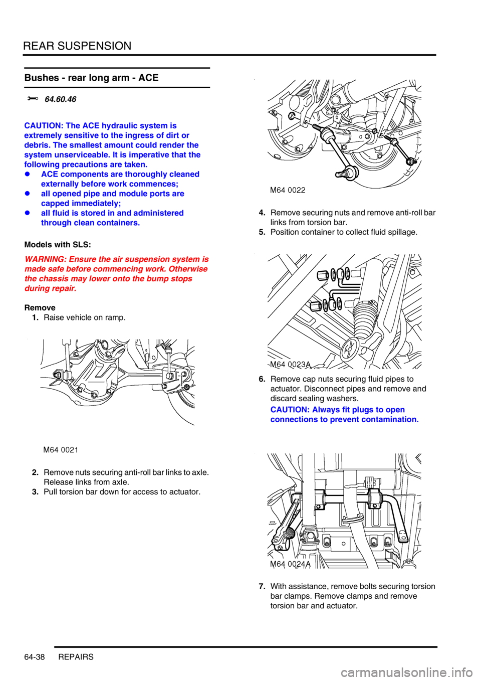
1.Raise vehicle on ramp.
2.Remove nuts securing anti-roll bar links to axle.
Release links from axle.
3.Pull torsion bar down for access to actuator.4.Remove securing nuts and remove anti-roll bar
links from torsion bar.
5.Position container to collect fluid spillage.
6.Remove cap nuts securing fluid pipes to
actuator. Disconnect pipes and remove and
discard sealing washers.
CAUTION: Always fit plugs to open
connections to prevent contamination.
7.With assistance, remove bolts securing torsion
bar clamps. Remove clamps and remove
torsion bar and actuator.
Page 1044 of 1672
REAR SUSPENSION
REPAIRS 64-39
8.Use LRT-60-009 to remove nut securing
actuator push rod to long arm.
9.Remove nut and bolt securing actuator to short
arm and remove actuator.
10.Restrain torsion bar and remove long arm
securing bolt and washer. Remove long arm
from torsion bar.
CAUTION: The short arm and torsion bar
are supplied as an assembly and must not
be separated.11.Use a suitable drift to remove both halves of
slipper bush from long arm.
12.Use suitable adaptors to press actuator rod end
bush from long arm.
Page 1045 of 1672

REAR SUSPENSION
64-40 REPAIRS
Refit
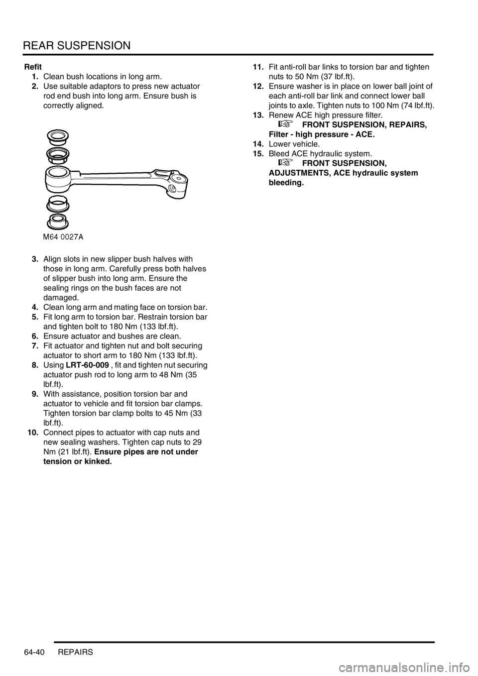
1.Clean bush locations in long arm.
2.Use suitable adaptors to press new actuator
rod end bush into long arm. Ensure bush is
correctly aligned.
3.Align slots in new slipper bush halves with
those in long arm. Carefully press both halves
of slipper bush into long arm. Ensure the
sealing rings on the bush faces are not
damaged.
4.Clean long arm and mating face on torsion bar.
5.Fit long arm to torsion bar. Restrain torsion bar
and tighten bolt to 180 Nm (133 lbf.ft).
6.Ensure actuator and bushes are clean.
7.Fit actuator and tighten nut and bolt securing
actuator to short arm to 180 Nm (133 lbf.ft).
8.Using LRT-60-009 , fit and tighten nut securing
actuator push rod to long arm to 48 Nm (35
lbf.ft).
9.With assistance, position torsion bar and
actuator to vehicle and fit torsion bar clamps.
Tighten torsion bar clamp bolts to 45 Nm (33
lbf.ft).
10.Connect pipes to actuator with cap nuts and
new sealing washers. Tighten cap nuts to 29
Nm (21 lbf.ft). Ensure pipes are not under
tension or kinked.11.Fit anti-roll bar links to torsion bar and tighten
nuts to 50 Nm (37 lbf.ft).
12.Ensure washer is in place on lower ball joint of
each anti-roll bar link and connect lower ball
joints to axle. Tighten nuts to 100 Nm (74 lbf.ft).
13.Renew ACE high pressure filter.
+ FRONT SUSPENSION, REPAIRS,
Filter - high pressure - ACE.
14.Lower vehicle.
15.Bleed ACE hydraulic system.
+ FRONT SUSPENSION,
ADJUSTMENTS, ACE hydraulic system
bleeding.
Page 1063 of 1672

BRAKES
70-18 DESCRIPTION AND OPERATION
The SLABS ECU continually calculates vehicle speed using the wheel speed inputs from all four ABS sensors. The
calculated vehicle speed is then used as a reference against which individual wheel speeds are monitored for
unacceptable acceleration or deceleration. The ABS sensor inputs are also used by the SLABS ECU to detect vehicle
deceleration rate, vehicle cornering rate and rough terrain.
The engaged forward gear and (on manual gearbox models) the clutch status are computed from the engine data
input, the engine speed input and vehicle speed. Reverse gear status is provided by an input from the reverse lamp
switch (manual gearbox models) or the BCU (automatic gearbox models). On automatic models, the BCU also
provides the neutral selected input.
In addition to controlling the brake related functions, the SLABS ECU:
lControls the operation of the self levelling suspension (SLS) system (where fitted).
+ REAR SUSPENSION, DESCRIPTION AND OPERATION, Description.
lOn V8 models, outputs a rough road signal to the ECM when traversing rough terrain.
lOutputs a vehicle speed signal.
The vehicle speed signal is output to the following systems (where fitted):
lActive Cornering Enhancement.
+ FRONT SUSPENSION, DESCRIPTION AND OPERATION, Description - ACE.
lAir conditioning.
+ AIR CONDITIONING, DESCRIPTION AND OPERATION, Description.
lCruise control.
+ ENGINE MANAGEMENT SYSTEM - Td5, DESCRIPTION AND OPERATION, Description.
+ ENGINE MANAGEMENT SYSTEM - V8, DESCRIPTION AND OPERATION, Description - engine
management.
lEngine management.
+ ENGINE MANAGEMENT SYSTEM - Td5, DESCRIPTION AND OPERATION, Description.
+ ENGINE MANAGEMENT SYSTEM - V8, DESCRIPTION AND OPERATION, Description - engine
management.
lIn-car entertainment.
+ IN CAR ENTERTAINMENT, DESCRIPTION AND OPERATION, Description.
lInstrument pack.
+ INSTRUMENTS, DESCRIPTION AND OPERATION, Description.
ABS sensors
The ABS sensors supply the SLABS ECU with a sinusoidal speed signal from each wheel. An inductive sensor,
installed in the hub bearing of each wheel, senses off a 60 tooth exciter ring integrated into the inner race of the hub
bearing. Each ABS sensor has a fly-lead connecting it to the vehicle wiring.
6 Shuttle valve switches Input
7 Rear left outlet solenoid valve Output
8 Rear left inlet solenoid valve Output
9 Centre differential lock switch Input
10 Rear right outlet solenoid valve Output
11 Rear right inlet solenoid valve Output
12 Brake lamp relay Output
15 Return pump relay Output
C0655
7 Audible warning Output
10 Engine speed Input
Connector and pins not listed are either not used or used by the self levelling suspension system.
+ REAR SUSPENSION, DESCRIPTION AND OPERATION, Description.
Connector/Pin No. Description Input/Output
Page 1091 of 1672
BRAKES
70-46 REPAIRS
6.Remove 4 nuts securing SLABS ECU and
remove ECU.
Refit
1.Fit new SLABS ECU to bracket and secure with
nuts.
2.Fit ECU's and bracket assembly to body and
secure with nuts.
3.Connect multiplugs to ACE ECU and SLABS
ECU.
4.Fit BCU.
+ BODY CONTROL UNIT, REPAIRS,
Body control unit (BCU).
5.Programme the new SLABS ECU using
TestBook.
Sensor – ABS – front
$% 70.65.30
ABS sensor is supplied fitted to wheel hub and
must not be removed.
Remove
1.Remove wheel hub.
+ FRONT SUSPENSION, REPAIRS,
Wheel hub.
Refit
1.Fit wheel hub.
+ FRONT SUSPENSION, REPAIRS,
Wheel hub.
Page 1092 of 1672
BRAKES
REPAIRS 70-47
Sensor – ABS – rear
$% 70.65.31
ABS sensor is supplied fitted to wheel hub and
must not be removed.
Remove
1.Remove wheel hub.
+ REAR SUSPENSION, REPAIRS,
Wheel hub.
Refit
1.Fit wheel hub.
+ REAR SUSPENSION, REPAIRS,
Wheel hub.
Modulator unit - ABS
$% 70.65.49
Remove
1.Position cloth under modulator to absorb fluid
spillage.
CAUTION: Brake fluid will damage paint
finished surfaces. If spilled, immediately
remove fluid and clean area with water.
2.Disconnect 3 multiplugs from ABS modulator.
3.Disconnect 2 inlet brake pipe unions from pump
side of modulator.
CAUTION: Always fit plugs to open
connections to prevent contamination.
4.Disconnect 4 outlet brake pipe unions from top
of modulator.
CAUTION: Always fit plugs to open
connections to prevent contamination.
5.Loosen 3 nuts securing modulator to mounting
bracket.
6.Release and remove modulator from mounting
bracket.
7.Remove 3 mounting rubbers from modulator.
Page 1277 of 1672

PANEL REPAIRS
77-2-28 REPAIRS
Repair
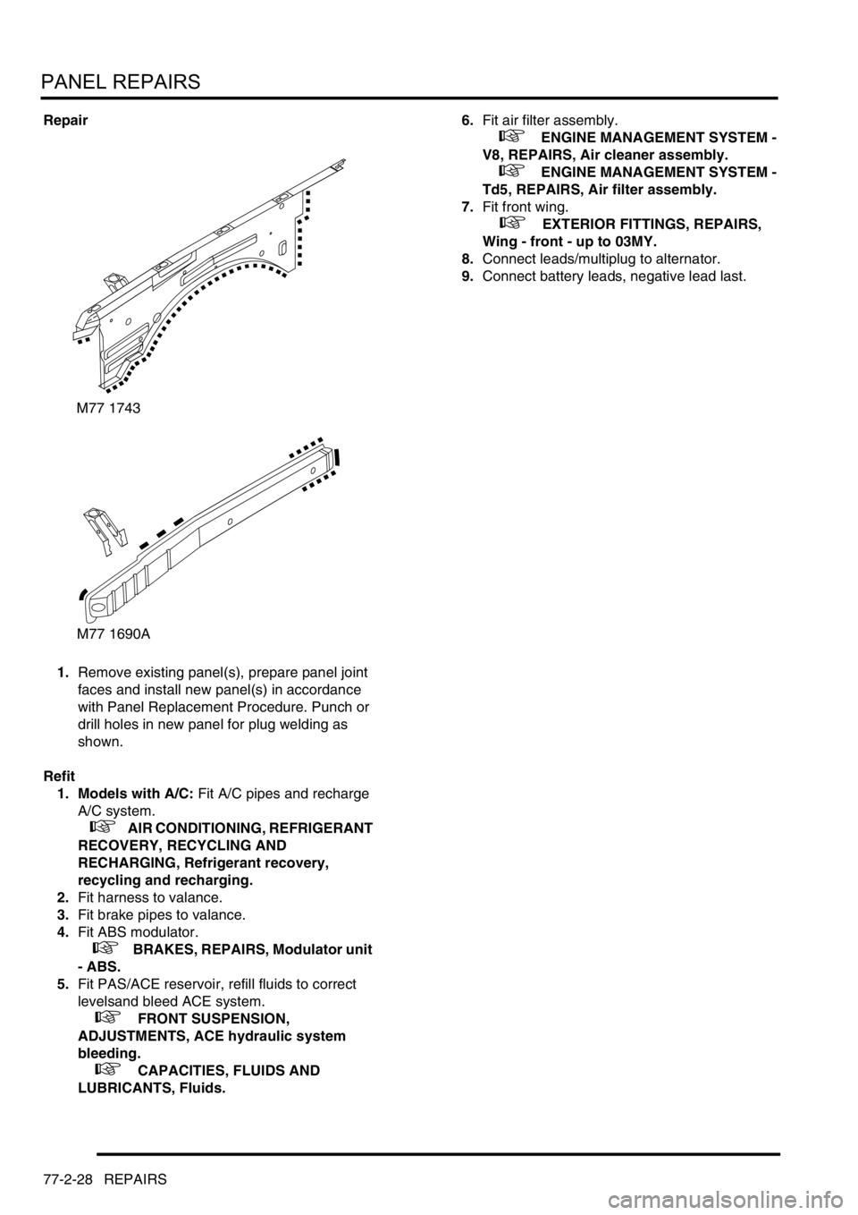
1.Remove existing panel(s), prepare panel joint
faces and install new panel(s) in accordance
with Panel Replacement Procedure. Punch or
drill holes in new panel for plug welding as
shown.
Refit
1. Models with A/C: Fit A/C pipes and recharge
A/C system.
+ AIR CONDITIONING, REFRIGERANT
RECOVERY, RECYCLING AND
RECHARGING, Refrigerant recovery,
recycling and recharging.
2.Fit harness to valance.
3.Fit brake pipes to valance.
4.Fit ABS modulator.
+ BRAKES, REPAIRS, Modulator unit
- ABS.
5.Fit PAS/ACE reservoir, refill fluids to correct
levelsand bleed ACE system.
+ FRONT SUSPENSION,
ADJUSTMENTS, ACE hydraulic system
bleeding.
+ CAPACITIES, FLUIDS AND
LUBRICANTS, Fluids.6.Fit air filter assembly.
+ ENGINE MANAGEMENT SYSTEM -
V8, REPAIRS, Air cleaner assembly.
+ ENGINE MANAGEMENT SYSTEM -
Td5, REPAIRS, Air filter assembly.
7.Fit front wing.
+ EXTERIOR FITTINGS, REPAIRS,
Wing - front - up to 03MY.
8.Connect leads/multiplug to alternator.
9.Connect battery leads, negative lead last.
M77 1743
M77 1690A
Page 1279 of 1672

PANEL REPAIRS
77-2-30 REPAIRS
Valance upper assembly (front section) -
LH
In this procedure, the front wing, the valance outer
reinforcement (front section) and the bonnet alarm
switch mounting bracket are replaced in conjunction
with the LH valance upper assembly (front section).
Remove
1.Disconnect both battery leads, negative lead
first.
2.Disconnect leads/multiplug from alternator.
3.Remove front wing.
+ EXTERIOR FITTINGS, REPAIRS,
Wing - front - up to 03MY.
4.Remove air filter assembly.
+ ENGINE MANAGEMENT SYSTEM -
Td5, REPAIRS, Air filter assembly.
+ ENGINE MANAGEMENT SYSTEM -
V8, REPAIRS, Air cleaner assembly.
5.Remove PAS/ACE reservoir.
6.Remove ABS modulator.
+ BRAKES, REPAIRS, Modulator unit
- ABS.
7.Release harness from valance and position
aside.
8. Models with A/C: Depressurise A/C system
and remove pipes from valance.
+ AIR CONDITIONING, REFRIGERANT
RECOVERY, RECYCLING AND
RECHARGING, Refrigerant recovery,
recycling and recharging.Repair
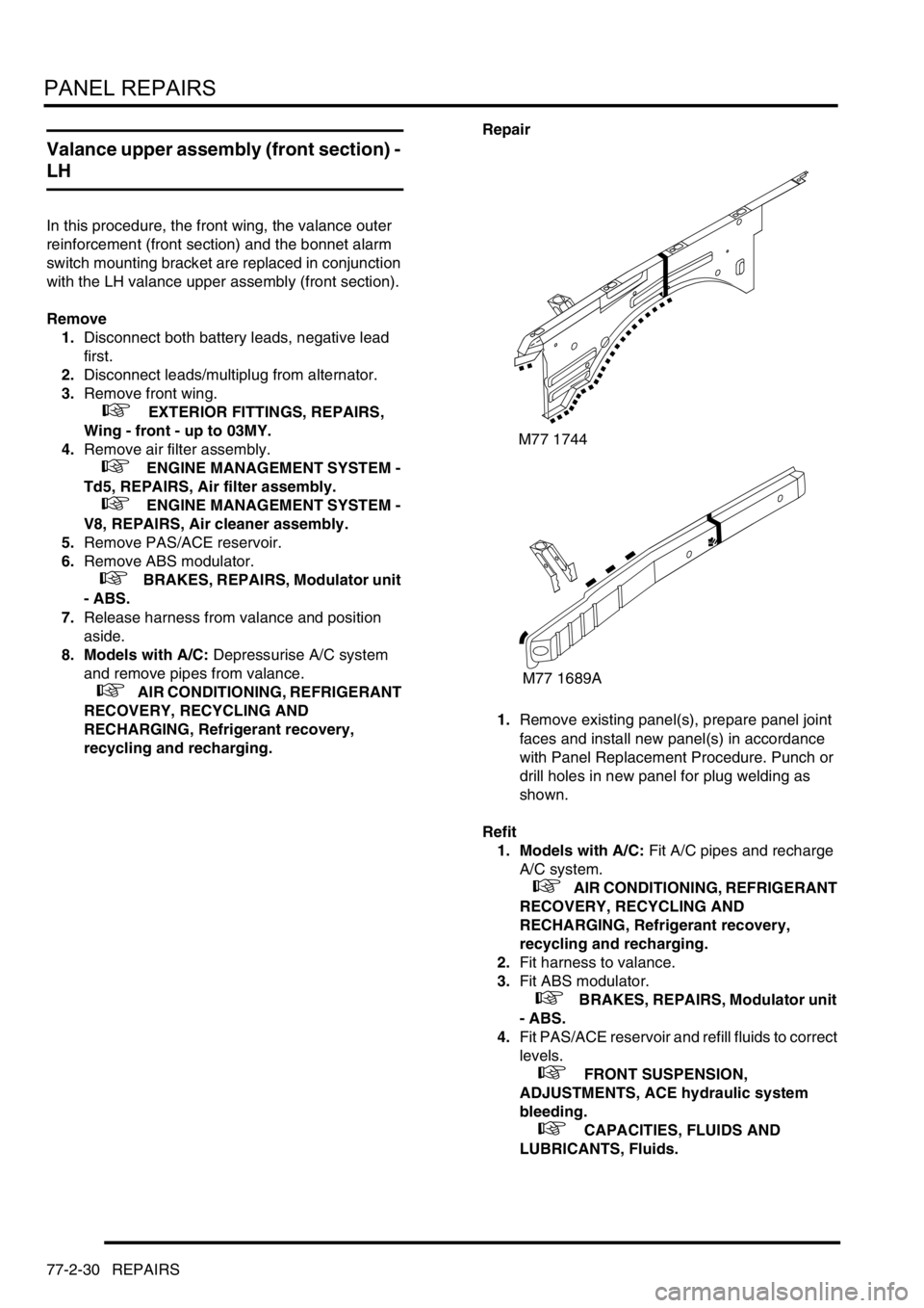
1.Remove existing panel(s), prepare panel joint
faces and install new panel(s) in accordance
with Panel Replacement Procedure. Punch or
drill holes in new panel for plug welding as
shown.
Refit
1. Models with A/C: Fit A/C pipes and recharge
A/C system.
+ AIR CONDITIONING, REFRIGERANT
RECOVERY, RECYCLING AND
RECHARGING, Refrigerant recovery,
recycling and recharging.
2.Fit harness to valance.
3.Fit ABS modulator.
+ BRAKES, REPAIRS, Modulator unit
- ABS.
4.Fit PAS/ACE reservoir and refill fluids to correct
levels.
+ FRONT SUSPENSION,
ADJUSTMENTS, ACE hydraulic system
bleeding.
+ CAPACITIES, FLUIDS AND
LUBRICANTS, Fluids.
M77 1744
M77 1689A