2002 JEEP LIBERTY Table of Contents
[x] Cancel search: Table of ContentsPage 1362 of 1803
EXHAUST SYSTEM
TABLE OF CONTENTS
page page
EXHAUST SYSTEM
DESCRIPTION..........................1
DIAGNOSIS AND TESTING - EXHAUST
SYSTEM.............................2
CATALYTIC CONVERTER
DESCRIPTION - CATALYTIC CONVERTER.....2
REMOVAL.............................2
INSPECTION...........................3
INSTALLATION..........................3CROSS-OVER PIPE
REMOVAL.............................3
INSTALLATION..........................3
HEAT SHIELDS
DESCRIPTION..........................4
MUFFLER
DESCRIPTION..........................4
REMOVAL.............................5
INSTALLATION..........................5
EXHAUST SYSTEM
DESCRIPTION
The basic exhaust system consists of an engine
exhaust manifold, exhaust down pipe, exhaust pipe,
exhaust heat shield(s), muffler and exhaust tailpipe
The exhaust system uses a single muffler.
The exhaust system must be properly aligned to
prevent stress, leakage and body contact. If the sys-
tem contacts any body panel, it will transfer objec-
tionable noises originating from the engine to the
body.
When inspecting an exhaust system, critically
inspect for cracked or loose joints, stripped screw or
bolt threads, corrosion damage and worn, cracked orbroken hangers. Replace all components that are
badly corroded or damaged. DO NOT attempt to
repair.
When replacement is required, use original equip-
ment parts (or equivalent). This will assure proper
alignment and provide acceptable exhaust noise lev-
els.
CAUTION: Avoid application of rust prevention com-
pounds or undercoating materials to exhaust sys-
tem floor pan exhaust heat shields. Light overspray
near the edges is permitted. Application of coating
will result in excessive floor pan temperatures and
objectionable fumes.
KJEXHAUST SYSTEM 11 - 1
Page 1368 of 1803
EXHAUST SYSTEM
TABLE OF CONTENTS
page page
EXHAUST SYSTEM
DESCRIPTION..........................1
DIAGNOSIS AND TESTING - EXHAUST
SYSTEM.............................2
CATALYTIC CONVERTER
DESCRIPTION - CATALYTIC CONVERTER.....2
REMOVAL.............................2
INSPECTION...........................3
INSTALLATION..........................3CROSS-OVER PIPE
REMOVAL.............................4
INSTALLATION..........................4
HEAT SHIELDS
DESCRIPTION..........................4
MUFFLER
DESCRIPTION..........................4
REMOVAL.............................4
INSTALLATION..........................5
EXHAUST SYSTEM
DESCRIPTION
The basic exhaust system consists of an engine
exhaust manifold, exhaust down pipe, exhaust pipe,
exhaust heat shield(s), muffler and exhaust tailpipe
The exhaust system uses a single muffler.
The exhaust system must be properly aligned to
prevent stress, leakage and body contact. If the sys-
tem contacts any body panel, it will transfer objec-
tionable noises originating from the engine to the
body.
When inspecting an exhaust system, critically
inspect for cracked or loose joints, stripped screw or
bolt threads, corrosion damage and worn, cracked orbroken hangers. Replace all components that are
badly corroded or damaged. DO NOT attempt to
repair.
When replacement is required, use original equip-
ment parts (or equivalent). This will assure proper
alignment and provide acceptable exhaust noise lev-
els.
CAUTION: Avoid application of rust prevention com-
pounds or undercoating materials to exhaust sys-
tem floor pan exhaust heat shields. Light overspray
near the edges is permitted. Application of coating
will result in excessive floor pan temperatures and
objectionable fumes.
KJEXHAUST SYSTEM 11s - 1
Page 1374 of 1803
FRAMES & BUMPERS
TABLE OF CONTENTS
page page
FRONT FASCIA
REMOVAL.............................1
INSTALLATION..........................2
REAR FASCIA
REMOVAL.............................2
INSTALLATION..........................2
REAR FASCIA SUPPORT
REMOVAL.............................3
INSTALLATION..........................3
FRAME
SPECIFICATIONS
SPECIFICATIONS - FRAME DIMENSIONS . . . 3
SPECIFICATIONS - TORQUE.............6
FRONT SKID PLATE
REMOVAL.............................6
INSTALLATION..........................6
ENGINE CRADLE CROSSMEMBER
REMOVAL.............................6
INSTALLATION..........................6TRANSFER CASE SKID PLATE
REMOVAL.............................7
INSTALLATION..........................7
REAR CROSSMEMBER
REMOVAL.............................7
INSTALLATION..........................7
FRONT TOW HOOK
REMOVAL.............................8
INSTALLATION..........................8
REAR TOW HOOK
REMOVAL.............................8
INSTALLATION..........................8
TRAILER HITCH
REMOVAL.............................9
INSTALLATION..........................9
FUEL TANK SKID PLATE
REMOVAL.............................9
INSTALLATION..........................9
FRONT FASCIA
REMOVAL
(1) Remove the grille. (Refer to 23 - BODY/EXTE-
RIOR/GRILLE - REMOVAL)
(2) Raise and support vehicle.
(3) Remove the front wheel opening flare moldings.
(Refer to 23 - BODY/EXTERIOR/FRONT WHEEL
OPENING FLARE MOLDINGS - REMOVAL)
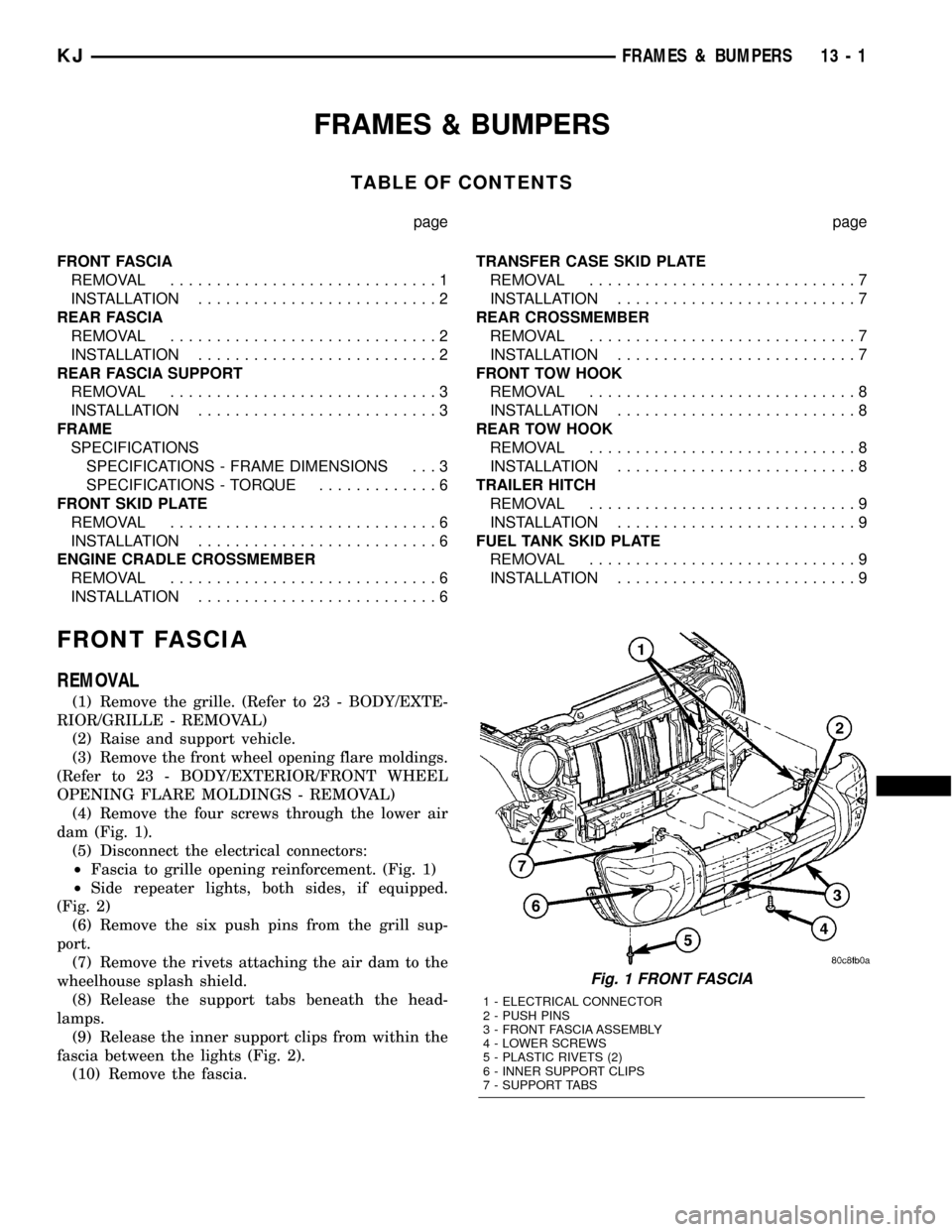
(4) Remove the four screws through the lower air
dam (Fig. 1).
(5) Disconnect the electrical connectors:
²Fascia to grille opening reinforcement. (Fig. 1)
²Side repeater lights, both sides, if equipped.
(Fig. 2)
(6) Remove the six push pins from the grill sup-
port.
(7) Remove the rivets attaching the air dam to the
wheelhouse splash shield.
(8) Release the support tabs beneath the head-
lamps.
(9) Release the inner support clips from within the
fascia between the lights (Fig. 2).
(10) Remove the fascia.
Fig. 1 FRONT FASCIA
1 - ELECTRICAL CONNECTOR
2 - PUSH PINS
3 - FRONT FASCIA ASSEMBLY
4 - LOWER SCREWS
5 - PLASTIC RIVETS (2)
6 - INNER SUPPORT CLIPS
7 - SUPPORT TABS
KJFRAMES & BUMPERS 13 - 1
Page 1383 of 1803
FUEL SYSTEM
TABLE OF CONTENTS
page page
FUEL DELIVERY..........................1FUEL INJECTION........................29
FUEL DELIVERY
TABLE OF CONTENTS
page page
FUEL DELIVERY
DESCRIPTION..........................2
OPERATION............................3
DIAGNOSIS AND TESTING - FUEL
PRESSURE LEAK DOWN TEST...........3
STANDARD PROCEDURE - FUEL SYSTEM
PRESSURE RELEASE...................4
SPECIFICATIONS
FUEL SYSTEM PRESSURE..............5
TORQUE.............................5
SPECIAL TOOLS
FUEL SYSTEM........................6
FLOW MANAGEMENT VALVE
DESCRIPTION..........................6
OPERATION............................6
REMOVAL.............................6
INSTALLATION..........................7
FUEL FILTER
DESCRIPTION..........................7
REMOVAL.............................7
INSTALLATION..........................8
FUEL LEVEL SENDING UNIT / SENSOR
DESCRIPTION..........................9
OPERATION............................9
DIAGNOSIS AND TESTING - FUEL LEVEL
SENDING UNIT........................9
REMOVAL.............................9
INSTALLATION.........................10
FUEL LINES
DESCRIPTION.........................10
QUICK CONNECT FITTING
DESCRIPTION.........................10
STANDARD PROCEDURE - QUICK-CONNECT
FITTINGS...........................10
FUEL PRESSURE REGULATOR
DESCRIPTION.........................13OPERATION...........................14
REMOVAL.............................14
INSTALLATION.........................14
FUEL PUMP
DESCRIPTION.........................15
OPERATION...........................15
DIAGNOSIS AND TESTING
DIAGNOSIS AND TESTING - FUEL PUMP
CAPACITY TEST......................15
DIAGNOSIS AND TESTING - FUEL PUMP
PRESSURE TEST.....................15
DIAGNOSIS AND TESTING - FUEL PUMP
AMPERAGE TEST.....................16
FUEL PUMP MODULE
DESCRIPTION.........................18
OPERATION...........................18
REMOVAL.............................18
INSTALLATION.........................19
FUEL RAIL
DESCRIPTION.........................21
OPERATION...........................21
REMOVAL.............................22
INSTALLATION.........................24
FUEL TANK
DESCRIPTION.........................24
OPERATION...........................24
REMOVAL.............................25
INSTALLATION.........................27
FUEL TANK CHECK VALVE
DESCRIPTION.........................28
OPERATION...........................28
REMOVAL.............................28
INSTALLATION.........................28
INLET FILTER
REMOVAL.............................28
INSTALLATION.........................28
KJFUEL SYSTEM 14 - 1
Page 1411 of 1803
FUEL INJECTION
TABLE OF CONTENTS
page page
FUEL INJECTION
DESCRIPTION.........................29
ACCELERATOR PEDAL
REMOVAL.............................29
INSTALLATION.........................30
CRANKSHAFT POSITION SENSOR
DESCRIPTION.........................30
OPERATION...........................31
REMOVAL.............................31
INSTALLATION.........................32
FUEL INJECTOR
DESCRIPTION.........................33
OPERATION
OPERATION - FUEL INJECTOR..........33
OPERATION - PCM OUTPUT............33
DIAGNOSIS AND TESTING - FUEL INJECTOR . 33
REMOVAL.............................34
INSTALLATION.........................34
FUEL PUMP RELAY
DESCRIPTION.........................34
OPERATION...........................34
DIAGNOSIS AND TESTING - FUEL PUMP
RELAY..............................34
REMOVAL.............................34
INSTALLATION.........................34
IDLE AIR CONTROL MOTOR
DESCRIPTION.........................35
OPERATION...........................35
REMOVAL.............................36INSTALLATION.........................36
INTAKE AIR TEMPERATURE SENSOR
DESCRIPTION.........................36
OPERATION...........................36
REMOVAL.............................37
INSTALLATION.........................38
MAP SENSOR
DESCRIPTION.........................38
OPERATION...........................38
REMOVAL.............................39
INSTALLATION.........................40
OXYGEN SENSOR
DESCRIPTION.........................40
OPERATION...........................40
REMOVAL.............................41
INSTALLATION.........................43
THROTTLE BODY
DESCRIPTION.........................43
OPERATION...........................43
REMOVAL.............................43
INSTALLATION.........................44
THROTTLE CONTROL CABLE
REMOVAL.............................45
INSTALLATION.........................46
THROTTLE POSITION SENSOR
DESCRIPTION.........................47
OPERATION...........................47
REMOVAL.............................47
INSTALLATION.........................48
FUEL INJECTION
DESCRIPTION
The Powertrain Control Module (PCM) operates
the fuel injection system. Refer to Powertrain Control
Module in Electronic Control Modules for informa-
tion.
ACCELERATOR PEDAL
REMOVAL
The accelerator pedal is serviced as a complete
assembly including the bracket.The accelerator pedal is connected to the upper
part of the accelerator pedal arm by a plastic
retainer (clip) (Fig. 1). This plastic retainer snaps
into the top of the accelerator pedal arm.
(1) From inside the vehicle, hold up accelerator
pedal. Remove plastic cable retainer (clip) and throt-
tle cable core wire from upper end of accelerator
pedal arm (Fig. 1). Plastic cable retainer (clip) snaps
into pedal arm.
(2) Remove 2 accelerator pedal mounting bracket
nuts. Remove accelerator pedal assembly.
KJFUEL INJECTION 14 - 29
Page 1431 of 1803
STEERING
TABLE OF CONTENTS
page page
STEERING
DESCRIPTION..........................1
OPERATION............................1
DIAGNOSIS AND TESTING
DIAGNOSIS AND TESTING - POWER
STEERING SYSTEM....................1DIAGNOSIS AND TESTING - POWER
STEERING FLOW AND PRESSURE........3
COLUMN...............................5
GEAR.................................13
LINKAGE..............................16
PUMP.................................17
STEERING
DESCRIPTION
Power steering systems consist of:
²Steering column & Intermediate Shaft
²Rack and pinion steering gear
²Belt driven hydraulic steering pump
²Pump pressure, supply and return hoses
²Oil Cooler
OPERATION
The steering column intermediate shaft attaches
the steering column to the gear pinion. The rotation
of the pinion moves the gear rack from side-to-side.
This lateral action of the rack pushes and pulls the
tie rods to change the direction of the front wheels.
Power assist is provided by an engine mounted
hydraulic pump. The pump supplies hydraulic fluid
to the steering gear. All vehicles are equipped with
an oil cooler.
DIAGNOSIS AND TESTING
DIAGNOSIS AND TESTING - POWER STEERING SYSTEM
STEERING NOISE
There is some noise in all power steering systems. One of the most common is a hissing sound evident at a
standstill/parking, or when the steering is at the end of it's travel. Hiss is a high frequency noise similar to that
of a water tap being closed slowly. The noise is present in all valves that have a high velocity fluid passing through
an orifice. There is no relationship between this noise and steering performance.
CONDITION POSSIBLE CAUSES CORRECTION
OBJECTIONAL HISS OR
WHISTLE1. Steering intermediate shaft to dash panel
seal.1. Check and repair seal at dash
panel.
2. Noisy valve in power steering gear. 2. Replace steering gear.
1. Gear mounting bolts loose. 1. Tighten bolts to specification.
2. Loose or damaged suspension
components.2. Inspect and repair suspension.
3. Internal gear noise. 3. Replace steering gear.
4. Loose or damaged intermediate shaft or
column.4. Inspect and repair or replace.
MOAN Pressure hose in contact with other
components.Reposition hose.
CHIRP OR SQUEAL 1. Loose belt. 1. Adjust or replace.
KJSTEERING 19 - 1
Page 1435 of 1803
COLUMN
TABLE OF CONTENTS
page page
COLUMN
DESCRIPTION..........................5
OPERATION - SERVICE PRECAUTIONS......5
REMOVAL.............................5
INSTALLATION..........................7
SPECIFICATIONS
TORQUE CHART......................8
SPECIAL TOOLS
STEERING COLUMN....................8
IGNITION SWITCH
DESCRIPTION..........................8
DIAGNOSIS AND TESTING - IGNITION
SWITCH.............................8
REMOVAL
IGNITION SWITCH REMOVAL.............9INSTALLATION
IGNITION SWITCH INSTALLATION.........9
KEY-IN IGNITION SWITCH
DESCRIPTION.........................10
DIAGNOSIS AND TESTING - KEY-IN IGNITION
SWITCH............................10
LOCK CYLINDER
REMOVAL.............................10
INSTALLATION.........................11
INTERMEDIATE SHAFT
REMOVAL.............................11
INSTALLATION.........................11
STEERING WHEEL
REMOVAL.............................12
INSTALLATION.........................12
COLUMN
DESCRIPTION
The standard non-tilt and tilt steering column has
been designed to be serviced as an assembly. The col-
umn is connected to the steering gear with a one
piece shaft. The upper half has a support bearing
mounted to a bracket. The bracket mounts to the
frame rail with two nuts. The shaft is serviceable.
The key cylinder, switches, clock spring, trim shrouds
and steering wheel are serviced separately.
OPERATION - SERVICE PRECAUTIONS
Safety goggles should be worn at all times when
working on steering columns.
To service the steering wheel, switches or airbag,
refer to Electrical - Restraints and follow all WARN-
INGS and CAUTIONS.
WARNING: THE AIRBAG SYSTEM IS A SENSITIVE,
COMPLEX ELECTRO-MECHANICAL UNIT. BEFORE
ATTEMPTING TO DIAGNOSE, REMOVE OR INSTALL
THE AIRBAG SYSTEM COMPONENTS YOU MUST
FIRST DISCONNECT AND ISOLATE THE BATTERY
NEGATIVE (GROUND) CABLE. THEN WAIT TWOMINUTES FOR THE SYSTEM CAPACITOR TO DIS-
CHARGE. FAILURE TO DO SO COULD RESULT IN
ACCIDENTAL DEPLOYMENT OF THE AIRBAG AND
POSSIBLE PERSONAL INJURY. THE FASTENERS,
SCREWS, AND BOLTS, ORIGINALLY USED FOR
THE AIRBAG COMPONENTS, HAVE SPECIAL COAT-
INGS AND ARE SPECIFICALLY DESIGNED FOR THE
AIRBAG SYSTEM. THEY MUST NEVER BE
REPLACED WITH ANY SUBSTITUTES. ANYTIME A
NEW FASTENER IS NEEDED, REPLACE WITH THE
CORRECT FASTENERS PROVIDED IN THE SERVICE
PACKAGE OR FASTENERS LISTED IN THE PARTS
BOOKS.REMOVAL
(1) Position front wheelsstraight ahead.
(2) Remove and isolate the negative ground cable
from the battery.
(3) Remove the airbag, (Refer to 8 - ELECTRICAL/
RESTRAINTS/DRIVER AIRBAG - REMOVAL).
NOTE: If equipped with cruise control, disconnect
clock spring harness from the cruise switch har-
ness on the steering wheel.
KJCOLUMN 19 - 5
Page 1443 of 1803
GEAR
TABLE OF CONTENTS
page page
GEAR
DESCRIPTION.........................13
OPERATION...........................13
REMOVAL
REMOVAL - 4WD......................13
REMOVAL - 2WD......................14
INSTALLATION
INSTALLATION - 4WD..................14INSTALLATION - 2WD..................14
SPECIFICATIONS
TORQUE CHART......................15
SPECIAL TOOLS
OUTER TIE ROD END REMOVAL TOOL....15
GEAR
DESCRIPTION
A rack and pinion steering gear (Fig. 1) is made up
of two main components, the pinon shaft and the
rack. The gear cannot be adjusted or internally ser-
viced. If a malfunction or a fluid leak occurs, the gear
must be replaced as an assembly.
OPERATION
The steering column intermediate shaft is attached
to the gear pinion. The rotation of the pinion moves
the gear rack from side-to-side. This lateral action of
the rack pushes and pulls the tie rods, which are
connected to the steering knuckles to change the
direction of the front wheels.
REMOVAL
REMOVAL - 4WD
(1) Siphon the power steering fluid from the power
steering reservoir.
(2) Lock the steering wheel to prevent spinning of
the clockspring.
(3) Raise and support the vehicle.
(4) Remove the skid plate from under the front
end to gain access to the gear (Refer to 13 - FRAME
& BUMPERS/FRAME/FRONT SKID PLATE -
REMOVAL).
(5) Remove the front tire and wheel assemblies.
NOTE: Mark the alignment adjusting cams for eas-
ier installation.
(6) Remove the lower control arms. (Refer to 2 -
SUSPENSION/FRONT/LOWER CONTROL ARM -
REMOVAL).
(7) Remove the front axle. (Refer to 3 - DIFFER-
ENTIAL & DRIVELINE/FRONT AXLE - REMOV-
AL).
(8) Remove the tie rod end nuts.
(9) Separate tie rod ends from the knuckles with
Puller C-3894-A.
(10) Remove the intermediate shaft lower coupler
bolt and slide the coupler off the gear (Fig. 2).
(11) Remove power steering pressure hose bracket
(Fig. 3).
(12) Remove the power steering lines from the
gear (Fig. 2).
(13) Remove the mounting bolts from the gear to
the front cradle (Fig. 3).
(14) Remove the steering gear from the vehicle.
Fig. 1 Rack & Pinion Steering Gear
1 - TIE ROD - INNER
2 - TIE ROD - INNER
3 - TIE ROD END - OUTER LH
4 - BOOTS
5 - TIE ROD END - OUTER RH
KJGEAR 19 - 13