2002 JEEP LIBERTY Table of Contents
[x] Cancel search: Table of ContentsPage 1446 of 1803
LINKAGE
TABLE OF CONTENTS
page page
LINKAGE
STANDARD PROCEDURE - STEERING
LINKAGE............................16TIE ROD END
REMOVAL.............................16
INSTALLATION.........................16
LINKAGE
STANDARD PROCEDURE - STEERING LINKAGE
The tie rod end and ball stud seals should be
inspected during all oil changes. If a seal is damaged,
replace the tie rod.
CAUTION: If any steering components are replaced
or serviced an alignment must be performed, to
ensure the vehicle meets all alignment specifica-
tions.
TIE ROD END
REMOVAL
(1) Raise and support the vehicle.
(2) Remove the tire and wheel assembly.
NOTE: Mark the tie rod end jam nuts on the steer-
ing gear for easier installation.
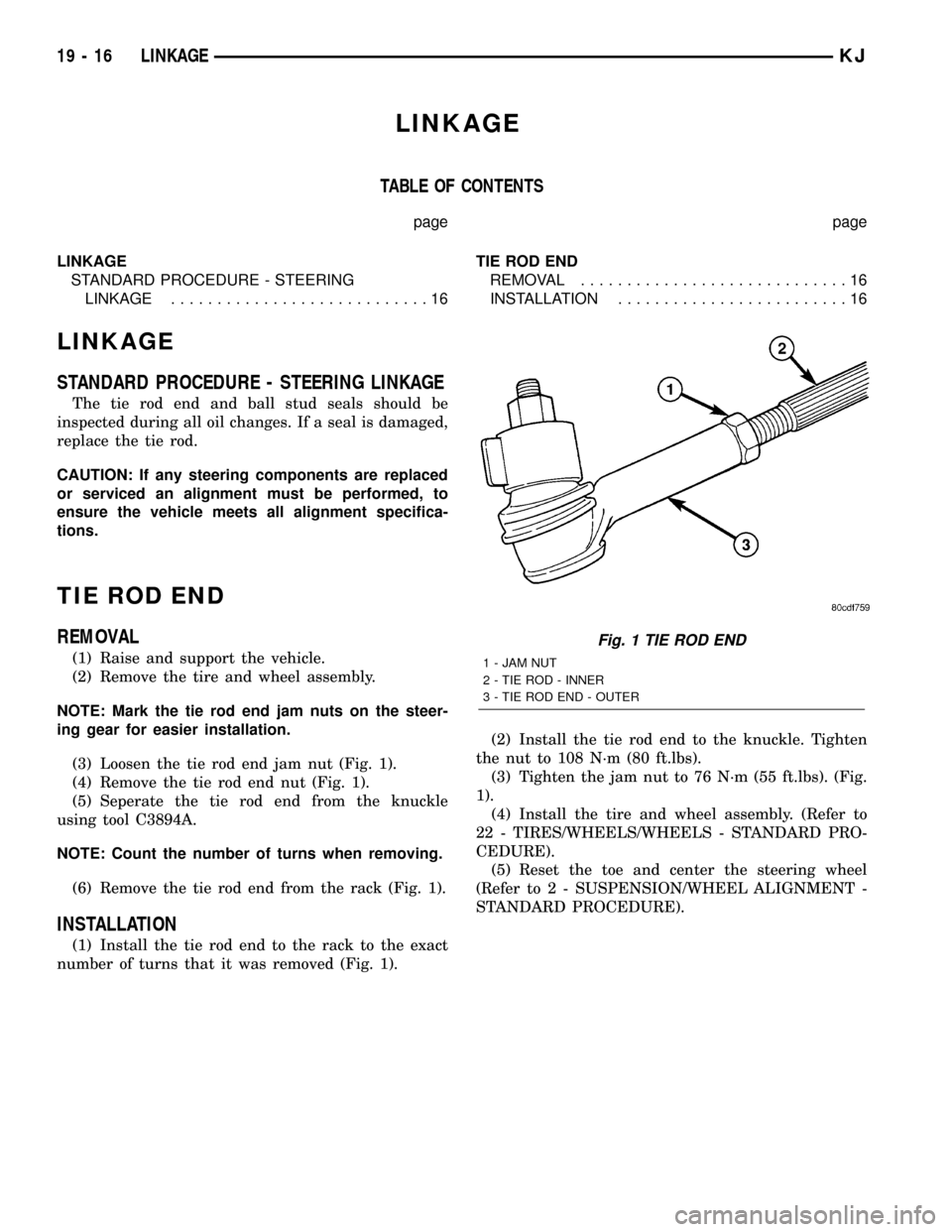
(3) Loosen the tie rod end jam nut (Fig. 1).
(4) Remove the tie rod end nut (Fig. 1).
(5) Seperate the tie rod end from the knuckle
using tool C3894A.
NOTE: Count the number of turns when removing.
(6) Remove the tie rod end from the rack (Fig. 1).
INSTALLATION
(1) Install the tie rod end to the rack to the exact
number of turns that it was removed (Fig. 1).(2) Install the tie rod end to the knuckle. Tighten
the nut to 108 N´m (80 ft.lbs).
(3) Tighten the jam nut to 76 N´m (55 ft.lbs). (Fig.
1).
(4) Install the tire and wheel assembly. (Refer to
22 - TIRES/WHEELS/WHEELS - STANDARD PRO-
CEDURE).
(5) Reset the toe and center the steering wheel
(Refer to 2 - SUSPENSION/WHEEL ALIGNMENT -
STANDARD PROCEDURE).
Fig. 1 TIE ROD END
1 - JAM NUT
2 - TIE ROD - INNER
3 - TIE ROD END - OUTER
19 - 16 LINKAGEKJ
Page 1447 of 1803
PUMP
TABLE OF CONTENTS
page page
PUMP
DESCRIPTION.........................17
OPERATION...........................17
STANDARD PROCEDURE - POWER
STEERING PUMP - INITIAL OPERATION....18
REMOVAL
REMOVAL - 3.7L......................18
REMOVAL - 2.4L......................18
INSTALLATION
INSTALLATION - 3.7L..................19
INSTALLATION - 2.4L..................19
SPECIFICATIONS
TORQUE CHART......................19
SPECIAL TOOLS
POWER STEERING PUMP..............20
FLUID COOLER
DESCRIPTION.........................20
OPERATION...........................20
REMOVAL.............................20
INSTALLATION.........................20
HOSES
REMOVAL
REMOVAL - PRESSURE HOSE...........21
REMOVAL - RETURN HOSE (GEAR TO THE
COOLER)...........................21REMOVAL - RETURN HOSE (RESERVOIR
TO THE COOLER).....................21
INSTALLATION
INSTALLATION - PRESSURE HOSE.......21
INSTALLATION - RETURN HOSE (GEAR TO
THE COOLER)........................22
INSTALLATION - RETURN HOSE
(RESERVOIR TO THE COOLER)..........22
POWER STEERING PRESSURE SWITCH
DESCRIPTION.........................22
OPERATION...........................22
REMOVAL.............................22
INSTALLATION.........................22
PULLEY
REMOVAL.............................23
INSTALLATION.........................23
RESERVOIR
REMOVAL
REMOVAL - 3.7L......................24
REMOVAL - 2.4L......................24
INSTALLATION
INSTALLATION - 3.7L..................24
INSTALLATION - 2.4L..................24
PUMP
DESCRIPTION
Hydraulic pressure for the power steering system
is provided by a belt driven power steering pump
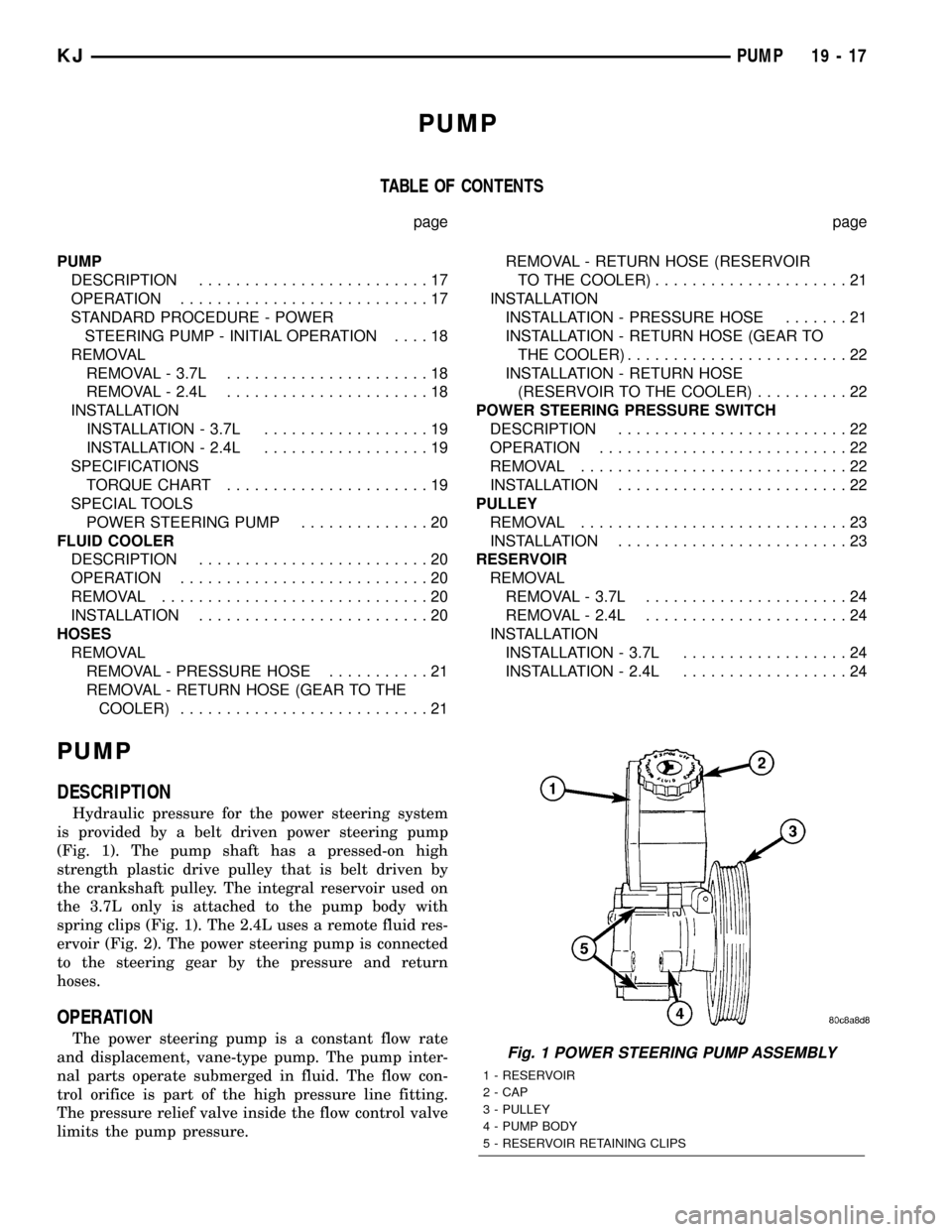
(Fig. 1). The pump shaft has a pressed-on high
strength plastic drive pulley that is belt driven by
the crankshaft pulley. The integral reservoir used on
the 3.7L only is attached to the pump body with
spring clips (Fig. 1). The 2.4L uses a remote fluid res-
ervoir (Fig. 2). The power steering pump is connected
to the steering gear by the pressure and return
hoses.
OPERATION
The power steering pump is a constant flow rate
and displacement, vane-type pump. The pump inter-
nal parts operate submerged in fluid. The flow con-
trol orifice is part of the high pressure line fitting.
The pressure relief valve inside the flow control valve
limits the pump pressure.Fig. 1 POWER STEERING PUMP ASSEMBLY
1 - RESERVOIR
2 - CAP
3 - PULLEY
4 - PUMP BODY
5 - RESERVOIR RETAINING CLIPS
KJPUMP 19 - 17
Page 1455 of 1803
TIRES/WHEELS
TABLE OF CONTENTS
page page
TIRES/WHEELS
DIAGNOSIS AND TESTING - TIRES AND
WHEEL RUNOUT......................1
STANDARD PROCEDURE
STANDARD PROCEDURE - TIRE ROTATION . 2
STANDARD PROCEDURE - MATCH
MOUNTING...........................3
STANDARD PROCEDURE - WHEEL
BALANCING..........................4
TIRES
DESCRIPTION
DESCRIPTION - TIRES..................6
DESCRIPTION - RADIAL-PLY TIRES........6
DESCRIPTION - SPARE TIRE
&TEMPORARY........................6
DESCRIPTION - REPLACEMENT TIRES.....7
DIAGNOSIS AND TESTING
DIAGNOSIS AND TESTING - TIRE
INFLATION...........................7
DIAGNOSIS AND TESTING - TREAD WEAR
INDICATORS..........................8
DIAGNOSIS AND TESTING - TIRE WEAR
PATTERNS...........................8DIAGNOSIS AND TESTING - TIRE NOISE
OR VIBRATION........................8
STANDARD PROCEDURE - REPAIRING
LEAKS...............................8
CLEANING.............................8
SPECIFICATIONS........................8
SPARE TIRE
REMOVAL.............................8
INSTALLATION..........................9
WHEELS
DESCRIPTION..........................9
DIAGNOSIS AND TESTING - WHEELS.......10
STANDARD PROCEDURE
STANDARD PROCEDURE - WHEEL
REPLACEMENT.......................10
STANDARD PROCEDURE - WHEEL
MOUNTING..........................10
SPECIFICATIONS
SPECIFICATION......................11
STUDS
REMOVAL.............................11
INSTALLATION.........................11
TIRES/WHEELS
DIAGNOSIS AND TESTING - TIRES AND
WHEEL RUNOUT
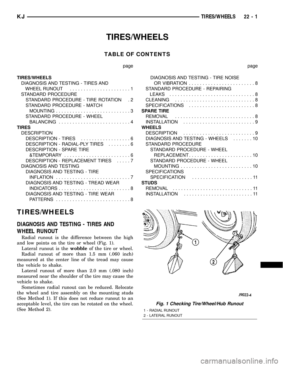
Radial runout is the difference between the high
and low points on the tire or wheel (Fig. 1).
Lateral runout is thewobbleof the tire or wheel.
Radial runout of more than 1.5 mm (.060 inch)
measured at the center line of the tread may cause
the vehicle to shake.
Lateral runout of more than 2.0 mm (.080 inch)
measured near the shoulder of the tire may cause the
vehicle to shake.
Sometimes radial runout can be reduced. Relocate
the wheel and tire assembly on the mounting studs
(See Method 1). If this does not reduce runout to an
acceptable level, the tire can be rotated on the wheel.
(See Method 2).
Fig. 1 Checking Tire/Wheel/Hub Runout
1 - RADIAL RUNOUT
2 - LATERAL RUNOUT
KJTIRES/WHEELS 22 - 1
Page 1466 of 1803
BODY
TABLE OF CONTENTS
page page
BODY
WARNING
SAFETY PRECAUTIONS AND WARNINGS . . . 1
DIAGNOSIS AND TESTING
DIAGNOSIS AND TESTING - WATER LEAKS . 2
DIAGNOSIS AND TESTING - WIND NOISE . . . 3
STANDARD PROCEDURE
STANDARD PROCEDURE - BODY
LUBRICATION.........................3
STANDARD PROCEDURE - HEAT STAKING . . 3
SPECIFICATIONS........................4
SPECIAL TOOLS
BODY...............................5BODY STRUCTURE.......................6
HOOD................................119
DOOR - FRONT........................121
DOORS - REAR........................128
SWING GATE..........................135
EXTERIOR............................140
INSTRUMENT PANEL....................147
INTERIOR.............................156
PAINT................................162
SEATS...............................164
STATIONARY GLASS....................172
SUNROOF.............................175
WEATHERSTRIP/SEALS..................185
BODY
WARNING
SAFETY PRECAUTIONS AND WARNINGS
WARNING: EYE PROTECTION SHOULD BE USED
WHEN SERVICING GLASS COMPONENTS. PER-
SONAL INJURY CAN RESULT.
²USE A OSHA APPROVED BREATHING FILTER
WHEN SPRAYING PAINT OR SOLVENTS IN A CON-
FINED AREA. PERSONAL INJURY CAN RESULT.
²AVOID PROLONGED SKIN CONTACT WITH
PETROLEUM OR ALCOHOL±BASED CLEANING
SOLVENTS. PERSONAL INJURY CAN RESULT.
²DO NOT STAND UNDER A HOISTED VEHICLE
THAT IS NOT PROPERLY SUPPORTED ON SAFETY
STANDS. PERSONAL INJURY CAN RESULT.
CAUTION: When holes must be drilled or punched
in an inner body panel, verify depth of space to the
outer body panel, electrical wiring, or other compo-
nents. Damage to vehicle can result.
²Do not weld exterior panels unless combustible
material on the interior of vehicle is removed from
the repair area. Fire or hazardous conditions, can
result.
²Always have a fire extinguisher ready for use
when welding.
²Disconnect the negative (-) cable clamp from
the battery when servicing electrical components
that are live when the ignition is OFF. Damage to
electrical system can result.²Do not use abrasive chemicals or compounds
on painted surfaces. Damage to finish can result.
²Do not use harsh alkaline based cleaning sol-
vents on painted or upholstered surfaces. Damage
to finish or color can result.
²Do not hammer or pound on plastic trim panel
when servicing interior trim. Plastic panels can
break.
DaimlerChrysler Corporation uses many different
types of push-in fasteners to secure the interior and
exterior trim to the body. Most of these fasteners can
be reused to assemble the trim during various repair
procedures. At times, a push-in fastener cannot be
removed without damaging the fastener or the com-
ponent it is holding. If it is not possible to remove a
fastener without damaging a component or body, cut
or break the fastener and use a new one when
installing the component. Never pry or pound on a
plastic or pressed-board trim component. Using a
suitable fork-type prying device, pry the fastener
from the retaining hole behind the component being
removed. When installing, verify fastener alignment
with the retaining hole by hand. Push directly on or
over the fastener until it seats. Apply a low-force pull
to the panel to verify that it is secure.
When it is necessary to remove components to ser-
vice another, it should not be necessary to apply
excessive force or bend a component to remove it.
Before damaging a trim component, verify hidden
fasteners or captured edges holding the component in
place.
KJBODY 23 - 1
Page 1471 of 1803
BODY STRUCTURE
TABLE OF CONTENTS
page page
ASSEMBLY
SPECIFICATIONS
SPECIFICATION.......................6
WELD AND STRUCTURAL ADHESIVE
LOCATIONS
SPECIFICATIONS........................9SEALER LOCATIONS
SPECIFICATIONS.......................87
OPENING DIMENSIONS
SPECIFICATIONS......................111
GAP AND FLUSH
SPECIFICATIONS......................116
ASSEMBLY
SPECIFICATIONS
SPECIFICATION
INDEX
DESCRIPTION FIGURE
COMPLETE BODY STRUCTURE VIEWS ( 1 )
BODY STRUCTURE - SECTIONS ( 2 )
23 - 6 BODY STRUCTUREKJ
Page 1584 of 1803
HOOD
TABLE OF CONTENTS
page page
HINGE
REMOVAL............................119
INSTALLATION........................119
HOOD
REMOVAL............................119
INSTALLATION........................119
ADJUSTMENTS
ADJUSTMENT.......................119
LATCH
REMOVAL............................120INSTALLATION........................120
LATCH RELEASE CABLE
REMOVAL............................120
INSTALLATION........................120
SUPPORT CYLINDER
REMOVAL............................120
INSTALLATION........................120
LATCH RELEASE HANDLE
REMOVAL............................120
INSTALLATION........................120
HINGE
REMOVAL
NOTE: It is not necessary to remove the hood to
replace one or both hinges. The hinges can be
replaced one at a time.
(1) Raise and support hood.
(2) Using a grease pencil or equivalent, mark posi-
tion of hinge.
(3) Remove hood support cylinder. (Refer to 23 -
BODY/HOOD/SUPPORT CYLINDER - REMOVAL)
(4) Remove nuts attaching hinge to hood.
(5) Remove bolts attaching hinge to body.
(6) Separate hinge from vehicle.
INSTALLATION
(1) Position hinge on vehicle and align reference
marks.
(2) Install bolts attaching hinge to body and
tighten to 28 N´m (21 ft. lbs.).
(3) Install nuts attaching hinge to hood 12 N´m (9
ft. lbs.).
(4) Install hood hinge support cylinder. (Refer to
23 - BODY/HOOD/SUPPORT CYLINDER - INSTAL-
LATION)
HOOD
REMOVAL
(1) Raise hood.
(2) Using a grease pencil or equivalent, mark loca-
tion of hood hinges on hood for installation align-
ment.
(3) Remove bolts attaching hinges to hood.
(4) With the aid of a helper, remove hood from
vehicle.
INSTALLATION
(1) Position hood on hinges.
(2) Install bolts finger-tight.
(3) Align hinges with installation reference marks
and tighten bolts to 12 N´m (9 ft. lbs.).
(4) Inspect hood for proper alignment and adjust
as necessary.
ADJUSTMENTS
ADJUSTMENT
(1) If hood is low in relation to cowl panel, insert
shims between hinge and hood.
(2) Adjust hood bumper in or out to adjust hood-
to-fender height alignment.
(3) Adjust the hood latch as necessary. Tighten the
nuts to 11 N´m (8 ft. lbs.).
(4) Align the latch striker so that striker enters
the latch squarely and without binding.
KJHOOD 23 - 119
Page 1586 of 1803
DOOR - FRONT
TABLE OF CONTENTS
page page
CHECK STRAP
REMOVAL............................121
INSTALLATION........................121
DOOR
REMOVAL............................122
INSTALLATION........................122
DOOR GLASS
REMOVAL............................122
INSTALLATION........................122
EXTERIOR HANDLE
REMOVAL............................123
INSTALLATION........................123
GLASS RUN CHANNEL
REMOVAL............................123
INSTALLATION........................123
HINGE
REMOVAL............................123
INSTALLATION........................123
LATCH
REMOVAL............................124
INSTALLATION........................124ADJUSTMENTS
ADJUSTMENT.......................124
LATCH STRIKER
REMOVAL............................124
INSTALLATION........................124
LOCK CYLINDER
REMOVAL............................125
INSTALLATION........................125
TRIM PANEL
REMOVAL............................125
INSTALLATION........................126
WATERDAM
REMOVAL............................126
INSTALLATION........................126
WINDOW REGULATOR - MANUAL
REMOVAL............................126
INSTALLATION........................126
WINDOW REGULATOR - ELECTRIC
REMOVAL............................126
INSTALLATION........................126
CHECK STRAP
REMOVAL
(1) Remove the waterdam. (Refer to 23 - BODY/
DOOR - FRONT/WATERDAM - REMOVAL)
(2) Remove screws attaching door check to A-pillar.
(3) Remove the two nuts and remove the door
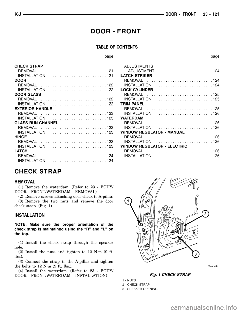
check strap. (Fig. 1)
INSTALLATION
NOTE: Make sure the proper orientation of the
check strap is maintained using the ªRº and ªLº on
the top.
(1) Install the check strap through the speaker
hole.
(2) Install the nuts and tighten to 12 N´m (9 ft.
lbs.).
(3) Connect the strap to the A-pillar and tighten
the bolts to 12 N´m (9 ft. lbs.).
(4) Install the waterdam. (Refer to 23 - BODY/
DOOR - FRONT/WATERDAM - INSTALLATION)
Fig. 1 CHECK STRAP
1 - NUTS
2 - CHECK STRAP
3 - SPEAKER OPENING
KJDOOR - FRONT 23 - 121
Page 1593 of 1803
DOORS - REAR
TABLE OF CONTENTS
page page
CHECK STRAP
REMOVAL............................128
INSTALLATION........................128
DOOR
REMOVAL............................129
INSTALLATION........................129
DOOR GLASS
REMOVAL............................129
INSTALLATION........................129
EXTERIOR HANDLE
REMOVAL............................130
INSTALLATION........................130
GLASS RUN CHANNEL
REMOVAL............................130
INSTALLATION........................130
HINGE
REMOVAL............................131
INSTALLATION........................131
LATCH
REMOVAL............................131INSTALLATION........................131
ADJUSTMENTS
ADJUSTMENT.......................131
LATCH STRIKER
REMOVAL............................132
INSTALLATION........................132
TRIM PANEL
REMOVAL............................132
INSTALLATION........................132
WATERDAM
REMOVAL............................133
INSTALLATION........................133
WINDOW REGULATOR - MANUAL
REMOVAL............................133
INSTALLATION........................133
WINDOW REGULATOR - ELECTRIC
REMOVAL............................134
INSTALLATION........................134
CHECK STRAP
REMOVAL
(1) Remove the waterdam. (Refer to 23 - BODY/
DOORS - REAR/WATERDAM - REMOVAL)
(2) Remove screws attaching door check to b-pillar.
(3) Remove the two nuts and remove the door
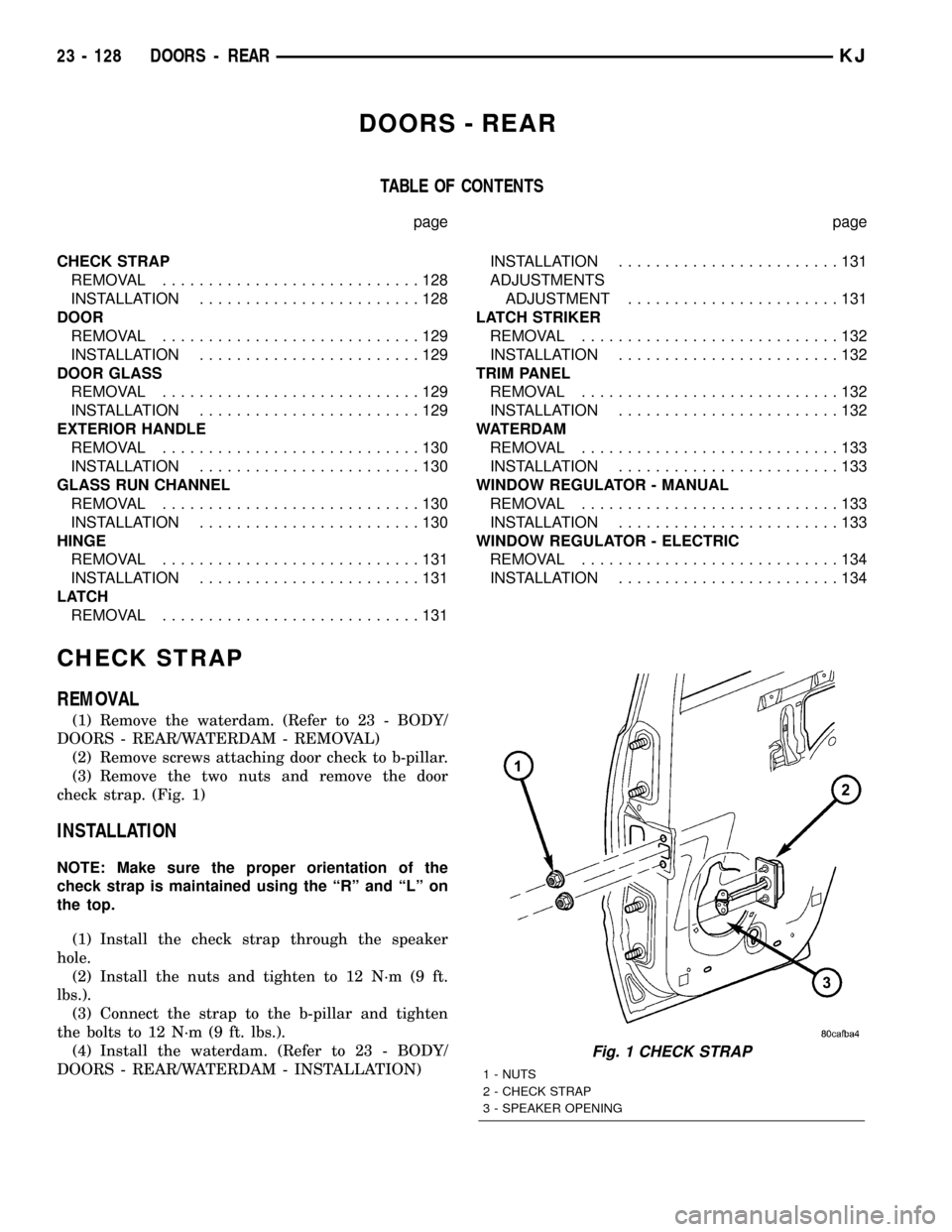
check strap. (Fig. 1)
INSTALLATION
NOTE: Make sure the proper orientation of the
check strap is maintained using the ªRº and ªLº on
the top.
(1) Install the check strap through the speaker
hole.
(2) Install the nuts and tighten to 12 N´m (9 ft.
lbs.).
(3) Connect the strap to the b-pillar and tighten
the bolts to 12 N´m (9 ft. lbs.).
(4) Install the waterdam. (Refer to 23 - BODY/
DOORS - REAR/WATERDAM - INSTALLATION)
Fig. 1 CHECK STRAP
1 - NUTS
2 - CHECK STRAP
3 - SPEAKER OPENING
23 - 128 DOORS - REARKJ