2002 JEEP LIBERTY oil level
[x] Cancel search: oil levelPage 1299 of 1803
CRANKSHAFT
DESCRIPTION.........................32
OPERATION...........................33
STANDARD PROCEDURE - CRANKSHAFT
ENDPLAY ...........................33
REMOVAL.............................33
INSPECTION..........................34
INSTALLATION.........................34
CRANKSHAFT MAIN BEARINGS
STANDARD PROCEDURE - MAIN BEARING -
FITTING.............................35
CRANKSHAFT OIL SEAL - FRONT
REMOVAL.............................37
INSTALLATION.........................37
CRANKSHAFT OIL SEAL - REAR
REMOVAL.............................38
INSTALLATION.........................39
PISTON & CONNECTING ROD
DESCRIPTION.........................40
OPERATION...........................40
REMOVAL.............................40
INSTALLATION.........................41
PISTON RINGS
STANDARD PROCEDURE
PISTON RING - FITTING................42
VIBRATION DAMPER
REMOVAL.............................43
INSTALLATION.........................43
STRUCTURAL COLLAR
REMOVAL.............................44
INSTALLATION.........................44
ENGINE MOUNTING
DESCRIPTION.........................44
FRONT MOUNT
REMOVAL.............................44
INSTALLATION.........................44
REAR MOUNT
REMOVAL.............................45
INSTALLATION.........................45
LUBRICATION
DESCRIPTION.........................46
OPERATION...........................46
DIAGNOSIS AND TESTING - ENGINE OIL
PRESSURE CHECKING.................46
OIL
STANDARD PROCEDURE
ENGINE OIL LEVEL CHECK.............47
STANDARD PROCEDURE - ENGINE OIL
AND FILTER CHANGE..................47
OIL FILTER
DESCRIPTION.........................47
REMOVAL.............................47
INSTALLATION.........................47
OIL PAN
REMOVAL.............................48INSTALLATION.........................48
OIL PRESSURE SENSOR/SWITCH
DESCRIPTION.........................48
OPERATION...........................48
OIL PUMP
REMOVAL.............................49
DISASSEMBLY.........................49
CLEANING............................49
INSPECTION..........................50
ASSEMBLY............................50
INSTALLATION.........................50
INTAKE MANIFOLD
DESCRIPTION.........................51
OPERATION...........................51
DIAGNOSIS AND TESTING - INTAKE
MANIFOLD LEAKS.....................51
REMOVAL.............................52
INSPECTION..........................52
INSTALLATION.........................52
EXHAUST MANIFOLD
DESCRIPTION.........................53
OPERATION...........................53
REMOVAL.............................53
CLEANING............................53
INSPECTION..........................53
INSTALLATION.........................53
TIMING BELT COVER(S)
REMOVAL.............................53
INSTALLATION.........................53
TIMING BELT AND SPROCKET(S)
REMOVAL
REMOVAL - TIMING BELT...............55
REMOVAL - CRANKSHAFT SPROCKET....55
CLEANING............................55
INSTALLATION
INSTALLATION - CRANKSHAFT SPROCKET . 56
INSTALLATION - TIMING BELT...........56
TIMING BELT TENSIONER & PULLEY
REMOVAL.............................59
INSTALLATION.........................59
BALANCE SHAFT
DESCRIPTION.........................59
OPERATION...........................59
REMOVAL.............................60
INSTALLATION
BALANCE SHAFT TIMING...............61
BALANCE SHAFT CARRIER
REMOVAL.............................64
INSTALLATION.........................64
BALANCE SHAFT CHAIN
REMOVAL.............................64
INSTALLATION.........................64
9s - 2 ENGINEKJ
Page 1300 of 1803
ENGINE - 2.4L
DESCRIPTION
The 2.4 Liter (148 cu. in.) in-line four cylinder
engine is a double over head camshaft with hydraulic
lifters and four valve per cylinder design. The engine
is free-wheeling; meaning it has provisions for piston-
to-valve clearance. However valve-to-valve interference
can occur, if camshafts are rotated independently.
The cylinders are numbered from front of the
engine to the rear. The firing order is 1±3±4±2.
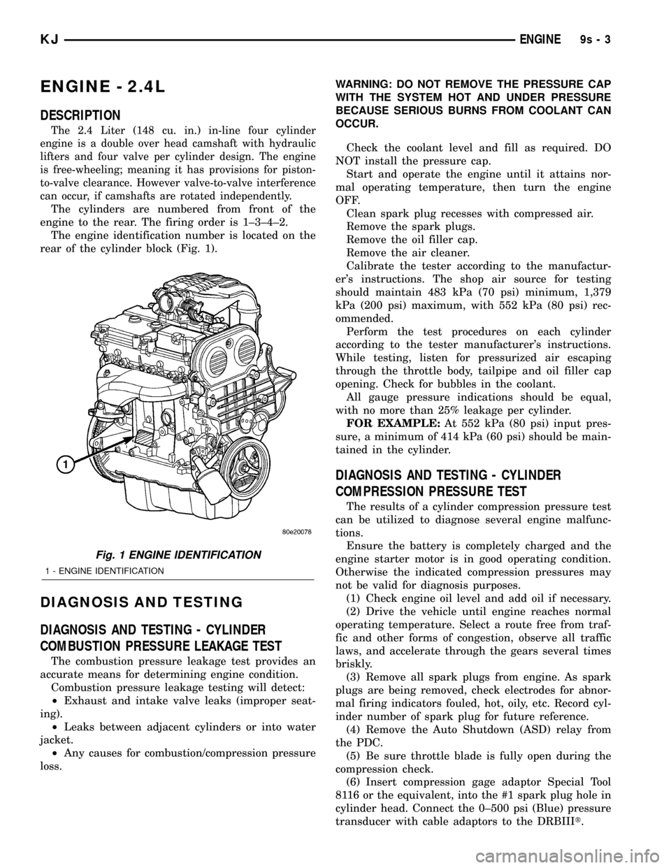
The engine identification number is located on the
rear of the cylinder block (Fig. 1).
DIAGNOSIS AND TESTING
DIAGNOSIS AND TESTING - CYLINDER
COMBUSTION PRESSURE LEAKAGE TEST
The combustion pressure leakage test provides an
accurate means for determining engine condition.
Combustion pressure leakage testing will detect:
²Exhaust and intake valve leaks (improper seat-
ing).
²Leaks between adjacent cylinders or into water
jacket.
²Any causes for combustion/compression pressure
loss.WARNING: DO NOT REMOVE THE PRESSURE CAP
WITH THE SYSTEM HOT AND UNDER PRESSURE
BECAUSE SERIOUS BURNS FROM COOLANT CAN
OCCUR.
Check the coolant level and fill as required. DO
NOT install the pressure cap.
Start and operate the engine until it attains nor-
mal operating temperature, then turn the engine
OFF.
Clean spark plug recesses with compressed air.
Remove the spark plugs.
Remove the oil filler cap.
Remove the air cleaner.
Calibrate the tester according to the manufactur-
er's instructions. The shop air source for testing
should maintain 483 kPa (70 psi) minimum, 1,379
kPa (200 psi) maximum, with 552 kPa (80 psi) rec-
ommended.
Perform the test procedures on each cylinder
according to the tester manufacturer's instructions.
While testing, listen for pressurized air escaping
through the throttle body, tailpipe and oil filler cap
opening. Check for bubbles in the coolant.
All gauge pressure indications should be equal,
with no more than 25% leakage per cylinder.
FOR EXAMPLE:At 552 kPa (80 psi) input pres-
sure, a minimum of 414 kPa (60 psi) should be main-
tained in the cylinder.
DIAGNOSIS AND TESTING - CYLINDER
COMPRESSION PRESSURE TEST
The results of a cylinder compression pressure test
can be utilized to diagnose several engine malfunc-
tions.
Ensure the battery is completely charged and the
engine starter motor is in good operating condition.
Otherwise the indicated compression pressures may
not be valid for diagnosis purposes.
(1) Check engine oil level and add oil if necessary.
(2) Drive the vehicle until engine reaches normal
operating temperature. Select a route free from traf-
fic and other forms of congestion, observe all traffic
laws, and accelerate through the gears several times
briskly.
(3) Remove all spark plugs from engine. As spark
plugs are being removed, check electrodes for abnor-
mal firing indicators fouled, hot, oily, etc. Record cyl-
inder number of spark plug for future reference.
(4) Remove the Auto Shutdown (ASD) relay from
the PDC.
(5) Be sure throttle blade is fully open during the
compression check.
(6) Insert compression gage adaptor Special Tool
8116 or the equivalent, into the #1 spark plug hole in
cylinder head. Connect the 0±500 psi (Blue) pressure
transducer with cable adaptors to the DRBIIIt.
Fig. 1 ENGINE IDENTIFICATION
1 - ENGINE IDENTIFICATION
KJENGINE9s-3
Page 1304 of 1803
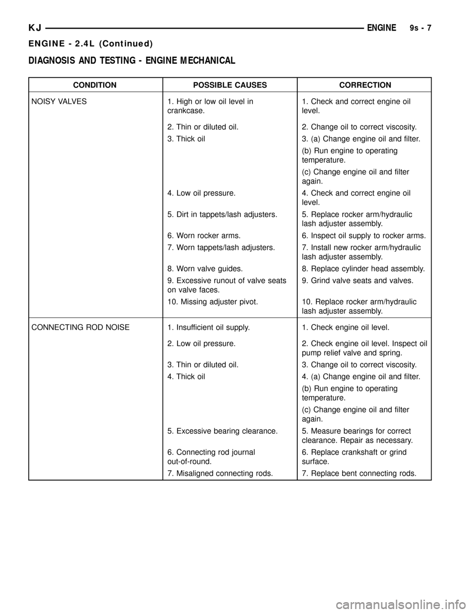
DIAGNOSIS AND TESTING - ENGINE MECHANICAL
CONDITION POSSIBLE CAUSES CORRECTION
NOISY VALVES 1. High or low oil level in
crankcase.1. Check and correct engine oil
level.
2. Thin or diluted oil. 2. Change oil to correct viscosity.
3. Thick oil 3. (a) Change engine oil and filter.
(b) Run engine to operating
temperature.
(c) Change engine oil and filter
again.
4. Low oil pressure. 4. Check and correct engine oil
level.
5. Dirt in tappets/lash adjusters. 5. Replace rocker arm/hydraulic
lash adjuster assembly.
6. Worn rocker arms. 6. Inspect oil supply to rocker arms.
7. Worn tappets/lash adjusters. 7. Install new rocker arm/hydraulic
lash adjuster assembly.
8. Worn valve guides. 8. Replace cylinder head assembly.
9. Excessive runout of valve seats
on valve faces.9. Grind valve seats and valves.
10. Missing adjuster pivot. 10. Replace rocker arm/hydraulic
lash adjuster assembly.
CONNECTING ROD NOISE 1. Insufficient oil supply. 1. Check engine oil level.
2. Low oil pressure. 2. Check engine oil level. Inspect oil
pump relief valve and spring.
3. Thin or diluted oil. 3. Change oil to correct viscosity.
4. Thick oil 4. (a) Change engine oil and filter.
(b) Run engine to operating
temperature.
(c) Change engine oil and filter
again.
5. Excessive bearing clearance. 5. Measure bearings for correct
clearance. Repair as necessary.
6. Connecting rod journal
out-of-round.6. Replace crankshaft or grind
surface.
7. Misaligned connecting rods. 7. Replace bent connecting rods.
KJENGINE9s-7
ENGINE - 2.4L (Continued)
Page 1305 of 1803
CONDITION POSSIBLE CAUSES CORRECTION
MAIN BEARING NOISE 1. Insufficient oil supply. 1. Check engine oil level.
2. Low oil pressure. 2. Check engine oil level. Inspect oil
pump relief valve and spring.
3. Thin or diluted oil. 3. Change oil to correct viscosity.
4. Thick oil 4. (a) Change engine oil and filter.
(b) Run engine to operating
temperature.
(c) Change engine oil and filter
again.
5. Excessive bearing clearance. 5. Measure bearings for correct
clearance. Repair as necessary.
6. Excessive end play. 6. Check thrust bearing for wear on
flanges.
7. Crankshaft journal out-of-round
or worn.7. Replace crankshaft or grind
journals.
8. Loose flywheel or torque
converter.8. Tighten to correct torque.
OIL PRESSURE DROP 1. Low oil level. 1. Check engine oil level.
2. Faulty oil pressure sending unit. 2. Install new sending unit.
3. Low oil pressure. 3. Check sending unit and main
bearing oil clearance.
4. Clogged oil filter. 4. Install new oil filter.
5. Worn parts in oil pump. 5. Replace worn parts or pump.
6. Thin or diluted oil. 6. Change oil to correct viscosity.
7. Oil pump relief valve stuck. 7. Replace oil pump.
8. Oil pump suction tube loose. 8. Remove oil pan and install new
tube or clean, if necessary.
9. Oil pump cover warped or
cracked.9. Install new oil pump.
10. Excessive bearing clearance. 10. Measure bearings for correct
clearance.
OIL LEAKS 1. Misaligned or deteriorated
gaskets.1. Replace gasket(s).
2. Loose fastener, broken or porous
metal part.2. Tighten, repair or replace the
part.
3. Misaligned or deteriorated cup or
threaded plug.3. Replace as necessary.
9s - 8 ENGINEKJ
ENGINE - 2.4L (Continued)
Page 1325 of 1803
INSPECTION
(1) Whenever valves have been removed for inspec-
tion, reconditioning or replacement, valve springs
should be tested for correct tension. Discard the
springs that do not meet specifications. The following
specifications apply to both intake and exhaust
valves springs:
²Valve Closed Nominal TensionÐ76 lbs. @ 38.0
mm (1.50 in.)
²Valve Open Nominal TensionÐ136 lbs. @ 29.75
mm (1.17 in.)
(2) Inspect each valve spring for squareness with a
steel square and surface plate, test springs from both
ends. If the spring is more than 1.5 mm (1/16 inch)
out of square, install a new spring.
INSTALLATION
INSTALLATION - CYLINDER HEAD ON
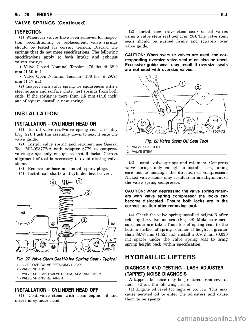
(1) Install valve seal/valve spring seat assembly
(Fig. 27). Push the assembly down to seat it onto the
valve guide.
(2) Install valve spring and retainer, use Special
Tool MD-998772-A with adapter 6779 to compress
valve springs only enough to install locks. Correct
alignment of tool is necessary to avoid nicking valve
stems.
(3) Remove air hose and install spark plugs.
(4) Install camshafts and cylinder head cover .
INSTALLATION - CYLINDER HEAD OFF
(1) Coat valve stems with clean engine oil and
insert in cylinder head.(2) Install new valve stem seals on all valves
using a valve stem seal tool (Fig. 28). The valve stem
seals should be pushed firmly and squarely over
valve guide.
CAUTION: When oversize valves are used, the cor-
responding oversize valve seal must also be used.
Excessive guide wear may result if oversize seals
are not used with oversize valves.
(3) Install valve springs and retainers. Compress
valve springs only enough to install locks, taking
care not to misalign the direction of compression.
Nicked valve stems may result from misalignment of
the valve spring compressor.
CAUTION: When depressing the valve spring retain-
ers with valve spring compressor the locks can
become dislocated. Ensure both locks are in the
correct location after removing tool.
(4) Check the valve spring installed height B after
refacing the valve and seat (Fig. 29). Make sure mea-
surements are taken from top of spring seat to the
bottom surface of spring retainer. If height is greater
than 38.75 mm (1.525 in.), install a 0.762 mm (0.030
in.) spacer under the valve spring seat to bring
spring height back within specification.
HYDRAULIC LIFTERS
DIAGNOSIS AND TESTING - LASH ADJUSTER
(TAPPET) NOISE DIAGNOSIS
A tappet-like noise may be produced from several
items. Check the following items.
(1) Engine oil level too high or too low. This may
cause aerated oil to enter the adjusters and cause
them to be spongy.
Fig. 27 Valve Stem Seal/Valve Spring Seat - Typical
1 - 3-GROOVE -VALVE RETAINING LOCKS
2 - VALVE SPRING
3 - VALVE SEAL AND VALVE SPRING SEAT ASSEMBLY
4 - VALVE SPRING RETAINER
Fig. 28 Valve Stem Oil Seal Tool
1 - VALVE SEAL TOOL
2 - VALVE STEM
9s - 28 ENGINEKJ
VALVE SPRINGS (Continued)
Page 1329 of 1803
INSPECTION
ENGINE BLOCK
(1) Clean cylinder block thoroughly and check all
core hole plugs for evidence of leaking.
(2) If new core plugs are to be installed, (Refer to 9
- ENGINE - STANDARD PROCEDURE - ENGINE
CORE AND OIL GALLERY PLUGS).
(3) Examine block and cylinder bores for cracks or
fractures.
(4) Check block deck surfaces for flatness. Deck
surface must be within service limit of 0.1 mm (0.004
in.).
CYLINDER BORE
NOTE: The cylinder bores should be measured at
normal room temperature, 21ÉC (70ÉF).
The cylinder walls should be checked for out-of-
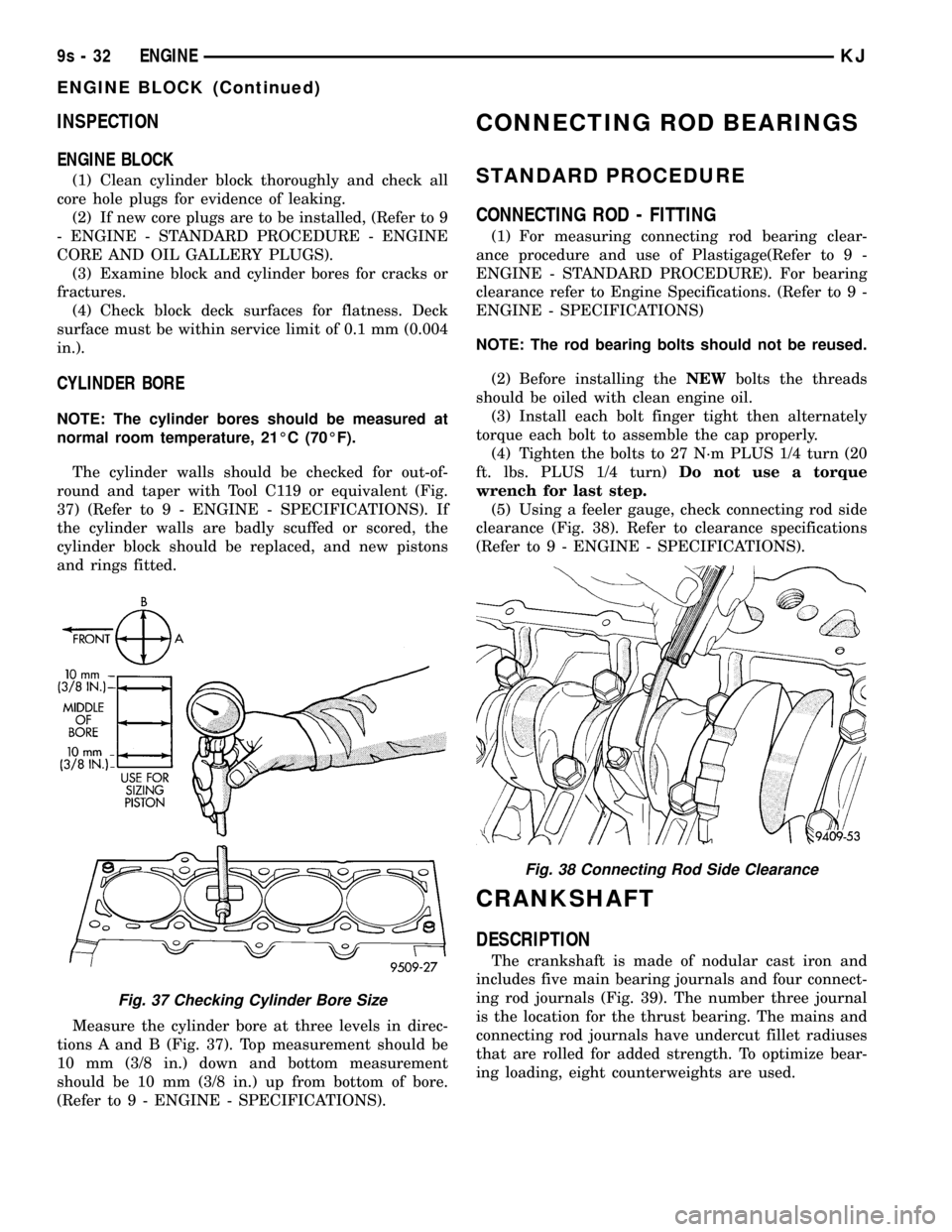
round and taper with Tool C119 or equivalent (Fig.
37) (Refer to 9 - ENGINE - SPECIFICATIONS). If
the cylinder walls are badly scuffed or scored, the
cylinder block should be replaced, and new pistons
and rings fitted.
Measure the cylinder bore at three levels in direc-
tions A and B (Fig. 37). Top measurement should be
10 mm (3/8 in.) down and bottom measurement
should be 10 mm (3/8 in.) up from bottom of bore.
(Refer to 9 - ENGINE - SPECIFICATIONS).
CONNECTING ROD BEARINGS
STANDARD PROCEDURE
CONNECTING ROD - FITTING
(1) For measuring connecting rod bearing clear-
ance procedure and use of Plastigage(Refer to 9 -
ENGINE - STANDARD PROCEDURE). For bearing
clearance refer to Engine Specifications. (Refer to 9 -
ENGINE - SPECIFICATIONS)
NOTE: The rod bearing bolts should not be reused.
(2) Before installing theNEWbolts the threads
should be oiled with clean engine oil.
(3) Install each bolt finger tight then alternately
torque each bolt to assemble the cap properly.
(4) Tighten the bolts to 27 N´m PLUS 1/4 turn (20
ft. lbs. PLUS 1/4 turn)Do not use a torque
wrench for last step.
(5) Using a feeler gauge, check connecting rod side
clearance (Fig. 38). Refer to clearance specifications
(Refer to 9 - ENGINE - SPECIFICATIONS).
CRANKSHAFT
DESCRIPTION
The crankshaft is made of nodular cast iron and
includes five main bearing journals and four connect-
ing rod journals (Fig. 39). The number three journal
is the location for the thrust bearing. The mains and
connecting rod journals have undercut fillet radiuses
that are rolled for added strength. To optimize bear-
ing loading, eight counterweights are used.
Fig. 37 Checking Cylinder Bore Size
Fig. 38 Connecting Rod Side Clearance
9s - 32 ENGINEKJ
ENGINE BLOCK (Continued)
Page 1344 of 1803
(6) Install oil pressure switch and connector. (Refer
to 9 - ENGINE/LUBRICATION/OIL PRESSURE
SENSOR/SWITCH - INSTALLATION)
OIL
STANDARD PROCEDURE
ENGINE OIL LEVEL CHECK
The best time to check engine oil level is after it
has sat overnight, or if the engine has been running,
allow the engine to be shut off for at least 5 minutes
before checking oil level.
Checking the oil while the vehicle is on level
ground will improve the accuracy of the oil level
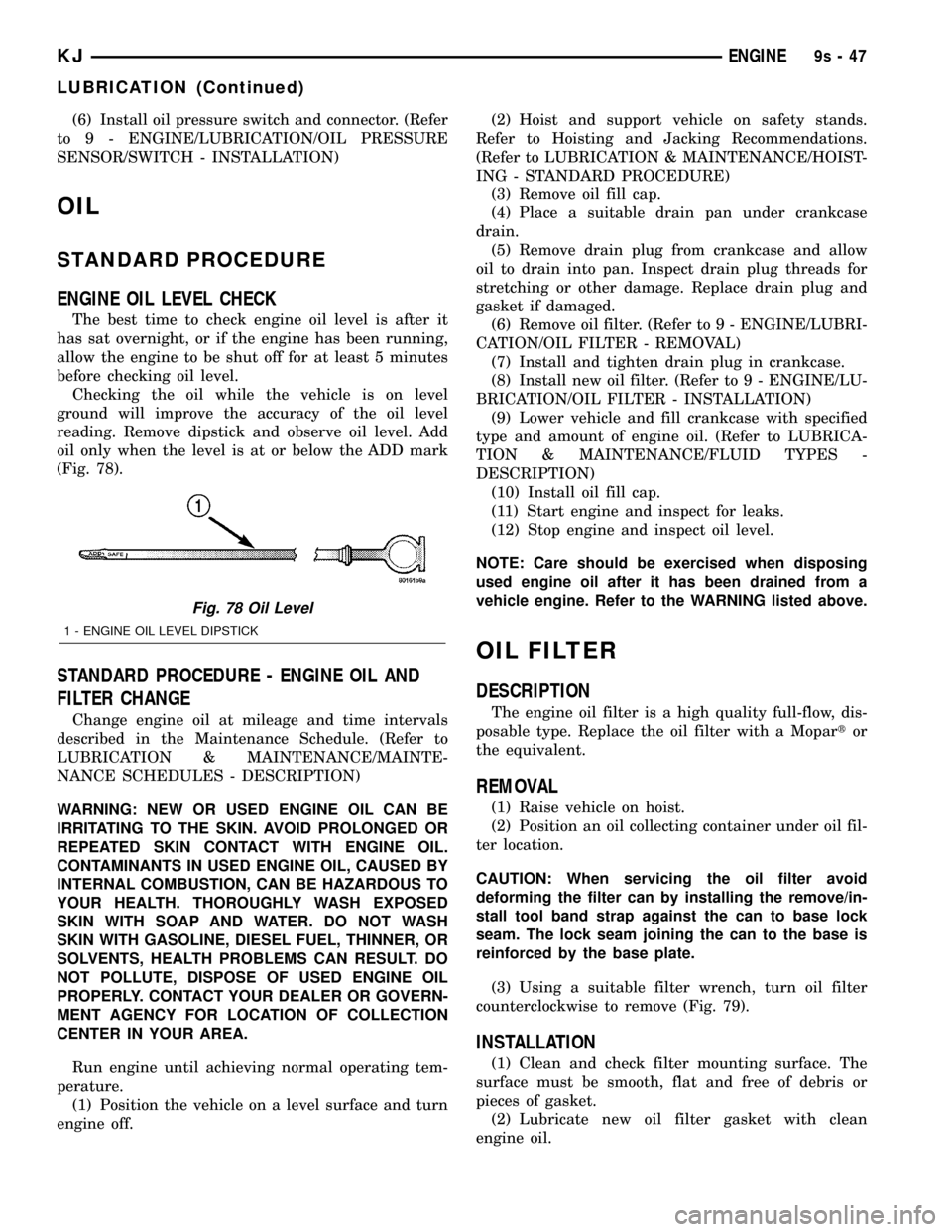
reading. Remove dipstick and observe oil level. Add
oil only when the level is at or below the ADD mark
(Fig. 78).
STANDARD PROCEDURE - ENGINE OIL AND
FILTER CHANGE
Change engine oil at mileage and time intervals
described in the Maintenance Schedule. (Refer to
LUBRICATION & MAINTENANCE/MAINTE-
NANCE SCHEDULES - DESCRIPTION)
WARNING: NEW OR USED ENGINE OIL CAN BE
IRRITATING TO THE SKIN. AVOID PROLONGED OR
REPEATED SKIN CONTACT WITH ENGINE OIL.
CONTAMINANTS IN USED ENGINE OIL, CAUSED BY
INTERNAL COMBUSTION, CAN BE HAZARDOUS TO
YOUR HEALTH. THOROUGHLY WASH EXPOSED
SKIN WITH SOAP AND WATER. DO NOT WASH
SKIN WITH GASOLINE, DIESEL FUEL, THINNER, OR
SOLVENTS, HEALTH PROBLEMS CAN RESULT. DO
NOT POLLUTE, DISPOSE OF USED ENGINE OIL
PROPERLY. CONTACT YOUR DEALER OR GOVERN-
MENT AGENCY FOR LOCATION OF COLLECTION
CENTER IN YOUR AREA.
Run engine until achieving normal operating tem-
perature.
(1) Position the vehicle on a level surface and turn
engine off.(2) Hoist and support vehicle on safety stands.
Refer to Hoisting and Jacking Recommendations.
(Refer to LUBRICATION & MAINTENANCE/HOIST-
ING - STANDARD PROCEDURE)
(3) Remove oil fill cap.
(4) Place a suitable drain pan under crankcase
drain.
(5) Remove drain plug from crankcase and allow
oil to drain into pan. Inspect drain plug threads for
stretching or other damage. Replace drain plug and
gasket if damaged.
(6) Remove oil filter. (Refer to 9 - ENGINE/LUBRI-
CATION/OIL FILTER - REMOVAL)
(7) Install and tighten drain plug in crankcase.
(8) Install new oil filter. (Refer to 9 - ENGINE/LU-
BRICATION/OIL FILTER - INSTALLATION)
(9) Lower vehicle and fill crankcase with specified
type and amount of engine oil. (Refer to LUBRICA-
TION & MAINTENANCE/FLUID TYPES -
DESCRIPTION)
(10) Install oil fill cap.
(11) Start engine and inspect for leaks.
(12) Stop engine and inspect oil level.
NOTE: Care should be exercised when disposing
used engine oil after it has been drained from a
vehicle engine. Refer to the WARNING listed above.
OIL FILTER
DESCRIPTION
The engine oil filter is a high quality full-flow, dis-
posable type. Replace the oil filter with a Mopartor
the equivalent.
REMOVAL
(1) Raise vehicle on hoist.
(2) Position an oil collecting container under oil fil-
ter location.
CAUTION: When servicing the oil filter avoid
deforming the filter can by installing the remove/in-
stall tool band strap against the can to base lock
seam. The lock seam joining the can to the base is
reinforced by the base plate.
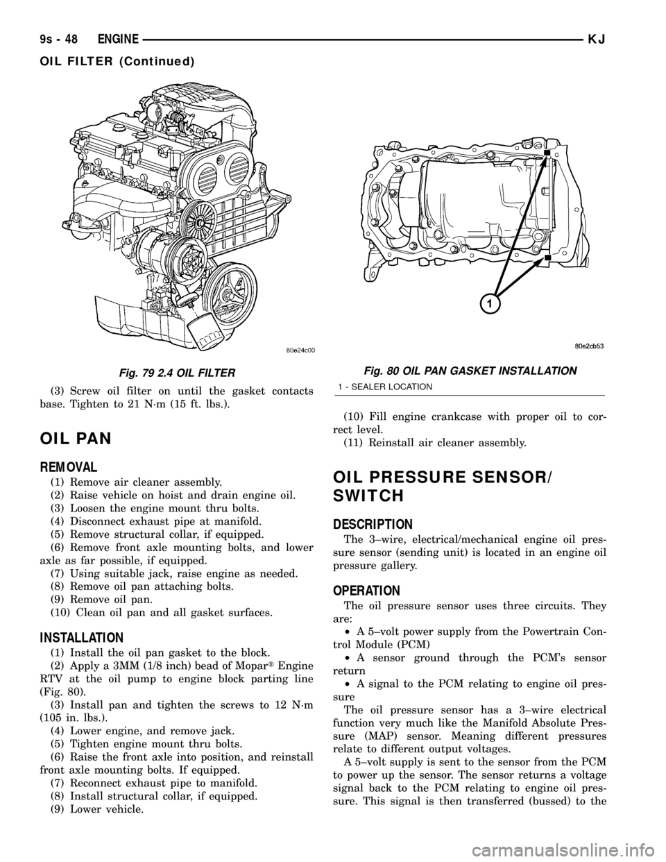
(3) Using a suitable filter wrench, turn oil filter
counterclockwise to remove (Fig. 79).
INSTALLATION
(1) Clean and check filter mounting surface. The
surface must be smooth, flat and free of debris or
pieces of gasket.
(2) Lubricate new oil filter gasket with clean
engine oil.
Fig. 78 Oil Level
1 - ENGINE OIL LEVEL DIPSTICK
KJENGINE9s-47
LUBRICATION (Continued)
Page 1345 of 1803
(3) Screw oil filter on until the gasket contacts
base. Tighten to 21 N´m (15 ft. lbs.).
OIL PAN
REMOVAL
(1) Remove air cleaner assembly.
(2) Raise vehicle on hoist and drain engine oil.
(3) Loosen the engine mount thru bolts.
(4) Disconnect exhaust pipe at manifold.
(5) Remove structural collar, if equipped.
(6) Remove front axle mounting bolts, and lower
axle as far possible, if equipped.
(7) Using suitable jack, raise engine as needed.
(8) Remove oil pan attaching bolts.
(9) Remove oil pan.
(10) Clean oil pan and all gasket surfaces.
INSTALLATION
(1) Install the oil pan gasket to the block.
(2) Apply a 3MM (1/8 inch) bead of MopartEngine
RTV at the oil pump to engine block parting line
(Fig. 80).
(3) Install pan and tighten the screws to 12 N´m
(105 in. lbs.).
(4) Lower engine, and remove jack.
(5) Tighten engine mount thru bolts.
(6) Raise the front axle into position, and reinstall
front axle mounting bolts. If equipped.
(7) Reconnect exhaust pipe to manifold.
(8) Install structural collar, if equipped.
(9) Lower vehicle.(10) Fill engine crankcase with proper oil to cor-
rect level.
(11) Reinstall air cleaner assembly.
OIL PRESSURE SENSOR/
SWITCH
DESCRIPTION
The 3±wire, electrical/mechanical engine oil pres-
sure sensor (sending unit) is located in an engine oil
pressure gallery.
OPERATION
The oil pressure sensor uses three circuits. They
are:
²A 5±volt power supply from the Powertrain Con-
trol Module (PCM)
²A sensor ground through the PCM's sensor
return
²A signal to the PCM relating to engine oil pres-
sure
The oil pressure sensor has a 3±wire electrical
function very much like the Manifold Absolute Pres-
sure (MAP) sensor. Meaning different pressures
relate to different output voltages.
A 5±volt supply is sent to the sensor from the PCM
to power up the sensor. The sensor returns a voltage
signal back to the PCM relating to engine oil pres-
sure. This signal is then transferred (bussed) to the
Fig. 79 2.4 OIL FILTERFig. 80 OIL PAN GASKET INSTALLATION
1 - SEALER LOCATION
9s - 48 ENGINEKJ
OIL FILTER (Continued)