2002 JEEP LIBERTY 9 Engine
[x] Cancel search: 9 EnginePage 1429 of 1803

THROTTLE POSITION SENSOR
DESCRIPTION
The 3±wire Throttle Position Sensor (TPS) is
mounted on the throttle body and is connected to the
throttle blade shaft.
OPERATION
The 3±wire TPS provides the Powertrain Control
Module (PCM) with an input signal (voltage) that
represents the throttle blade position of the throttle
body. The sensor is connected to the throttle blade
shaft. As the position of the throttle blade changes,
the output voltage of the TPS changes.
The PCM supplies approximately 5 volts to the
TPS. The TPS output voltage (input signal to the
PCM) represents the throttle blade position. The
PCM receives an input signal voltage from the TPS.
This will vary in an approximate range of from .26
volts at minimum throttle opening (idle), to 4.49 volts
at wide open throttle. Along with inputs from other
sensors, the PCM uses the TPS input to determine
current engine operating conditions. In response to
engine operating conditions, the PCM will adjust fuel
injector pulse width and ignition timing.
The PCM needs to identify the actions and position
of the throttle blade at all times. This information is
needed to assist in performing the following calcula-
tions:
²Ignition timing advance
²Fuel injection pulse-width
²Idle (learned value or minimum TPS)
²Off-idle (0.06 volt)
²Wide Open Throttle (WOT) open loop (2.608
volts above learned idle voltage)
²Deceleration fuel lean out
²Fuel cutoff during cranking at WOT (2.608 volts
above learned idle voltage)
²A/C WOT cutoff (certain automatic transmis-
sions only)
REMOVAL
2.4L
The Throttle Position Sensor (TPS) is mounted to
the throttle body (Fig. 31).
(1) Disconnect TPS electrical connector.
(2) Remove 2 TPS mounting screws.
(3) Remove TPS.
Fig. 31 TPS/IAC MOTOR - 2.4L
1 - THROTTLE POSITION SENSOR (TPS)
2 - MOUNTING SCREWS
3 - IDLE AIR CONTROL MOTOR (IAC)
4 - MOUNTING SCREWS
KJFUEL INJECTION 14 - 47
Page 1430 of 1803

3.7L
The Throttle Position Sensor (TPS) is mounted to
the throttle body (Fig. 32), or (Fig. 33).
(1) Disconnect TPS electrical connector.
(2) Remove 2 TPS mounting screws.
(3) Remove TPS.
INSTALLATION
2.4L
The Throttle Position Sensor (TPS) is mounted to
the rear of the throttle body.
The throttle shaft end of the throttle body slides
into a socket in the TPS (Fig. 33). The TPS must be
installed so that it can be rotated a few degrees. (If
sensor will not rotate, install sensor with throttle
shaft on other side of socket tangs). The TPS will be
under slight tension when rotated.
(1) Install TPS and retaining screws.
(2) Tighten screws to 7 N´m (60 in. lbs.) torque.
(3) Connect TPS electrical connector to TPS.(4) Manually operate throttle (by hand) to check
for any TPS binding before starting engine.
(5) Install air cleaner tube to throttle body.
3.7L
The Throttle Position Sensor (TPS) is mounted to
the throttle body (Fig. 32).
The throttle shaft end of the throttle body slides
into a socket in the TPS (Fig. 33). The TPS must be
installed so that it can be rotated a few degrees. (If
sensor will not rotate, install sensor with throttle
shaft on other side of socket tangs). The TPS will be
under slight tension when rotated.
(1) Install TPS and retaining screws.
(2) Tighten screws to 7 N´m (60 in. lbs.) torque.
(3) Connect TPS electrical connector to TPS.
(4) Manually operate throttle (by hand) to check
for any TPS binding before starting engine.
(5) Install air cleaner tube to throttle body.
Fig. 32 TPS/IAC MOTOR - 3.7L
1 - THROTTLE POSITION SENSOR (TPS)
2 - MOUNTING SCREWS
3 - IDLE AIR CONTROL MOTOR (IAC)
4 - MOUNTING SCREWS
Fig. 33 TPS INSTALLATION - 3.7
1 - THROTTLE BODY
2 - TPS
3 - THROTTLE BODY SHAFT
4 - SOCKET LOCATING TANGS
14 - 48 FUEL INJECTIONKJ
THROTTLE POSITION SENSOR (Continued)
Page 1431 of 1803

STEERING
TABLE OF CONTENTS
page page
STEERING
DESCRIPTION..........................1
OPERATION............................1
DIAGNOSIS AND TESTING
DIAGNOSIS AND TESTING - POWER
STEERING SYSTEM....................1DIAGNOSIS AND TESTING - POWER
STEERING FLOW AND PRESSURE........3
COLUMN...............................5
GEAR.................................13
LINKAGE..............................16
PUMP.................................17
STEERING
DESCRIPTION
Power steering systems consist of:
²Steering column & Intermediate Shaft
²Rack and pinion steering gear
²Belt driven hydraulic steering pump
²Pump pressure, supply and return hoses
²Oil Cooler
OPERATION
The steering column intermediate shaft attaches
the steering column to the gear pinion. The rotation
of the pinion moves the gear rack from side-to-side.
This lateral action of the rack pushes and pulls the
tie rods to change the direction of the front wheels.
Power assist is provided by an engine mounted
hydraulic pump. The pump supplies hydraulic fluid
to the steering gear. All vehicles are equipped with
an oil cooler.
DIAGNOSIS AND TESTING
DIAGNOSIS AND TESTING - POWER STEERING SYSTEM
STEERING NOISE
There is some noise in all power steering systems. One of the most common is a hissing sound evident at a
standstill/parking, or when the steering is at the end of it's travel. Hiss is a high frequency noise similar to that
of a water tap being closed slowly. The noise is present in all valves that have a high velocity fluid passing through
an orifice. There is no relationship between this noise and steering performance.
CONDITION POSSIBLE CAUSES CORRECTION
OBJECTIONAL HISS OR
WHISTLE1. Steering intermediate shaft to dash panel
seal.1. Check and repair seal at dash
panel.
2. Noisy valve in power steering gear. 2. Replace steering gear.
1. Gear mounting bolts loose. 1. Tighten bolts to specification.
2. Loose or damaged suspension
components.2. Inspect and repair suspension.
3. Internal gear noise. 3. Replace steering gear.
4. Loose or damaged intermediate shaft or
column.4. Inspect and repair or replace.
MOAN Pressure hose in contact with other
components.Reposition hose.
CHIRP OR SQUEAL 1. Loose belt. 1. Adjust or replace.
KJSTEERING 19 - 1
Page 1433 of 1803

LOOSE STEERING AND VEHICLE LEAD
CONDITION POSSIBLE CAUSE CORRECTION
EXCESSIVE PLAY IN STEERING
WHEEL1. Worn or loose suspension or
steering components.1. Inspect and repair as necessary.
2. Worn or loose wheel bearings. 2. Inspect and replace bearings.
3. Steering gear mounting. 3. Tighten / replace gear mounting
bolts/ isolators to specification.
4. Gear out of adjustment. 4. Replace gear.
5. Worn or loose steering
intermediate shaft.5. Inspect and replace as
necessary.
VEHICLE PULLS, DRIFTS OR
LEADS TO ONE SIDE.1. Tire Pressure. 1. Adjust tire pressure.
2. Radial tire lead. 2. Rotate tires.
3. Brakes dragging. 3. Repair as necessary.
4. Wheel alignment. 4. Align front end.
DIAGNOSIS AND TESTING - POWER STEERING
FLOW AND PRESSURE
The following procedure is used to test the opera-
tion of the power steering system on the vehicle. This
test will provide the gallons per minute (GPM) or
flow rate of the power steering pump along with the
maximum relief pressure. Perform test any time a
power steering system problem is present. This test
will determine if the power steering pump or power
steering gear is not functioning properly. The follow-
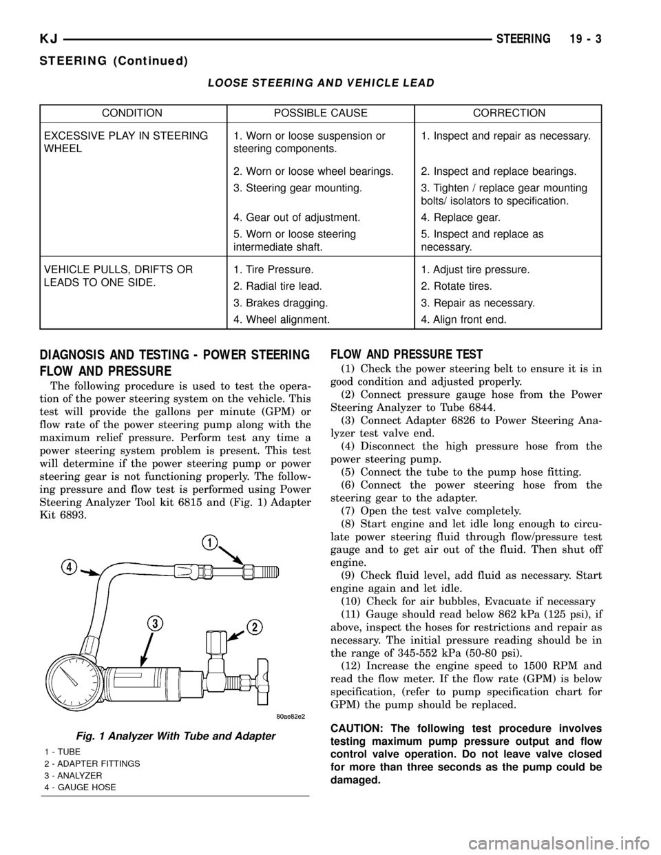
ing pressure and flow test is performed using Power
Steering Analyzer Tool kit 6815 and (Fig. 1) Adapter
Kit 6893.
FLOW AND PRESSURE TEST
(1) Check the power steering belt to ensure it is in
good condition and adjusted properly.
(2) Connect pressure gauge hose from the Power
Steering Analyzer to Tube 6844.
(3) Connect Adapter 6826 to Power Steering Ana-
lyzer test valve end.
(4) Disconnect the high pressure hose from the
power steering pump.
(5) Connect the tube to the pump hose fitting.
(6) Connect the power steering hose from the
steering gear to the adapter.
(7) Open the test valve completely.
(8) Start engine and let idle long enough to circu-
late power steering fluid through flow/pressure test
gauge and to get air out of the fluid. Then shut off
engine.
(9) Check fluid level, add fluid as necessary. Start
engine again and let idle.
(10) Check for air bubbles, Evacuate if necessary
(11) Gauge should read below 862 kPa (125 psi), if
above, inspect the hoses for restrictions and repair as
necessary. The initial pressure reading should be in
the range of 345-552 kPa (50-80 psi).
(12) Increase the engine speed to 1500 RPM and
read the flow meter. If the flow rate (GPM) is below
specification, (refer to pump specification chart for
GPM) the pump should be replaced.
CAUTION: The following test procedure involves
testing maximum pump pressure output and flow
control valve operation. Do not leave valve closed
for more than three seconds as the pump could be
damaged.
Fig. 1 Analyzer With Tube and Adapter
1 - TUBE
2 - ADAPTER FITTINGS
3 - ANALYZER
4 - GAUGE HOSE
KJSTEERING 19 - 3
STEERING (Continued)
Page 1434 of 1803

(13) Close valve fully three times and record high-
est pressure indicated each time.All three read-
ings must be above specifications and within
345 kPa (50 psi) of each other.
²Pressures above specifications but not within
345 kPa (50 psi) of each other, replace pump.
²Pressures within 345 kPa (50 psi) of each other
but below specifications, replace pump.
(14) Open the test valve and turn the steering
wheel to the extreme left and right positions three
times against the stops. Record the highest pressure
reading at each position. Compare readings to the
pump specifications chart. If pressures readings are
not within 50 psi of each other, the gear is leaking
internally and must be replaced.CAUTION: Do not force the pump to operate against
the stops for more than 2 to 3 seconds at a time
because, pump damage will result.
PUMP SPECIFICATION
ENGINERELIEF PRESSURE
50FLOW RATE
(GPM) AT 1500
RPM
3.7L,
2.4L &
2.5L10342 kPa (1450 psi) 2.4 - 2.8
19 - 4 STEERINGKJ
STEERING (Continued)
Page 1448 of 1803

NOTE: Power steering pumps have different pres-
sure rates and are not interchangeable with other
pumps.
STANDARD PROCEDURE - POWER STEERING
PUMP - INITIAL OPERATION
WARNING: THE FLUID LEVEL SHOULD BE
CHECKED WITH ENGINE OFF TO PREVENT INJURY
FROM MOVING COMPONENTS.
CAUTION: Use MOPAR Power Steering Fluid or
equivalent. Do not use automatic transmission fluid
and do not overfill.
Wipe filler cap clean, then check the fluid level.
The dipstick should indicateCOLDwhen the fluid is
at normal ambient temperature.
(1) Fill the pump fluid reservoir to the proper level
and let the fluid settle for at least two minutes.
(2) Raise the front wheels off the ground.
(3) Slowly turn the steering wheel right and left,
lightly contacting the wheel stops at least 20 times.
(4) Check the fluid level add if necessary.
(5) Lower the vehicle, start the engine and turn
the steering wheel slowly from lock to lock.
(6) Stop the engine and check the fluid level and
refill as required.
CAUTION: Do not run a vehicle with foamy fluid for
an extended period. This may cause pump damage.
(7) If the fluid is extremely foamy or milky look-
ing, allow the vehicle to stand a few minutes and
repeat the procedure.
(8) Add fluid if necessary. Repeat the above proce-
dure until the fluid level remains constant after run-
ning the engine.
REMOVAL
REMOVAL - 3.7L
(1) Siphon out as much power steering fluid as
possible.
(2) Remove the radiator cross member (Refer to 23
- BODY/EXTERIOR/RADIATOR CROSSMEMBER -
REMOVAL).
(3) Remove the engine cooling fan (Refer to 7 -
COOLING/ENGINE/RADIATOR FAN - REMOVAL).
(4) Remove the fan shroud
(5) Remove the serpentine drive belt (Refer to 7 -
COOLING/ACCESSORY DRIVE/DRIVE BELTS -
REMOVAL).
(6) Remove the power steering high pressure hose
at the pump.
(7) Remove the return hose at the pump.
(8) Remove the three bolts securing the pump to
the bracket thru the holes in the pulley. (Fig. 3)
(9) Remove the pump from the vehicle.
REMOVAL - 2.4L
CAUTION: On vehicles equipped with the 2.4L, Do
not reuse the old power steering pump pulley it is
not intended for reuse. A new pulley must be
installed if removed.
(1) Siphon out as much power steering fluid as
possible.
(2) Remove the serpentine drive belt.
(3) Remove the power steering high pressure hose
at the pump using care not to remove the flow con-
trol valve.
(4) Remove the return hose at the pump.
Fig. 2 FLUID RESERVOIR - 2.4L
Fig. 3 POWER STEERING PUMP - 3.7L
1 - MOUNTING BOLTS
2 - RESERVOIR
3 - STEEL PULLEY
19 - 18 PUMPKJ
PUMP (Continued)
Page 1449 of 1803

(5) Remove the two nuts securing the wire loom
behind the pump bracket.
(6) Remove the three bolts securing the pump to
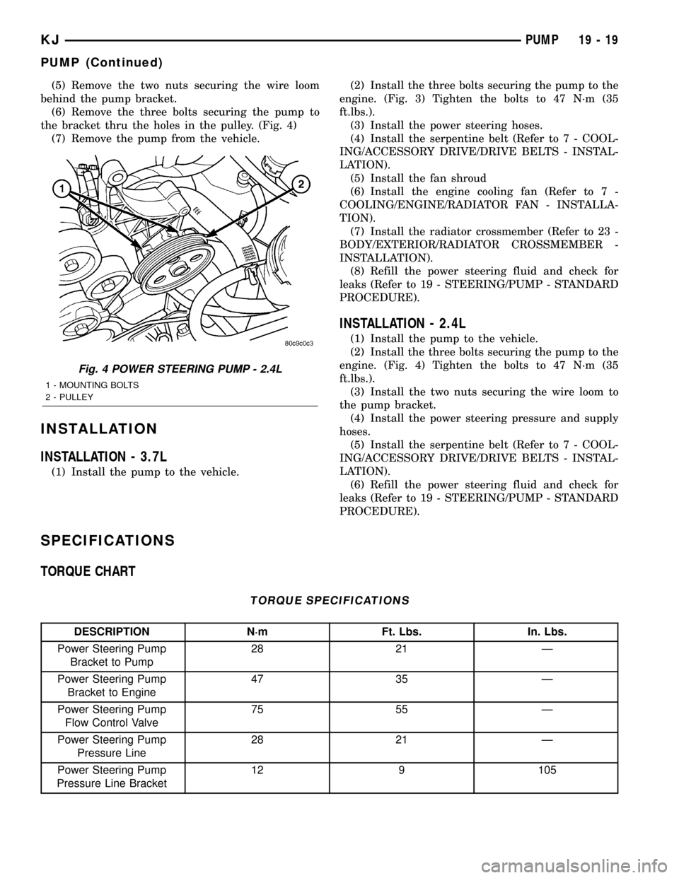
the bracket thru the holes in the pulley. (Fig. 4)
(7) Remove the pump from the vehicle.
INSTALLATION
INSTALLATION - 3.7L
(1) Install the pump to the vehicle.(2) Install the three bolts securing the pump to the
engine. (Fig. 3) Tighten the bolts to 47 N´m (35
ft.lbs.).
(3) Install the power steering hoses.
(4) Install the serpentine belt (Refer to 7 - COOL-
ING/ACCESSORY DRIVE/DRIVE BELTS - INSTAL-
LATION).
(5) Install the fan shroud
(6) Install the engine cooling fan (Refer to 7 -
COOLING/ENGINE/RADIATOR FAN - INSTALLA-
TION).
(7) Install the radiator crossmember (Refer to 23 -
BODY/EXTERIOR/RADIATOR CROSSMEMBER -
INSTALLATION).
(8) Refill the power steering fluid and check for
leaks (Refer to 19 - STEERING/PUMP - STANDARD
PROCEDURE).
INSTALLATION - 2.4L
(1) Install the pump to the vehicle.
(2) Install the three bolts securing the pump to the
engine. (Fig. 4) Tighten the bolts to 47 N´m (35
ft.lbs.).
(3) Install the two nuts securing the wire loom to
the pump bracket.
(4) Install the power steering pressure and supply
hoses.
(5) Install the serpentine belt (Refer to 7 - COOL-
ING/ACCESSORY DRIVE/DRIVE BELTS - INSTAL-
LATION).
(6) Refill the power steering fluid and check for
leaks (Refer to 19 - STEERING/PUMP - STANDARD
PROCEDURE).
SPECIFICATIONS
TORQUE CHART
TORQUE SPECIFICATIONS
DESCRIPTION N´m Ft. Lbs. In. Lbs.
Power Steering Pump
Bracket to Pump28 21 Ð
Power Steering Pump
Bracket to Engine47 35 Ð
Power Steering Pump
Flow Control Valve75 55 Ð
Power Steering Pump
Pressure Line28 21 Ð
Power Steering Pump
Pressure Line Bracket12 9 105
Fig. 4 POWER STEERING PUMP - 2.4L
1 - MOUNTING BOLTS
2 - PULLEY
KJPUMP 19 - 19
PUMP (Continued)
Page 1452 of 1803

(6) Install the serpentine belt (Refer to 7 - COOL-
ING/ACCESSORY DRIVE/DRIVE BELTS - INSTAL-
LATION).
(7) Install the fan shroud.
(8) Install the fan (Refer to 7 - COOLING/EN-
GINE/RADIATOR FAN - INSTALLATION).
(9) Install the radiator crossmember (Refer to 23 -
BODY/EXTERIOR/RADIATOR CROSSMEMBER -
INSTALLATION).
(10) Refill the power steering fluid (Refer to 19 -
STEERING/PUMP - STANDARD PROCEDURE).
INSTALLATION - RETURN HOSE (GEAR TO THE
COOLER)
(1) Install the return hose to the vehicle. (Fig. 7)
(2) Install the return hose mounting bracket bolts
to the front cradle.
(3) Install the return hose at the cooler.
(4) Install the return hose at the gear 28 N´m (21
ft.lbs.).
(5) Install the serpentine belt (Refer to 7 - COOL-
ING/ACCESSORY DRIVE/DRIVE BELTS - INSTAL-
LATION).
(6) Install the fan shroud.
(7) Install the fan (Refer to 7 - COOLING/EN-
GINE/RADIATOR FAN - INSTALLATION).
(8) Install the radiator crossmember (Refer to 23 -
BODY/EXTERIOR/RADIATOR CROSSMEMBER -
INSTALLATION).
(9) Refill the power steering fluid (Refer to 19 -
STEERING/PUMP - STANDARD PROCEDURE).
INSTALLATION - RETURN HOSE (RESERVOIR
TO THE COOLER)
(1) Install the return hose to the vehicle.
(2) Install the return hose to the pump reservoir.
(3) Install the return hose at the cooler.
(4) Refill the power steering fluid (Refer to 19 -
STEERING/PUMP - STANDARD PROCEDURE).
POWER STEERING PRESSURE
SWITCH
DESCRIPTION
A pressure sensing switch is used in the power
steering system. It is mounted on the high-pressure
steering hose. This switch will be used with both
2.4L and 3.7L engines.
OPERATION
The switch is used on both the 2.4L 4±cylinder and
3.7L V-6 engines.
The power steering pressure switch provides an
input to the Powertrain Control Module (PCM). This
input is provided during periods of high steering
pump load and low engine rpm; such as during park-
ing maneuvers. The PCM increases the idle speed
through the Idle Air Control (IAC) motor. This is
done to prevent the engine from stalling under the
increased load.
When steering pump pressure exceeds 3275 kPa
690 kPa (475 psi 100 psi), the Normally Closed
(NC) switch will open and the PCM will increase the
engine idle speed. This will prevent the engine from
stalling.
When pump pressure drops to approximately 1379
kPa (200 psi), the switch circuit will re-close and
engine idle speed will return to its previous setting.
REMOVAL
The power steering pressure switch is installed in
the power steering high-pressure hose (Fig. 9).
(1) Remove the high pressure power steering
hose(Refer to 19 - STEERING/PUMP/HOSES -
REMOVAL).
(2) Disconnect electrical connector from power
steering pressure switch.
(3) Place a small container or shop towel beneath
switch to collect any excess fluid.
(4) Remove switch. Use back-up wrench on power
steering line to prevent line bending.
INSTALLATION
(1) Install power steering switch into power steer-
ing line. (Fig. 9)
(2) Tighten to 9.6 N´m (85 in. lbs.) torque.
Fig. 8 HIGH PRESSURE HOSE ASSEMBLY
1 - HIGH PRESSURE POWER STEERING HOSE
2 - MOUNTING BRACKET
3 - POWER STEERING PRESURE SWITCH
19 - 22 PUMPKJ
HOSES (Continued)