2002 JEEP LIBERTY Timing
[x] Cancel search: TimingPage 1247 of 1803
INSPECTION
(1) Inspect the cylinder head for out-of-flatness,
using a straightedge and a feeler gauge. If measure-
ments exceed 0.0508 mm (0.002 in.) replace the cyl-
inder head.
(2) Inspect the valve seats for damage. Service the
valve seats as necessary.
(3) Inspect the valve guides for wear, cracks or
looseness. If either condition exist, replace the cylin-
der head.
INSTALLATION
NOTE: The cylinder head bolts are tightened using
a torque plus angle procedure. The bolts must be
examined BEFORE reuse. If the threads are necked
down the bolts should be replaced.
Necking can be checked by holding a straight edge
against the threads. If all the threads do not contact
the scale, the bolt should be replaced.
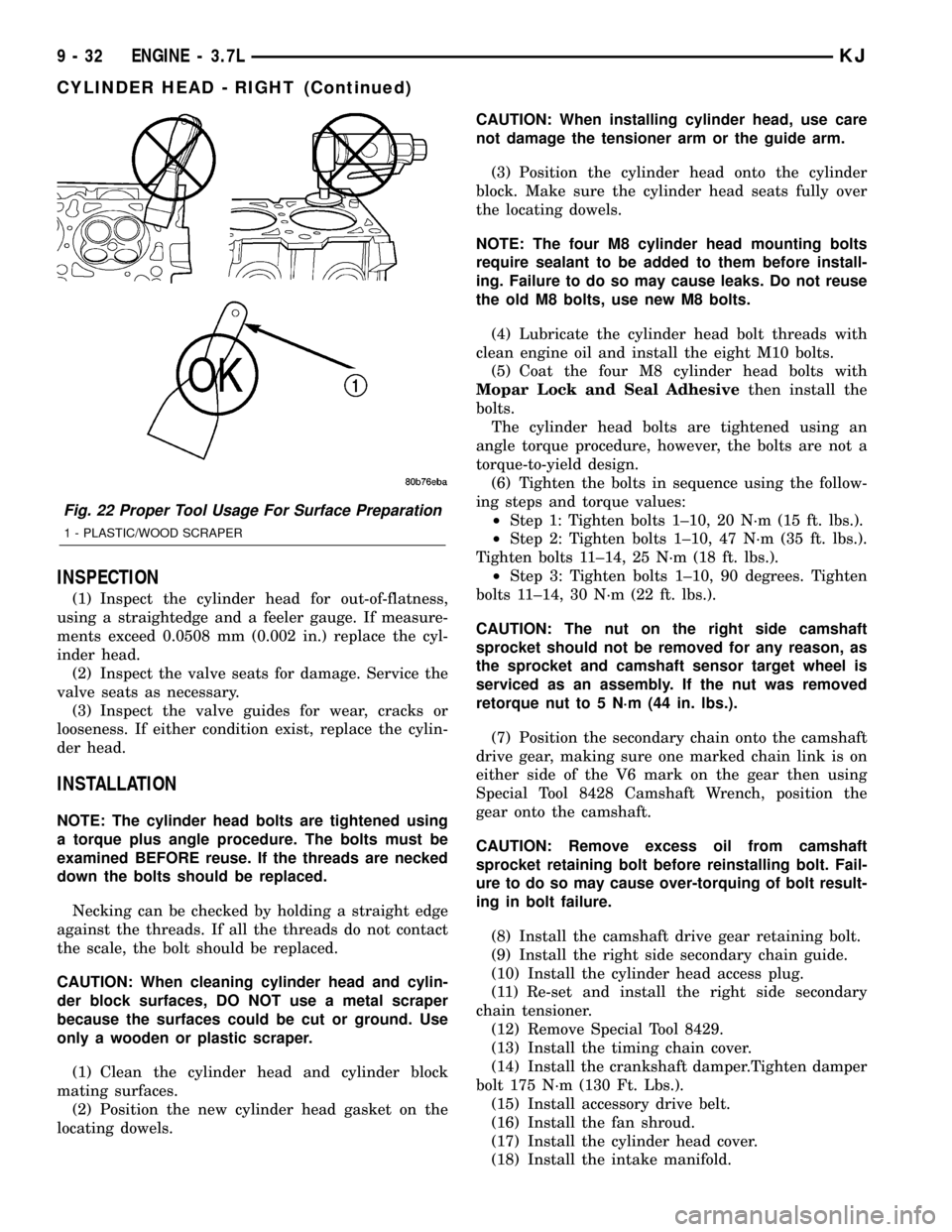
CAUTION: When cleaning cylinder head and cylin-
der block surfaces, DO NOT use a metal scraper
because the surfaces could be cut or ground. Use
only a wooden or plastic scraper.
(1) Clean the cylinder head and cylinder block
mating surfaces.
(2) Position the new cylinder head gasket on the
locating dowels.CAUTION: When installing cylinder head, use care
not damage the tensioner arm or the guide arm.
(3) Position the cylinder head onto the cylinder
block. Make sure the cylinder head seats fully over
the locating dowels.
NOTE: The four M8 cylinder head mounting bolts
require sealant to be added to them before install-
ing. Failure to do so may cause leaks. Do not reuse
the old M8 bolts, use new M8 bolts.
(4) Lubricate the cylinder head bolt threads with
clean engine oil and install the eight M10 bolts.
(5) Coat the four M8 cylinder head bolts with
Mopar Lock and Seal Adhesivethen install the
bolts.
The cylinder head bolts are tightened using an
angle torque procedure, however, the bolts are not a
torque-to-yield design.
(6) Tighten the bolts in sequence using the follow-
ing steps and torque values:
²Step 1: Tighten bolts 1±10, 20 N´m (15 ft. lbs.).
²Step 2: Tighten bolts 1±10, 47 N´m (35 ft. lbs.).
Tighten bolts 11±14, 25 N´m (18 ft. lbs.).
²Step 3: Tighten bolts 1±10, 90 degrees. Tighten
bolts 11±14, 30 N´m (22 ft. lbs.).
CAUTION: The nut on the right side camshaft
sprocket should not be removed for any reason, as
the sprocket and camshaft sensor target wheel is
serviced as an assembly. If the nut was removed
retorque nut to 5 N´m (44 in. lbs.).
(7) Position the secondary chain onto the camshaft
drive gear, making sure one marked chain link is on
either side of the V6 mark on the gear then using
Special Tool 8428 Camshaft Wrench, position the
gear onto the camshaft.
CAUTION: Remove excess oil from camshaft
sprocket retaining bolt before reinstalling bolt. Fail-
ure to do so may cause over-torquing of bolt result-
ing in bolt failure.
(8) Install the camshaft drive gear retaining bolt.
(9) Install the right side secondary chain guide.
(10) Install the cylinder head access plug.
(11) Re-set and install the right side secondary
chain tensioner.
(12) Remove Special Tool 8429.
(13) Install the timing chain cover.
(14) Install the crankshaft damper.Tighten damper
bolt 175 N´m (130 Ft. Lbs.).
(15) Install accessory drive belt.
(16) Install the fan shroud.
(17) Install the cylinder head cover.
(18) Install the intake manifold.
Fig. 22 Proper Tool Usage For Surface Preparation
1 - PLASTIC/WOOD SCRAPER
9 - 32 ENGINE - 3.7LKJ
CYLINDER HEAD - RIGHT (Continued)
Page 1248 of 1803
(19) Install oil fill housing onto cylinder head.
(20) Refill the cooling system.
(21) Raise the vehicle.
(22) Install the exhaust pipe onto the right
exhaust manifold.
(23) Lower the vehicle.
(24) Reconnect battery negitive cable.
(25) Start the engine and check for leaks.
CAMSHAFT(S)
DESCRIPTION
The camshafts consist of powdered metal steel
lobes which are sinter-bonded to a steel tube. Four
bearing journals are machined into the camshaft.
Camshaft end play is controlled by two thrust walls
that border the nose piece journal. Engine oil enters
the hollow camshafts at the third journal and lubri-
cates every intake lobe rocker through a drilled pas-
sage in the intake lobe.
REMOVAL
CAUTION: When the timing chain is removed and
the cylinder heads are still installed, DO NOT force-
fully rotate the camshafts or crankshaft indepen-
dently of each other. Severe valve and/or piston
damage can occur.
CAUTION: When removing the cam sprocket, timing
chains or camshaft, Failure to use special tool 8379
will result in hydraulic tensioner ratchet over exten-
sion, Requiring timing chain cover removal to re-set
the tensioner ratchet.
(1) Remove the cylinder head cover. Refer to CYL-
INDER HEAD COVER in this section.
(2) Set engine to TDC cylinder #1, camshaft
sprocket V6 marks at the 12 o'clock position.
(3) Mark one link on the secondary timing chain
on both sides of the V6 mark on the camshaft
sprocket to aid in installation.
CAUTION: Do not hold or pry on the camshaft tar-
get wheel for any reason, Severe damage will occur
to the target wheel. A damaged target wheel could
cause a vehicle no start condition.
(4) Loosen butDO NOTremove the camshaft
sprocket retaining bolt. Leave bolt snug against
sprocket.
NOTE: The timing chain tensioners must be
secured prior to removing the camshaft sprockets.
Failure to secure tensioners will allow the tension-ers to extend, requiring timing chain cover removal
in order to reset tensioners.
CAUTION: Do not force wedge past the narrowest
point between the chain strands. Damage to the
tensioners may occur.
(5) Position Special Tool 8379 timing chain wedge
between the timing chain strands. Tap the tool to
securely wedge the timing chain against the ten-
sioner arm and guide.
(6) Remove the camshaft position sensor.
(7) Hold the camshaft with Special Tool 8428 Cam-
shaft Wrench, while removing the camshaft sprocket
bolt and sprocket.
(8) Starting at the outside working inward, loosen
the camshaft bearing cap retaining bolts 1/2 turn at
a time. Repeat until all load is off the bearing caps.
CAUTION: DO NOT STAMP OR STRIKE THE CAM-
SHAFT BEARING CAPS. SEVERE DAMAGE WILL
OCCUR TO THE BEARING CAPS.
NOTE: When the camshaft is removed the rocker
arms may slide downward, mark the rocker arms
before removing camshaft.
(9) Remove the camshaft bearing caps and the
camshaft.
INSTALLATION
(1) Lubricate camshaft journals with clean engine
oil.
NOTE: Position the right side camshaft so that the
camshaft sprocket dowel is near the 10 o'clock
position, This will place the camshaft at the neutral
position easing the installation of the camshaft
bearing caps.
(2) Position the camshaft into the cylinder head.
(3) Install the camshaft bearing caps, hand tighten
the retaining bolts.
NOTE: Caps should be installed so that the
stamped numbers on the caps are in numerical
order, ( 1 thru 4 ) from the front to the rear of the
engine. All caps should be installed so that the
stamped arrows on the caps point toward the front
of the engine.
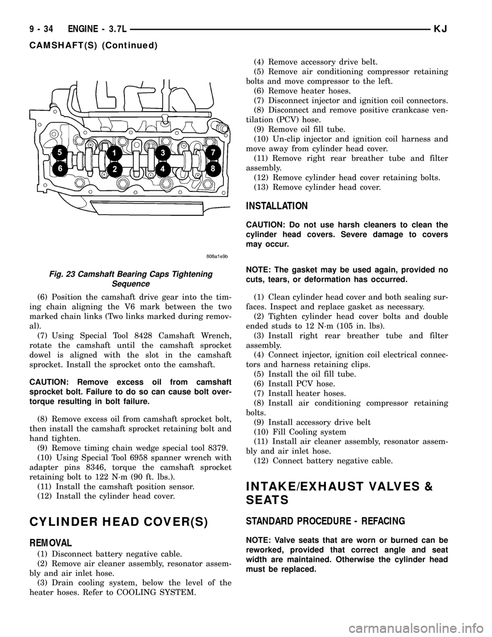
(4) Working in 1/2 turn increments, tighten the
bearing cap retaining bolts starting with the middle
cap working outward (Fig. 23).
(5) Torque the camshaft bearing cap retaining
bolts to 11 N´m (100 in. lbs.).
KJENGINE - 3.7L 9 - 33
CYLINDER HEAD - RIGHT (Continued)
Page 1249 of 1803
(6) Position the camshaft drive gear into the tim-
ing chain aligning the V6 mark between the two
marked chain links (Two links marked during remov-
al).
(7) Using Special Tool 8428 Camshaft Wrench,
rotate the camshaft until the camshaft sprocket
dowel is aligned with the slot in the camshaft
sprocket. Install the sprocket onto the camshaft.
CAUTION: Remove excess oil from camshaft
sprocket bolt. Failure to do so can cause bolt over-
torque resulting in bolt failure.
(8) Remove excess oil from camshaft sprocket bolt,
then install the camshaft sprocket retaining bolt and
hand tighten.
(9) Remove timing chain wedge special tool 8379.
(10) Using Special Tool 6958 spanner wrench with
adapter pins 8346, torque the camshaft sprocket
retaining bolt to 122 N´m (90 ft. lbs.).
(11) Install the camshaft position sensor.
(12) Install the cylinder head cover.
CYLINDER HEAD COVER(S)
REMOVAL
(1) Disconnect battery negative cable.
(2) Remove air cleaner assembly, resonator assem-
bly and air inlet hose.
(3) Drain cooling system, below the level of the
heater hoses. Refer to COOLING SYSTEM.(4) Remove accessory drive belt.
(5) Remove air conditioning compressor retaining
bolts and move compressor to the left.
(6) Remove heater hoses.
(7) Disconnect injector and ignition coil connectors.
(8) Disconnect and remove positive crankcase ven-
tilation (PCV) hose.
(9) Remove oil fill tube.
(10) Un-clip injector and ignition coil harness and
move away from cylinder head cover.
(11) Remove right rear breather tube and filter
assembly.
(12) Remove cylinder head cover retaining bolts.
(13) Remove cylinder head cover.
INSTALLATION
CAUTION: Do not use harsh cleaners to clean the
cylinder head covers. Severe damage to covers
may occur.
NOTE: The gasket may be used again, provided no
cuts, tears, or deformation has occurred.
(1) Clean cylinder head cover and both sealing sur-
faces. Inspect and replace gasket as necessary.
(2) Tighten cylinder head cover bolts and double
ended studs to 12 N´m (105 in. lbs).
(3) Install right rear breather tube and filter
assembly.
(4) Connect injector, ignition coil electrical connec-
tors and harness retaining clips.
(5) Install the oil fill tube.
(6) Install PCV hose.
(7) Install heater hoses.
(8) Install air conditioning compressor retaining
bolts.
(9) Install accessory drive belt
(10) Fill Cooling system
(11) Install air cleaner assembly, resonator assem-
bly and air inlet hose.
(12) Connect battery negative cable.
INTAKE/EXHAUST VALVES &
SEATS
STANDARD PROCEDURE - REFACING
NOTE: Valve seats that are worn or burned can be
reworked, provided that correct angle and seat
width are maintained. Otherwise the cylinder head
must be replaced.
Fig. 23 Camshaft Bearing Caps Tightening
Sequence
9 - 34 ENGINE - 3.7LKJ
CAMSHAFT(S) (Continued)
Page 1257 of 1803
Bearing
MarkSIZE USED WITH
JOURNAL SIZE
.025 US.025 mm 50.983-50.967 mm
(.001 in.) (2.0073-2.0066 in.)
Std.STANDARD 50.992-51.008 mm
(2.0076-2.0082 in.)
.250 US.250 mm 50.758-50.742 mm
(.010 in.) (1.9984-1.9978 in.)
(9) Repeat the Plastigage measurement to verify
your bearing selection prior to final assembly.
(10) Once you have selected the proper insert,
install the insert and cap. Tighten the connecting rod
bolts to 27 N´m (20 ft. lbs.) plus a 90É turn.
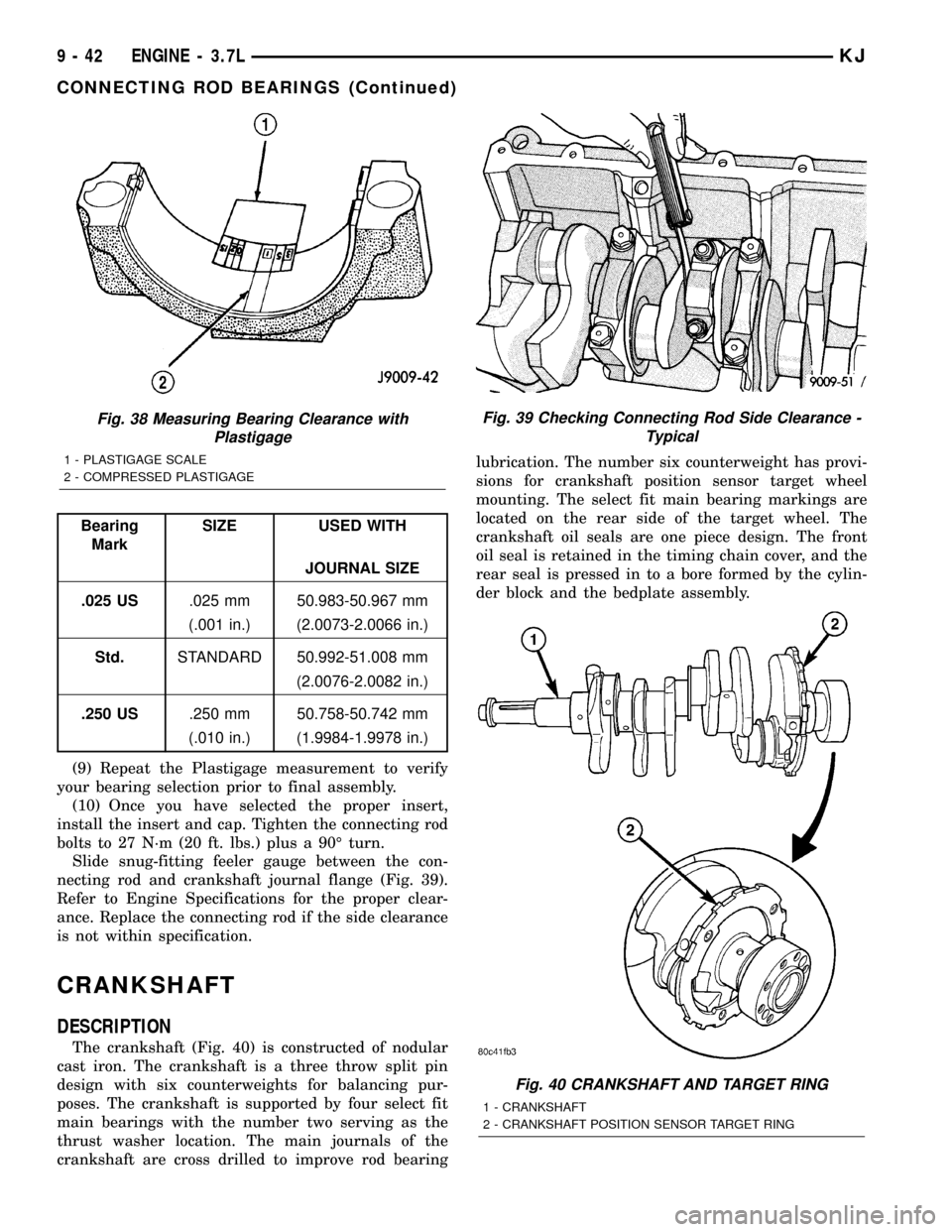
Slide snug-fitting feeler gauge between the con-
necting rod and crankshaft journal flange (Fig. 39).
Refer to Engine Specifications for the proper clear-
ance. Replace the connecting rod if the side clearance
is not within specification.
CRANKSHAFT
DESCRIPTION
The crankshaft (Fig. 40) is constructed of nodular
cast iron. The crankshaft is a three throw split pin
design with six counterweights for balancing pur-
poses. The crankshaft is supported by four select fit
main bearings with the number two serving as the
thrust washer location. The main journals of the
crankshaft are cross drilled to improve rod bearinglubrication. The number six counterweight has provi-
sions for crankshaft position sensor target wheel
mounting. The select fit main bearing markings are
located on the rear side of the target wheel. The
crankshaft oil seals are one piece design. The front
oil seal is retained in the timing chain cover, and the
rear seal is pressed in to a bore formed by the cylin-
der block and the bedplate assembly.
Fig. 38 Measuring Bearing Clearance with
Plastigage
1 - PLASTIGAGE SCALE
2 - COMPRESSED PLASTIGAGE
Fig. 39 Checking Connecting Rod Side Clearance -
Typical
Fig. 40 CRANKSHAFT AND TARGET RING
1 - CRANKSHAFT
2 - CRANKSHAFT POSITION SENSOR TARGET RING
9 - 42 ENGINE - 3.7LKJ
CONNECTING ROD BEARINGS (Continued)
Page 1262 of 1803
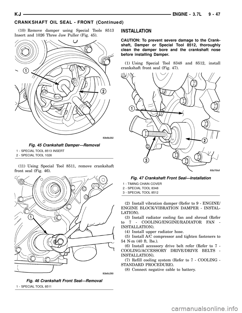
(10) Remove damper using Special Tools 8513
Insert and 1026 Three Jaw Puller (Fig. 45).
(11) Using Special Tool 8511, remove crankshaft
front seal (Fig. 46).INSTALLATION
CAUTION: To prevent severe damage to the Crank-
shaft, Damper or Special Tool 8512, thoroughly
clean the damper bore and the crankshaft nose
before installing Damper.
(1) Using Special Tool 8348 and 8512, install
crankshaft front seal (Fig. 47).
(2) Install vibration damper (Refer to 9 - ENGINE/
ENGINE BLOCK/VIBRATION DAMPER - INSTAL-
LATION).
(3) Install radiator cooling fan and shroud (Refer
to 7 - COOLING/ENGINE/RADIATOR FAN -
INSTALLATION).
(4) Install upper radiator hose.
(5) Install A/C compressor and tighten fasteners to
54 N´m (40 ft. lbs.).
(6) Install accessory drive belt refer (Refer to 7 -
COOLING/ACCESSORY DRIVE/DRIVE BELTS -
INSTALLATION).
(7) Refill cooling system (Refer to 7 - COOLING -
STANDARD PROCEDURE).
(8) Connect negative cable to battery.
Fig. 45 Crankshaft DamperÐRemoval
1 - SPECIAL TOOL 8513 INSERT
2 - SPECIAL TOOL 1026
Fig. 46 Crankshaft Front SealÐRemoval
1 - SPECIAL TOOL 8511
Fig. 47 Crankshaft Front SealÐInstallation
1 - TIMING CHAIN COVER
2 - SPECIAL TOOL 8348
3 - SPECIAL TOOL 8512
KJENGINE - 3.7L 9 - 47
CRANKSHAFT OIL SEAL - FRONT (Continued)
Page 1265 of 1803
90É turn. DO NOT rotate crankshaft. Plastigage will
smear, resulting in inaccurate indication.
(6) Remove the bearing cap and determine amount
of bearing-to-journal clearance by measuring the
width of compressed Plastigage. Refer to Engine
Specifications for the proper clearance.Plastigage
should indicate the same clearance across the
entire width of the insert. If the clearance var-
ies, it may be caused by either a tapered jour-
nal, bent connecting rod or foreign material
trapped between the insert and cap or rod.
(7) If the correct clearance is indicated, replace-
ment of the bearing inserts is not necessary. Remove
the Plastigage from crankshaft journal and bearing
insert. Proceed with installation.
(8) If bearing-to-journal clearance exceeds the
specification, determin which services bearing set to
use the bearing sizes are as follows:
Bearing
MarkSIZE USED WITH
JOURNAL SIZE
.025 US.025 mm 57.871-57.879 mm
(.001 in.) (2.2783-2.2786 in.)
Std.STANDARD 57.896-57.904 mm
(2.2793-2.2810 in.)
.250 US.250 mm 57.646-57.654 mm
(.010 in.) (2.2695-2.2698 in.)
(9) Repeat the Plastigage measurement to verify
your bearing selection prior to final assembly.
(10) Once you have selected the proper insert,
install the insert and cap. Tighten the connecting rod
bolts to 27 N´m (20 ft. lbs.) plus a 90É turn.
Slide snug-fitting feeler gauge between the con-
necting rod and crankshaft journal flange. Refer to
Engine Specifications for the proper clearance.
Replace the connecting rod if the side clearance is
not within specification.
STANDARD PROCEDURE - PISTON FITTING
(1) To correctly select the proper size piston, a cyl-
inder bore gauge, capable of reading in 0.003 mm (
.0001 in.) INCREMENTS is required. If a bore gauge
is not available, do not use an inside micrometer.
(2) Measure the inside diameter of the cylinder
bore at a point 38.0 mm (1.5 inches) below top of
bore. Start perpendicular (across or at 90 degrees) to
the axis of the crankshaft at point A and then take
an additional bore reading 90 degrees to that at point
B (Fig. 54).
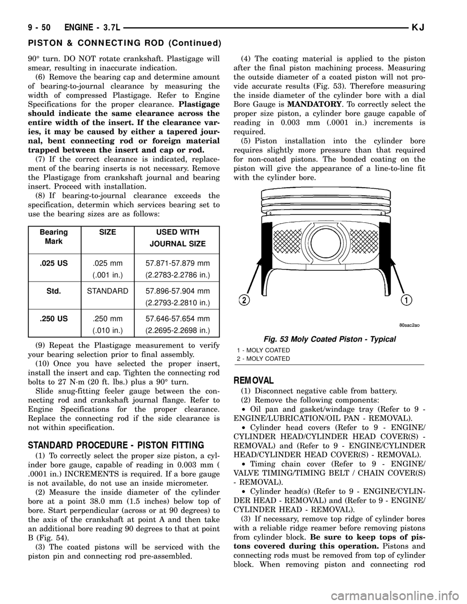
(3) The coated pistons will be serviced with the
piston pin and connecting rod pre-assembled.(4) The coating material is applied to the piston
after the final piston machining process. Measuring
the outside diameter of a coated piston will not pro-
vide accurate results (Fig. 53). Therefore measuring
the inside diameter of the cylinder bore with a dial
Bore Gauge isMANDATORY. To correctly select the
proper size piston, a cylinder bore gauge capable of
reading in 0.003 mm (.0001 in.) increments is
required.
(5) Piston installation into the cylinder bore
requires slightly more pressure than that required
for non-coated pistons. The bonded coating on the
piston will give the appearance of a line-to-line fit
with the cylinder bore.
REMOVAL
(1) Disconnect negative cable from battery.
(2) Remove the following components:
²Oil pan and gasket/windage tray (Refer to 9 -
ENGINE/LUBRICATION/OIL PAN - REMOVAL).
²Cylinder head covers (Refer to 9 - ENGINE/
CYLINDER HEAD/CYLINDER HEAD COVER(S) -
REMOVAL) and (Refer to 9 - ENGINE/CYLINDER
HEAD/CYLINDER HEAD COVER(S) - REMOVAL).
²Timing chain cover (Refer to 9 - ENGINE/
VALVE TIMING/TIMING BELT / CHAIN COVER(S)
- REMOVAL).
²Cylinder head(s) (Refer to 9 - ENGINE/CYLIN-
DER HEAD - REMOVAL) and (Refer to 9 - ENGINE/
CYLINDER HEAD - REMOVAL).
(3) If necessary, remove top ridge of cylinder bores
with a reliable ridge reamer before removing pistons
from cylinder block.Be sure to keep tops of pis-
tons covered during this operation.Pistons and
connecting rods must be removed from top of cylinder
block. When removing piston and connecting rod
Fig. 53 Moly Coated Piston - Typical
1 - MOLY COATED
2 - MOLY COATED
9 - 50 ENGINE - 3.7LKJ
PISTON & CONNECTING ROD (Continued)
Page 1267 of 1803
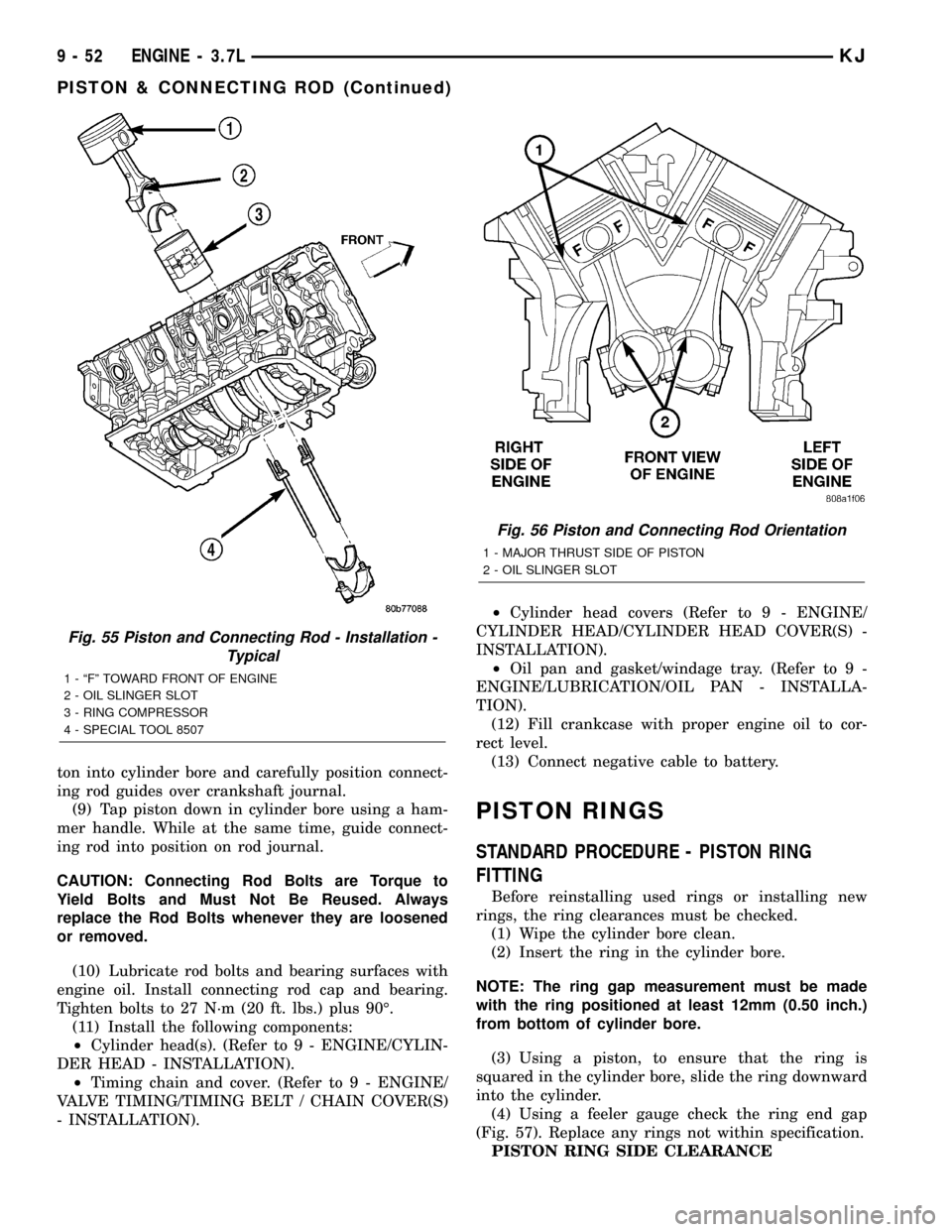
ton into cylinder bore and carefully position connect-
ing rod guides over crankshaft journal.
(9) Tap piston down in cylinder bore using a ham-
mer handle. While at the same time, guide connect-
ing rod into position on rod journal.
CAUTION: Connecting Rod Bolts are Torque to
Yield Bolts and Must Not Be Reused. Always
replace the Rod Bolts whenever they are loosened
or removed.
(10) Lubricate rod bolts and bearing surfaces with
engine oil. Install connecting rod cap and bearing.
Tighten bolts to 27 N´m (20 ft. lbs.) plus 90É.
(11) Install the following components:
²Cylinder head(s). (Refer to 9 - ENGINE/CYLIN-
DER HEAD - INSTALLATION).
²Timing chain and cover. (Refer to 9 - ENGINE/
VALVE TIMING/TIMING BELT / CHAIN COVER(S)
- INSTALLATION).²Cylinder head covers (Refer to 9 - ENGINE/
CYLINDER HEAD/CYLINDER HEAD COVER(S) -
INSTALLATION).
²Oil pan and gasket/windage tray. (Refer to 9 -
ENGINE/LUBRICATION/OIL PAN - INSTALLA-
TION).
(12) Fill crankcase with proper engine oil to cor-
rect level.
(13) Connect negative cable to battery.
PISTON RINGS
STANDARD PROCEDURE - PISTON RING
FITTING
Before reinstalling used rings or installing new
rings, the ring clearances must be checked.
(1) Wipe the cylinder bore clean.
(2) Insert the ring in the cylinder bore.
NOTE: The ring gap measurement must be made
with the ring positioned at least 12mm (0.50 inch.)
from bottom of cylinder bore.
(3) Using a piston, to ensure that the ring is
squared in the cylinder bore, slide the ring downward
into the cylinder.
(4) Using a feeler gauge check the ring end gap
(Fig. 57). Replace any rings not within specification.
PISTON RING SIDE CLEARANCE
Fig. 55 Piston and Connecting Rod - Installation -
Typical
1 - ªFº TOWARD FRONT OF ENGINE
2 - OIL SLINGER SLOT
3 - RING COMPRESSOR
4 - SPECIAL TOOL 8507
Fig. 56 Piston and Connecting Rod Orientation
1 - MAJOR THRUST SIDE OF PISTON
2 - OIL SLINGER SLOT
9 - 52 ENGINE - 3.7LKJ
PISTON & CONNECTING ROD (Continued)
Page 1273 of 1803
OPERATION
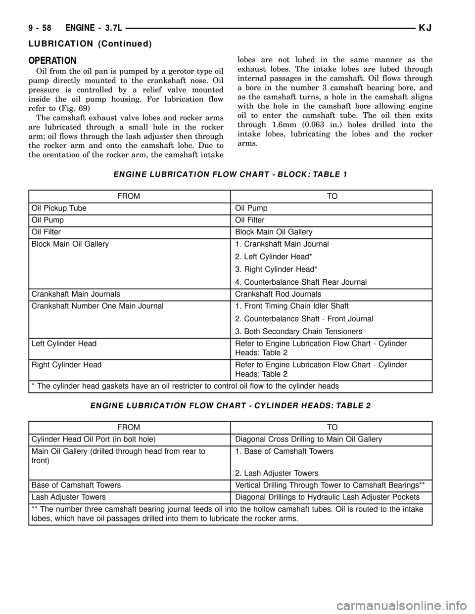
Oil from the oil pan is pumped by a gerotor type oil
pump directly mounted to the crankshaft nose. Oil
pressure is controlled by a relief valve mounted
inside the oil pump housing. For lubrication flow
refer to (Fig. 69)
The camshaft exhaust valve lobes and rocker arms
are lubricated through a small hole in the rocker
arm; oil flows through the lash adjuster then through
the rocker arm and onto the camshaft lobe. Due to
the orentation of the rocker arm, the camshaft intakelobes are not lubed in the same manner as the
exhaust lobes. The intake lobes are lubed through
internal passages in the camshaft. Oil flows through
a bore in the number 3 camshaft bearing bore, and
as the camshaft turns, a hole in the camshaft aligns
with the hole in the camshaft bore allowing engine
oil to enter the camshaft tube. The oil then exits
through 1.6mm (0.063 in.) holes drilled into the
intake lobes, lubricating the lobes and the rocker
arms.
ENGINE LUBRICATION FLOW CHART - BLOCK: TABLE 1
FROM TO
Oil Pickup Tube Oil Pump
Oil Pump Oil Filter
Oil Filter Block Main Oil Gallery
Block Main Oil Gallery 1. Crankshaft Main Journal
2. Left Cylinder Head*
3. Right Cylinder Head*
4. Counterbalance Shaft Rear Journal
Crankshaft Main Journals Crankshaft Rod Journals
Crankshaft Number One Main Journal 1. Front Timing Chain Idler Shaft
2. Counterbalance Shaft - Front Journal
3. Both Secondary Chain Tensioners
Left Cylinder Head Refer to Engine Lubrication Flow Chart - Cylinder
Heads: Table 2
Right Cylinder Head Refer to Engine Lubrication Flow Chart - Cylinder
Heads: Table 2
* The cylinder head gaskets have an oil restricter to control oil flow to the cylinder heads
ENGINE LUBRICATION FLOW CHART - CYLINDER HEADS: TABLE 2
FROM TO
Cylinder Head Oil Port (in bolt hole) Diagonal Cross Drilling to Main Oil Gallery
Main Oil Gallery (drilled through head from rear to
front)1. Base of Camshaft Towers
2. Lash Adjuster Towers
Base of Camshaft Towers Vertical Drilling Through Tower to Camshaft Bearings**
Lash Adjuster Towers Diagonal Drillings to Hydraulic Lash Adjuster Pockets
** The number three camshaft bearing journal feeds oil into the hollow camshaft tubes. Oil is routed to the intake
lobes, which have oil passages drilled into them to lubricate the rocker arms.
9 - 58 ENGINE - 3.7LKJ
LUBRICATION (Continued)