2002 JEEP LIBERTY Timing
[x] Cancel search: TimingPage 401 of 1803

subjected to a high torque load, deposits partially liq-
uefy and bridge the gap between electrodes (Fig. 23).
This short circuits the electrodes. Spark plugs with
electrode gap bridging can be cleaned using standard
procedures.
SCAVENGER DEPOSITS
Fuel scavenger deposits may be either white or yel-
low (Fig. 24). They may appear to be harmful, but
this is a normal condition caused by chemical addi-
tives in certain fuels. These additives are designed to
change the chemical nature of deposits and decrease
spark plug misfire tendencies. Notice that accumula-
tion on the ground electrode and shell area may be
heavy, but the deposits are easily removed. Spark
plugs with scavenger deposits can be considered nor-
mal in condition and can be cleaned using standard
procedures.
CHIPPED ELECTRODE INSULATOR
A chipped electrode insulator usually results from
bending the center electrode while adjusting the
spark plug electrode gap. Under certain conditions,
severe detonation can also separate the insulator
from the center electrode (Fig. 25). Spark plugs with
this condition must be replaced.
PREIGNITION DAMAGE
Preignition damage is usually caused by excessive
combustion chamber temperature. The center elec-
trode dissolves first and the ground electrode dis-
solves somewhat latter (Fig. 26). Insulators appear
relatively deposit free. Determine if the spark plug
has the correct heat range rating for the engine.
Determine if ignition timing is over advanced or if
other operating conditions are causing engine over-heating. (The heat range rating refers to the operat-
ing temperature of a particular type spark plug.
Spark plugs are designed to operate within specific
temperature ranges. This depends upon the thick-
ness and length of the center electrodes porcelain
insulator.)
SPARK PLUG OVERHEATING
Overheating is indicated by a white or gray center
electrode insulator that also appears blistered (Fig.
27). The increase in electrode gap will be consider-
ably in excess of 0.001 inch per 2000 miles of opera-
tion. This suggests that a plug with a cooler heat
range rating should be used. Over advanced ignition
timing, detonation and cooling system malfunctions
can also cause spark plug overheating.
Fig. 23 Electrode Gap Bridging
1 - GROUND ELECTRODE
2 - DEPOSITS
3 - CENTER ELECTRODE
Fig. 24 Scavenger Deposits
1 - GROUND ELECTRODE COVERED WITH WHITE OR
YELLOW DEPOSITS
2 - CENTER ELECTRODE
Fig. 25 Chipped Electrode Insulator
1 - GROUND ELECTRODE
2 - CENTER ELECTRODE
3 - CHIPPED INSULATOR
8I - 14 IGNITION CONTROLKJ
SPARK PLUG (Continued)
Page 706 of 1803

Following are paragraphs that briefly describe the
operation of each of the front wiper and washer sys-
tem operating modes.
CONTINUOUS WIPE MODE When the Low posi-
tion of the control knob on the right (wiper) control
stalk of the multi-function switch is selected, the
Body Control Module (BCM) energizes the wiper
on/off relay. This directs battery current through the
normally open contacts of the energized wiper on/off
relay and the normally closed contacts of the de-en-
ergized wiper high/low relay to the low speed brush
of the front wiper motor, causing the front wipers to
cycle at low speed. When the High position of the
control knob is selected, the BCM energizes both the
wiper on/off relay and the wiper high/low relay. This
directs battery current through the normally open
contacts of the energized wiper on/off relay and the
normally open contacts of the energized wiper high/
low relay to the high speed brush of the front wiper
motor, causing the front wipers to cycle at high
speed.
When the Off position of the control knob is
selected, the BCM de-energizes both the wiper on/off
and wiper high low relays, then one of two events
will occur. The event that occurs depends upon the
position of the wiper blades on the windshield at the
moment that the control knob Off position is selected.
If the wiper blades are in the down position on the
windshield when the Off position is selected, the
park switch that is integral to the front wiper motor
is closed to ground and the wiper motor ceases to
operate. If the wiper blades are not in the down posi-
tion on the windshield at the moment the Off posi-
tion is selected, the park switch is closed to battery
current from the fused ignition switch output (run-
acc) circuit of the front wiper motor. The park switch
directs this battery current to the low speed brush of
the wiper motor through the wiper park switch sense
circuit and the normally closed contacts of the de-en-
ergized wiper on/off and wiper high/low relays. This
causes the wiper motor to continue running at low
speed until the wiper blades are in the down position
on the windshield and the park switch is again
closed to ground.
INTERMITTENT WIPE MODE When the control
knob on the right (wiper) control stalk of the multi-
function switch is moved to one of the Delay interval
positions, the BCM electronic intermittent wipe logic
circuit responds by calculating the correct length of
time between wiper sweeps based upon the selected
delay interval input. The BCM monitors the chang-
ing state of the wiper motor park switch through a
hard wired front wiper park switch sense circuit
input. This input allows the BCM to determine the
proper intervals at which to energize and de-energize
the wiper on/off relay to operate the front wipermotor intermittently for one low speed cycle at a
time. The BCM logic is also programmed to provide
an immediate wipe cycle and begin a new delay
interval timing cycle each time a shorter delay inter-
val is selected, and to add the remaining delay tim-
ing interval to the new delay interval timing before
the next wipe cycle occurs each time a longer delay
interval is selected.
MIST WIPE MODE When the right (wiper) control
stalk of the multi-function switch is moved to the
momentary Mist position, the BCM energizes the
wiper on/off relay for as long as the Mist switch is
held closed, then de-energizes the relay when the
state of the Mist switch input changes to open. The
BCM can operate the front wiper motor in this mode
for only one low speed cycle at a time, or for an
indefinite number of sequential low speed cycles,
depending upon how long the Mist switch is held
closed.
WASH MODE When the right (wiper) control stalk
of the multi-function switch is moved to the momen-
tary front Wash position while the control knob is in
the Low or High positions, the circuitry within the
switch directs battery current and ground to the
washer pump/motor unit. This will cause the washer
pump/motor unit to be energized for as long as the
front Wash switch is held closed, and to de-energize
when the front Wash switch is released. When the
right (wiper) control stalk of the multi-function
switch is moved to the momentary front Wash posi-
tion while the control knob is in one of the Delay
interval positions, the front washer pump/motor oper-
ation is the same. However, the BCM energizes the
wiper on/off relay to override the selected delay inter-
val and operate the front wiper motor in a continu-
ous low speed mode for as long as the front Wash
switch is held closed, then de-energizes the relay and
reverts to the selected delay mode interval several
wipe cycles after the front Wash switch is released.
The BCM detects the front Wash switch state
through a hard wired washer pump driver circuit
input from the multi-function switch.
WIPE-AFTER-WASH MODE When the right
(wiper) control stalk of the multi-function switch is
moved to the momentary front Wash position while
the control knob is in the Off position, the BCM
detects that switch state through a hard wired
washer pump driver circuit input from the multi-
function switch. The BCM responds to this input by
energizing the wiper on/off relay for as long as the
Wash switch is held closed, then de-energizes the
relay several wipe cycles after the front Wash switch
is released. The BCM monitors the changing state of
the wiper motor park switch through a hard wired
front wiper park switch sense circuit input. This
input allows the BCM to count the number of wipe
KJFRONT WIPERS/WASHERS 8R - 5
FRONT WIPERS/WASHERS (Continued)
Page 1217 of 1803

ENGINE BLOCK
DESCRIPTION.........................39
STANDARD PROCEDURE - CYLINDER BORE
HONING............................39
CLEANING............................39
INSPECTION..........................40
CONNECTING ROD BEARINGS
STANDARD PROCEDURE - CONNECTING
ROD BEARING - FITTING...............40
CRANKSHAFT
DESCRIPTION.........................42
REMOVAL.............................43
INSPECTION..........................43
INSTALLATION.........................43
CRANKSHAFT MAIN BEARINGS
STANDARD PROCEDURE
MAIN BEARING - FITTING...............45
CRANKSHAFT OIL SEAL - FRONT
REMOVAL.............................46
INSTALLATION.........................47
CRANKSHAFT OIL SEAL - REAR
REMOVAL.............................48
INSTALLATION.........................48
FLEX PLATE
REMOVAL.............................49
INSTALLATION.........................49
PISTON & CONNECTING ROD
DESCRIPTION.........................49
STANDARD PROCEDURE
CONNECTING ROD BEARING - FITTING . . . 49
STANDARD PROCEDURE - PISTON
FITTING.............................50
REMOVAL.............................50
CLEANING............................51
INSPECTION..........................51
INSTALLATION.........................51
PISTON RINGS
STANDARD PROCEDURE - PISTON RING
FITTING.............................52
VIBRATION DAMPER
REMOVAL.............................54
INSTALLATION.........................55
STRUCTURAL COVER
DESCRIPTION.........................55
OPERATION...........................55
REMOVAL.............................55
INSTALLATION.........................55
FRONT MOUNT
REMOVAL.............................56
INSTALLATION.........................57
REAR MOUNT
REMOVAL.............................57
INSTALLATION.........................57
LUBRICATION
DESCRIPTION.........................57
OPERATION...........................58DIAGNOSIS AND TESTING
DIAGNOSIS AND TESTING - ENGINE OIL
LEAK...............................60
DIAGNOSIS AND TESTING - ENGINE OIL
PRESSURE..........................60
DIAGNOSIS AND TESTING - REAR SEAL
AREA LEAKS.........................61
OIL
STANDARD PROCEDURE - ENGINE OIL.....61
OIL FILTER
REMOVAL.............................63
INSTALLATION.........................63
OIL PAN
DESCRIPTION.........................63
REMOVAL.............................63
CLEANING............................63
INSPECTION..........................63
INSTALLATION.........................64
OIL PRESSURE SENSOR/SWITCH
DESCRIPTION.........................65
OPERATION...........................65
REMOVAL.............................65
INSTALLATION.........................65
OIL PUMP
REMOVAL.............................65
DISASSEMBLY.........................65
INSPECTION..........................66
ASSEMBLY............................67
INSTALLATION.........................67
INTAKE MANIFOLD
DESCRIPTION.........................68
DIAGNOSIS AND TESTING - INTAKE
MANIFOLD LEAKS.....................68
REMOVAL.............................68
INSTALLATION.........................69
EXHAUST MANIFOLD
DESCRIPTION.........................69
REMOVAL.............................69
INSTALLATION.........................70
VALVE TIMING
DESCRIPTION.........................71
OPERATION...........................71
STANDARD PROCEDURE
MEASURING TIMING CHAIN WEAR.......71
SERVICE PROCEDURES...............72
BALANCE SHAFT
REMOVAL.............................74
INSTALLATION.........................74
TIMING BELT / CHAIN COVER(S)
REMOVAL.............................74
INSTALLATION.........................76
IDLER SHAFT
REMOVAL.............................77
INSTALLATION.........................77
TIMING BELT/CHAIN AND SPROCKET(S
REMOVAL.............................77
INSPECTION..........................79
INSTALLATION.........................80
9 - 2 ENGINE - 3.7LKJ
Page 1219 of 1803
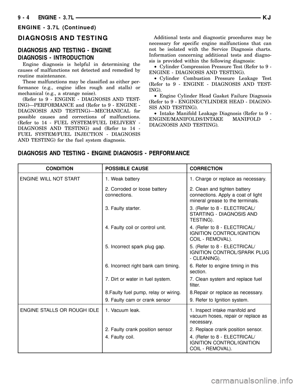
DIAGNOSIS AND TESTING
DIAGNOSIS AND TESTING - ENGINE
DIAGNOSIS - INTRODUCTION
Engine diagnosis is helpful in determining the
causes of malfunctions not detected and remedied by
routine maintenance.
These malfunctions may be classified as either per-
formance (e.g., engine idles rough and stalls) or
mechanical (e.g., a strange noise).
(Refer to 9 - ENGINE - DIAGNOSIS AND TEST-
ING)ÐPERFORMANCE and (Refer to 9 - ENGINE -
DIAGNOSIS AND TESTING)ÐMECHANICAL for
possible causes and corrections of malfunctions.
(Refer to 14 - FUEL SYSTEM/FUEL DELIVERY -
DIAGNOSIS AND TESTING) and (Refer to 14 -
FUEL SYSTEM/FUEL INJECTION - DIAGNOSIS
AND TESTING) for the fuel system diagnosis.Additional tests and diagnostic procedures may be
necessary for specific engine malfunctions that can
not be isolated with the Service Diagnosis charts.
Information concerning additional tests and diagno-
sis is provided within the following diagnosis:
²Cylinder Compression Pressure Test (Refer to 9 -
ENGINE - DIAGNOSIS AND TESTING).
²Cylinder Combustion Pressure Leakage Test
(Refer to 9 - ENGINE - DIAGNOSIS AND TEST-
ING).
²Engine Cylinder Head Gasket Failure Diagnosis
(Refer to 9 - ENGINE/CYLINDER HEAD - DIAGNO-
SIS AND TESTING).
²Intake Manifold Leakage Diagnosis (Refer to 9 -
ENGINE/MANIFOLDS/INTAKE MANIFOLD -
DIAGNOSIS AND TESTING).
DIAGNOSIS AND TESTING - ENGINE DIAGNOSIS - PERFORMANCE
CONDITION POSSIBLE CAUSE CORRECTION
ENGINE WILL NOT START 1. Weak battery 1. Charge or replace as necessary.
2. Corroded or loose battery
connections.2. Clean and tighten battery
connections. Apply a coat of light
mineral grease to the terminals.
3. Faulty starter. 3. (Refer to 8 - ELECTRICAL/
STARTING - DIAGNOSIS AND
TESTING).
4. Faulty coil or control unit. 4. (Refer to 8 - ELECTRICAL/
IGNITION CONTROL/IGNITION
COIL - REMOVAL).
5. Incorrect spark plug gap. 5. (Refer to 8 - ELECTRICAL/
IGNITION CONTROL/SPARK PLUG
- CLEANING).
6. Incorrect right bank cam timing. 6. Refer to engine timing in this
section.
7. Dirt or water in fuel system. 7. Clean system and replace fuel
filter.
8.Faulty fuel pump, relay or wiring. 8.Repair or replace as necessary.
9. Faulty cam or crank sensor 9. Refer to Ignition system.
ENGINE STALLS OR ROUGH IDLE 1. Vacuum leak. 1. Inspect intake manifold and
vacuum hoses, repair or replace as
necessary.
2. Faulty crank position sensor 2. Replace crank position sensor.
4. Faulty coil. 4. (Refer to 8 - ELECTRICAL/
IGNITION CONTROL/IGNITION
COIL - REMOVAL).
9 - 4 ENGINE - 3.7LKJ
ENGINE - 3.7L (Continued)
Page 1220 of 1803
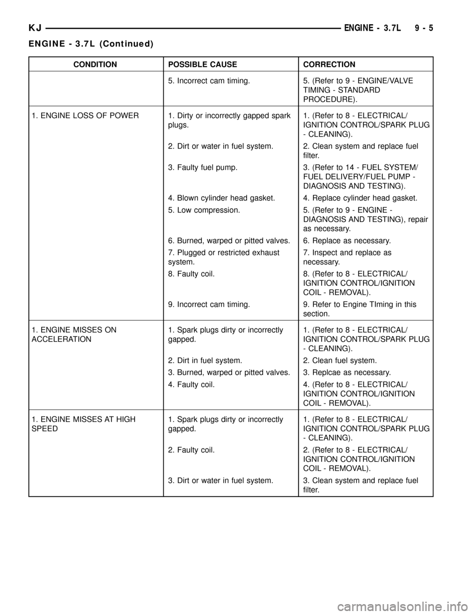
CONDITION POSSIBLE CAUSE CORRECTION
5. Incorrect cam timing. 5. (Refer to 9 - ENGINE/VALVE
TIMING - STANDARD
PROCEDURE).
1. ENGINE LOSS OF POWER 1. Dirty or incorrectly gapped spark
plugs.1. (Refer to 8 - ELECTRICAL/
IGNITION CONTROL/SPARK PLUG
- CLEANING).
2. Dirt or water in fuel system. 2. Clean system and replace fuel
filter.
3. Faulty fuel pump. 3. (Refer to 14 - FUEL SYSTEM/
FUEL DELIVERY/FUEL PUMP -
DIAGNOSIS AND TESTING).
4. Blown cylinder head gasket. 4. Replace cylinder head gasket.
5. Low compression. 5. (Refer to 9 - ENGINE -
DIAGNOSIS AND TESTING), repair
as necessary.
6. Burned, warped or pitted valves. 6. Replace as necessary.
7. Plugged or restricted exhaust
system.7. Inspect and replace as
necessary.
8. Faulty coil. 8. (Refer to 8 - ELECTRICAL/
IGNITION CONTROL/IGNITION
COIL - REMOVAL).
9. Incorrect cam timing. 9. Refer to Engine TIming in this
section.
1. ENGINE MISSES ON
ACCELERATION1. Spark plugs dirty or incorrectly
gapped.1. (Refer to 8 - ELECTRICAL/
IGNITION CONTROL/SPARK PLUG
- CLEANING).
2. Dirt in fuel system. 2. Clean fuel system.
3. Burned, warped or pitted valves. 3. Replcae as necessary.
4. Faulty coil. 4. (Refer to 8 - ELECTRICAL/
IGNITION CONTROL/IGNITION
COIL - REMOVAL).
1. ENGINE MISSES AT HIGH
SPEED1. Spark plugs dirty or incorrectly
gapped.1. (Refer to 8 - ELECTRICAL/
IGNITION CONTROL/SPARK PLUG
- CLEANING).
2. Faulty coil. 2. (Refer to 8 - ELECTRICAL/
IGNITION CONTROL/IGNITION
COIL - REMOVAL).
3. Dirt or water in fuel system. 3. Clean system and replace fuel
filter.
KJENGINE - 3.7L 9 - 5
ENGINE - 3.7L (Continued)
Page 1221 of 1803
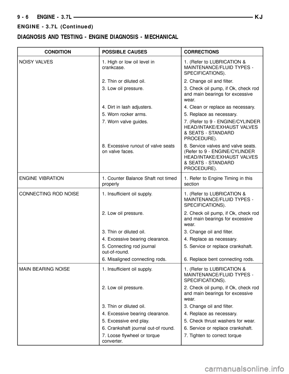
DIAGNOSIS AND TESTING - ENGINE DIAGNOSIS - MECHANICAL
CONDITION POSSIBLE CAUSES CORRECTIONS
NOISY VALVES 1. High or low oil level in
crankcase.1. (Refer to LUBRICATION &
MAINTENANCE/FLUID TYPES -
SPECIFICATIONS).
2. Thin or diluted oil. 2. Change oil and filter.
3. Low oil pressure. 3. Check oil pump, if Ok, check rod
and main bearings for excessive
wear.
4. Dirt in lash adjusters. 4. Clean or replace as necessary.
5. Worn rocker arms. 5. Replace as necessary.
7. Worn valve guides. 7. (Refer to 9 - ENGINE/CYLINDER
HEAD/INTAKE/EXHAUST VALVES
& SEATS - STANDARD
PROCEDURE).
8. Excessive runout of valve seats
on valve faces.8. Service valves and valve seats.
(Refer to 9 - ENGINE/CYLINDER
HEAD/INTAKE/EXHAUST VALVES
& SEATS - STANDARD
PROCEDURE).
ENGINE VIBRATION 1. Counter Balance Shaft not timed
properly1. Refer to Engine Timing in this
section
CONNECTING ROD NOISE 1. Insufficient oil supply. 1. (Refer to LUBRICATION &
MAINTENANCE/FLUID TYPES -
SPECIFICATIONS).
2. Low oil pressure. 2. Check oil pump, if Ok, check rod
and main bearings for excessive
wear.
3. Thin or diluted oil. 3. Change oil and filter.
4. Excessive bearing clearance. 4. Replace as necessary.
5. Connecting rod journal
out-of-round.5. Service or replace crankshaft.
6. Misaligned connecting rods. 6. Replace bent connecting rods.
MAIN BEARING NOISE 1. Insufficient oil supply. 1. (Refer to LUBRICATION &
MAINTENANCE/FLUID TYPES -
SPECIFICATIONS).
2. Low oil pressure. 2. Check oil pump, if Ok, check rod
and main bearings for excessive
wear.
3. Thin or diluted oil. 3. Change oil and filter.
4. Excessive bearing clearance. 4. Replace as necessary.
5. Excessive end play. 5. Check thrust washers for wear.
6. Crankshaft journal out-of round. 6. Service or replace crankshaft.
7. Loose flywheel or torque
converter.7. Tighten to correct torque
9 - 6 ENGINE - 3.7LKJ
ENGINE - 3.7L (Continued)
Page 1222 of 1803
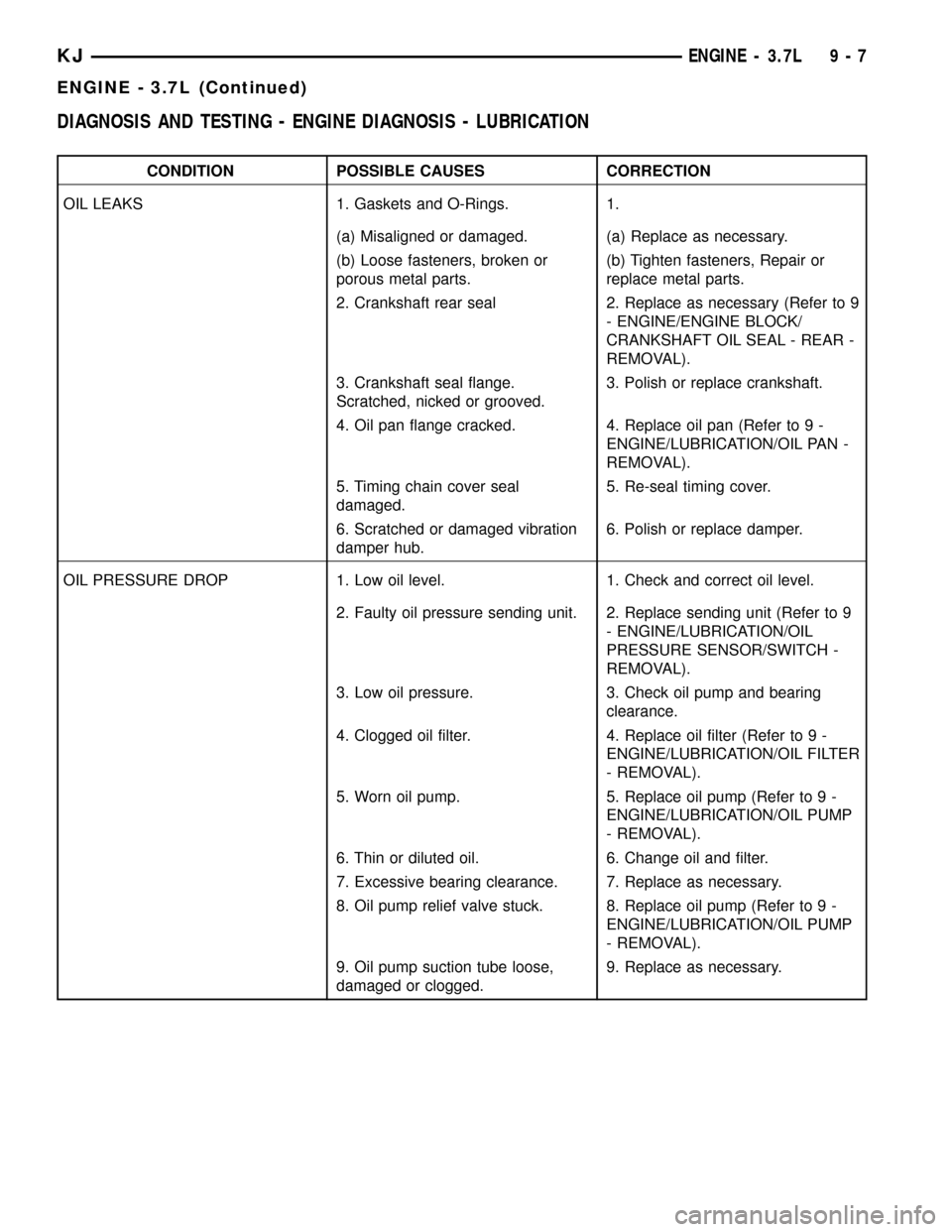
DIAGNOSIS AND TESTING - ENGINE DIAGNOSIS - LUBRICATION
CONDITION POSSIBLE CAUSES CORRECTION
OIL LEAKS 1. Gaskets and O-Rings. 1.
(a) Misaligned or damaged. (a) Replace as necessary.
(b) Loose fasteners, broken or
porous metal parts.(b) Tighten fasteners, Repair or
replace metal parts.
2. Crankshaft rear seal 2. Replace as necessary (Refer to 9
- ENGINE/ENGINE BLOCK/
CRANKSHAFT OIL SEAL - REAR -
REMOVAL).
3. Crankshaft seal flange.
Scratched, nicked or grooved.3. Polish or replace crankshaft.
4. Oil pan flange cracked. 4. Replace oil pan (Refer to 9 -
ENGINE/LUBRICATION/OIL PAN -
REMOVAL).
5. Timing chain cover seal
damaged.5. Re-seal timing cover.
6. Scratched or damaged vibration
damper hub.6. Polish or replace damper.
OIL PRESSURE DROP 1. Low oil level. 1. Check and correct oil level.
2. Faulty oil pressure sending unit. 2. Replace sending unit (Refer to 9
- ENGINE/LUBRICATION/OIL
PRESSURE SENSOR/SWITCH -
REMOVAL).
3. Low oil pressure. 3. Check oil pump and bearing
clearance.
4. Clogged oil filter. 4. Replace oil filter (Refer to 9 -
ENGINE/LUBRICATION/OIL FILTER
- REMOVAL).
5. Worn oil pump. 5. Replace oil pump (Refer to 9 -
ENGINE/LUBRICATION/OIL PUMP
- REMOVAL).
6. Thin or diluted oil. 6. Change oil and filter.
7. Excessive bearing clearance. 7. Replace as necessary.
8. Oil pump relief valve stuck. 8. Replace oil pump (Refer to 9 -
ENGINE/LUBRICATION/OIL PUMP
- REMOVAL).
9. Oil pump suction tube loose,
damaged or clogged.9. Replace as necessary.
KJENGINE - 3.7L 9 - 7
ENGINE - 3.7L (Continued)
Page 1227 of 1803
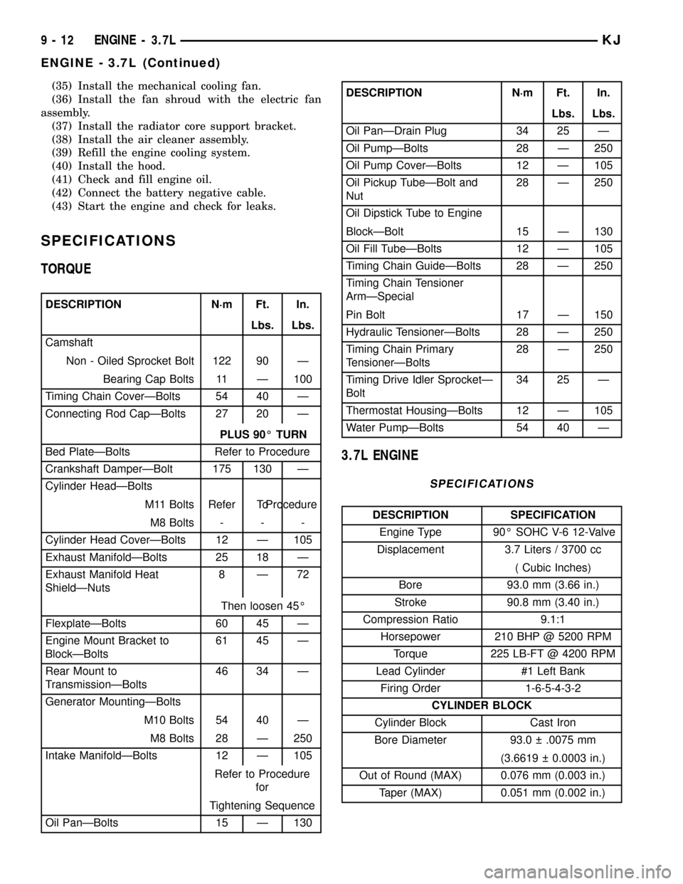
(35) Install the mechanical cooling fan.
(36) Install the fan shroud with the electric fan
assembly.
(37) Install the radiator core support bracket.
(38) Install the air cleaner assembly.
(39) Refill the engine cooling system.
(40) Install the hood.
(41) Check and fill engine oil.
(42) Connect the battery negative cable.
(43) Start the engine and check for leaks.
SPECIFICATIONS
TORQUE
DESCRIPTION N´m Ft. In.
Lbs. Lbs.
Camshaft
Non - Oiled Sprocket Bolt 122 90 Ð
Bearing Cap Bolts 11 Ð 100
Timing Chain CoverÐBolts 54 40 Ð
Connecting Rod CapÐBolts 27 20 Ð
PLUS 90É TURN
Bed PlateÐBolts Refer to Procedure
Crankshaft DamperÐBolt 175 130 Ð
Cylinder HeadÐBolts
M11 Bolts Refer ToProcedure
M8 Bolts - - -
Cylinder Head CoverÐBolts 12 Ð 105
Exhaust ManifoldÐBolts 25 18 Ð
Exhaust Manifold Heat
ShieldÐNuts8Ð72
Then loosen 45É
FlexplateÐBolts 60 45 Ð
Engine Mount Bracket to
BlockÐBolts61 45 Ð
Rear Mount to
TransmissionÐBolts46 34 Ð
Generator MountingÐBolts
M10 Bolts 54 40 Ð
M8 Bolts 28 Ð 250
Intake ManifoldÐBolts 12 Ð 105
Refer to Procedure
for
Tightening Sequence
Oil PanÐBolts 15 Ð 130
DESCRIPTION N´m Ft. In.
Lbs. Lbs.
Oil PanÐDrain Plug 34 25 Ð
Oil PumpÐBolts 28 Ð 250
Oil Pump CoverÐBolts 12 Ð 105
Oil Pickup TubeÐBolt and
Nut28 Ð 250
Oil Dipstick Tube to Engine
BlockÐBolt 15 Ð 130
Oil Fill TubeÐBolts 12 Ð 105
Timing Chain GuideÐBolts 28 Ð 250
Timing Chain Tensioner
ArmÐSpecial
Pin Bolt 17 Ð 150
Hydraulic TensionerÐBolts 28 Ð 250
Timing Chain Primary
TensionerÐBolts28 Ð 250
Timing Drive Idler SprocketÐ
Bolt34 25 Ð
Thermostat HousingÐBolts 12 Ð 105
Water PumpÐBolts 54 40 Ð
3.7L ENGINE
SPECIFICATIONS
DESCRIPTION SPECIFICATION
Engine Type 90É SOHC V-6 12-Valve
Displacement 3.7 Liters / 3700 cc
( Cubic Inches)
Bore 93.0 mm (3.66 in.)
Stroke 90.8 mm (3.40 in.)
Compression Ratio 9.1:1
Horsepower 210 BHP @ 5200 RPM
Torque 225 LB-FT @ 4200 RPM
Lead Cylinder #1 Left Bank
Firing Order 1-6-5-4-3-2
CYLINDER BLOCK
Cylinder Block Cast Iron
Bore Diameter 93.0 .0075 mm
(3.6619 0.0003 in.)
Out of Round (MAX) 0.076 mm (0.003 in.)
Taper (MAX) 0.051 mm (0.002 in.)
9 - 12 ENGINE - 3.7LKJ
ENGINE - 3.7L (Continued)