2002 JEEP LIBERTY Window switch
[x] Cancel search: Window switchPage 1156 of 1803
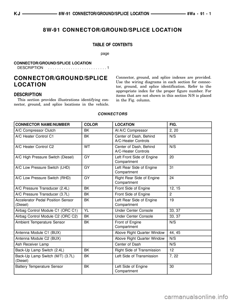
8W-91 CONNECTOR/GROUND/SPLICE LOCATION
TABLE OF CONTENTS
page
CONNECTOR/GROUND/SPLICE LOCATION
DESCRIPTION..........................1
CONNECTOR/GROUND/SPLICE
LOCATION
DESCRIPTION
This section provides illustrations identifying con-
nector, ground, and splice locations in the vehicle.Connector, ground, and splice indexes are provided.
Use the wiring diagrams in each section for connec-
tor, ground, and splice identification. Refer to the
appropriate index for the proper figure number. For
items that are not shown in this section N/S is placed
in the Fig. column.
CONNECTORS
CONNECTOR NAME/NUMBER COLOR LOCATION FIG.
A/C Compressor Clutch BK At A/C Compressor 2, 20
A/C Heater Control C1 BK Center of Dash, Behind
A/C-Heater ControlsN/S
A/C Heater Control C2 WT Center of Dash, Behind
A/C-Heater ControlsN/S
A/C High Pressure Switch (Diesel) GY Left Front Side of Engine
Compartment20
A/C Low Pressure Switch (LHD) GY Left Rear Side of Engine
Compartment31
A/C Low Pressure Switch (RHD) GY Right Rear Side of Engine
Compartment24
A/C Pressure Transducer (2.4L) BK Front Side of Engine 12, 15
A/C Pressure Transducer (3.7L) BK Front Side of Engine 2
Accelerator Pedal Position Sensor
(Diesel)BK Left Rear Side of Engine
Compartment19
Airbag Control Module C1 (ORC C1) YL Under Center Console 33, 37
Airbag Control Module C2 (ORC C2) BK Under Center Console 33, 37
Ambient Temperature Sensor BK Front of Engine
CompartmentN/S
Antenna Module C1 (BUX) Above Right Quarter Window 44, 45
Antenna Module C2 (BUX) Above Right Quarter Window N/S
Ash Receiver Lamp Center of Dash N/S
Back-Up Lamp Switch (2.4L) BK Right Side of Transmission 12
Back-Up Lamp Switch (M/T) (3.7L)
(Diesel)BK Left Side of Transmission 7, 22
Battery Temperature Sensor BK Left Side of Engine
Compartment30
KJ8W-91 CONNECTOR/GROUND/SPLICE LOCATION8Wa-91-1
Page 1161 of 1803
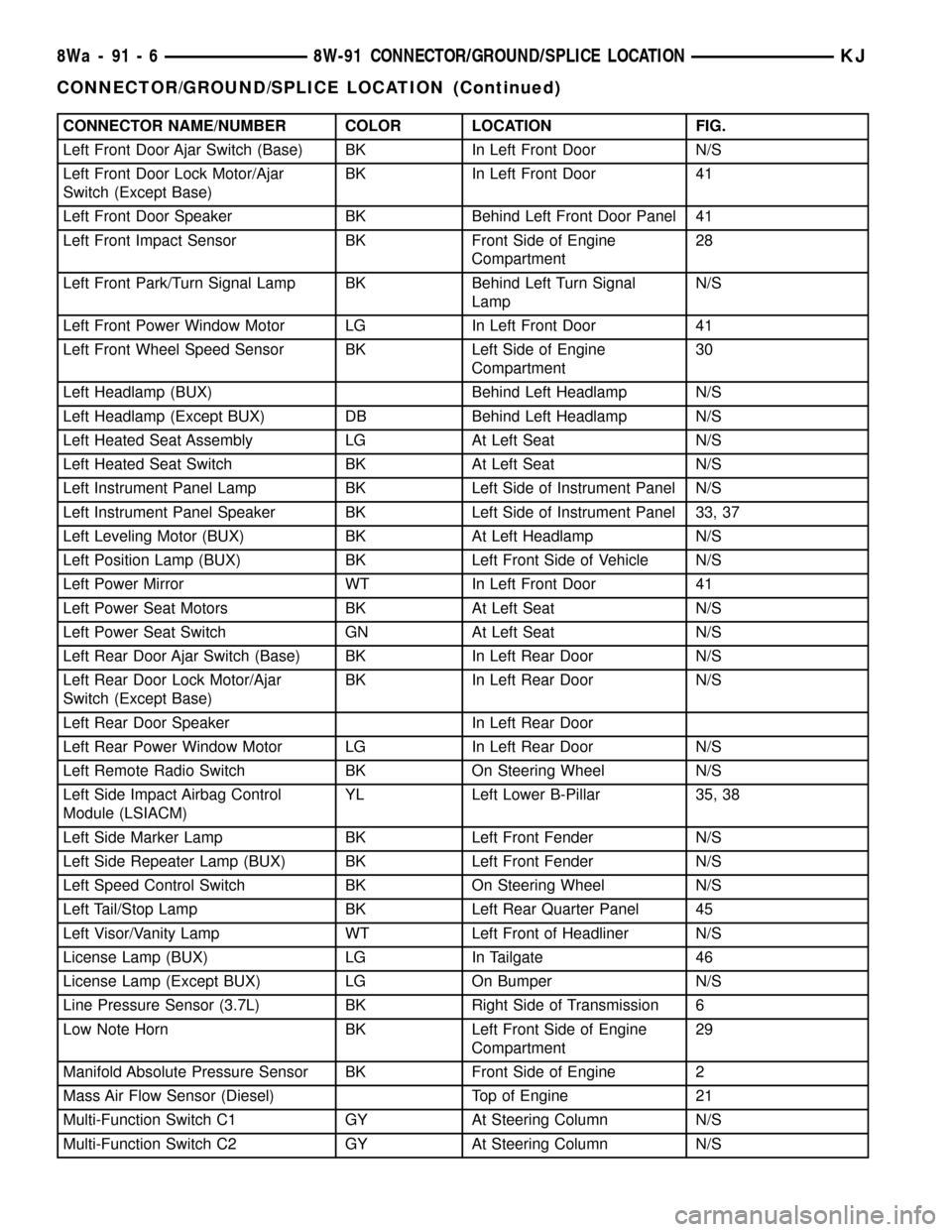
CONNECTOR NAME/NUMBER COLOR LOCATION FIG.
Left Front Door Ajar Switch (Base) BK In Left Front Door N/S
Left Front Door Lock Motor/Ajar
Switch (Except Base)BK In Left Front Door 41
Left Front Door Speaker BK Behind Left Front Door Panel 41
Left Front Impact Sensor BK Front Side of Engine
Compartment28
Left Front Park/Turn Signal Lamp BK Behind Left Turn Signal
LampN/S
Left Front Power Window Motor LG In Left Front Door 41
Left Front Wheel Speed Sensor BK Left Side of Engine
Compartment30
Left Headlamp (BUX) Behind Left Headlamp N/S
Left Headlamp (Except BUX) DB Behind Left Headlamp N/S
Left Heated Seat Assembly LG At Left Seat N/S
Left Heated Seat Switch BK At Left Seat N/S
Left Instrument Panel Lamp BK Left Side of Instrument Panel N/S
Left Instrument Panel Speaker BK Left Side of Instrument Panel 33, 37
Left Leveling Motor (BUX) BK At Left Headlamp N/S
Left Position Lamp (BUX) BK Left Front Side of Vehicle N/S
Left Power Mirror WT In Left Front Door 41
Left Power Seat Motors BK At Left Seat N/S
Left Power Seat Switch GN At Left Seat N/S
Left Rear Door Ajar Switch (Base) BK In Left Rear Door N/S
Left Rear Door Lock Motor/Ajar
Switch (Except Base)BK In Left Rear Door N/S
Left Rear Door Speaker In Left Rear Door
Left Rear Power Window Motor LG In Left Rear Door N/S
Left Remote Radio Switch BK On Steering Wheel N/S
Left Side Impact Airbag Control
Module (LSIACM)YL Left Lower B-Pillar 35, 38
Left Side Marker Lamp BK Left Front Fender N/S
Left Side Repeater Lamp (BUX) BK Left Front Fender N/S
Left Speed Control Switch BK On Steering Wheel N/S
Left Tail/Stop Lamp BK Left Rear Quarter Panel 45
Left Visor/Vanity Lamp WT Left Front of Headliner N/S
License Lamp (BUX) LG In Tailgate 46
License Lamp (Except BUX) LG On Bumper N/S
Line Pressure Sensor (3.7L) BK Right Side of Transmission 6
Low Note Horn BK Left Front Side of Engine
Compartment29
Manifold Absolute Pressure Sensor BK Front Side of Engine 2
Mass Air Flow Sensor (Diesel) Top of Engine 21
Multi-Function Switch C1 GY At Steering Column N/S
Multi-Function Switch C2 GY At Steering Column N/S
8Wa - 91 - 6 8W-91 CONNECTOR/GROUND/SPLICE LOCATIONKJ
CONNECTOR/GROUND/SPLICE LOCATION (Continued)
Page 1162 of 1803
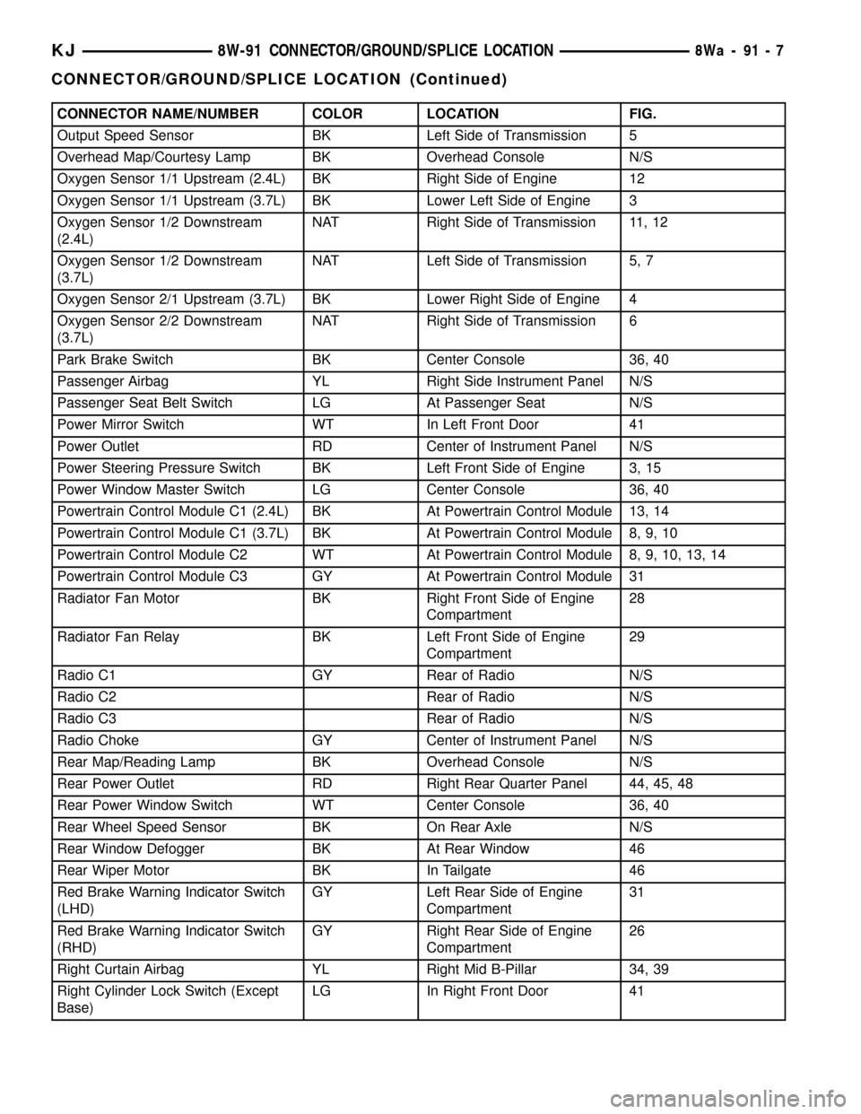
CONNECTOR NAME/NUMBER COLOR LOCATION FIG.
Output Speed Sensor BK Left Side of Transmission 5
Overhead Map/Courtesy Lamp BK Overhead Console N/S
Oxygen Sensor 1/1 Upstream (2.4L) BK Right Side of Engine 12
Oxygen Sensor 1/1 Upstream (3.7L) BK Lower Left Side of Engine 3
Oxygen Sensor 1/2 Downstream
(2.4L)NAT Right Side of Transmission 11, 12
Oxygen Sensor 1/2 Downstream
(3.7L)NAT Left Side of Transmission 5, 7
Oxygen Sensor 2/1 Upstream (3.7L) BK Lower Right Side of Engine 4
Oxygen Sensor 2/2 Downstream
(3.7L)NAT Right Side of Transmission 6
Park Brake Switch BK Center Console 36, 40
Passenger Airbag YL Right Side Instrument Panel N/S
Passenger Seat Belt Switch LG At Passenger Seat N/S
Power Mirror Switch WT In Left Front Door 41
Power Outlet RD Center of Instrument Panel N/S
Power Steering Pressure Switch BK Left Front Side of Engine 3, 15
Power Window Master Switch LG Center Console 36, 40
Powertrain Control Module C1 (2.4L) BK At Powertrain Control Module 13, 14
Powertrain Control Module C1 (3.7L) BK At Powertrain Control Module 8, 9, 10
Powertrain Control Module C2 WT At Powertrain Control Module 8, 9, 10, 13, 14
Powertrain Control Module C3 GY At Powertrain Control Module 31
Radiator Fan Motor BK Right Front Side of Engine
Compartment28
Radiator Fan Relay BK Left Front Side of Engine
Compartment29
Radio C1 GY Rear of Radio N/S
Radio C2 Rear of Radio N/S
Radio C3 Rear of Radio N/S
Radio Choke GY Center of Instrument Panel N/S
Rear Map/Reading Lamp BK Overhead Console N/S
Rear Power Outlet RD Right Rear Quarter Panel 44, 45, 48
Rear Power Window Switch WT Center Console 36, 40
Rear Wheel Speed Sensor BK On Rear Axle N/S
Rear Window Defogger BK At Rear Window 46
Rear Wiper Motor BK In Tailgate 46
Red Brake Warning Indicator Switch
(LHD)GY Left Rear Side of Engine
Compartment31
Red Brake Warning Indicator Switch
(RHD)GY Right Rear Side of Engine
Compartment26
Right Curtain Airbag YL Right Mid B-Pillar 34, 39
Right Cylinder Lock Switch (Except
Base)LG In Right Front Door 41
KJ8W-91 CONNECTOR/GROUND/SPLICE LOCATION8Wa-91-7
CONNECTOR/GROUND/SPLICE LOCATION (Continued)
Page 1163 of 1803
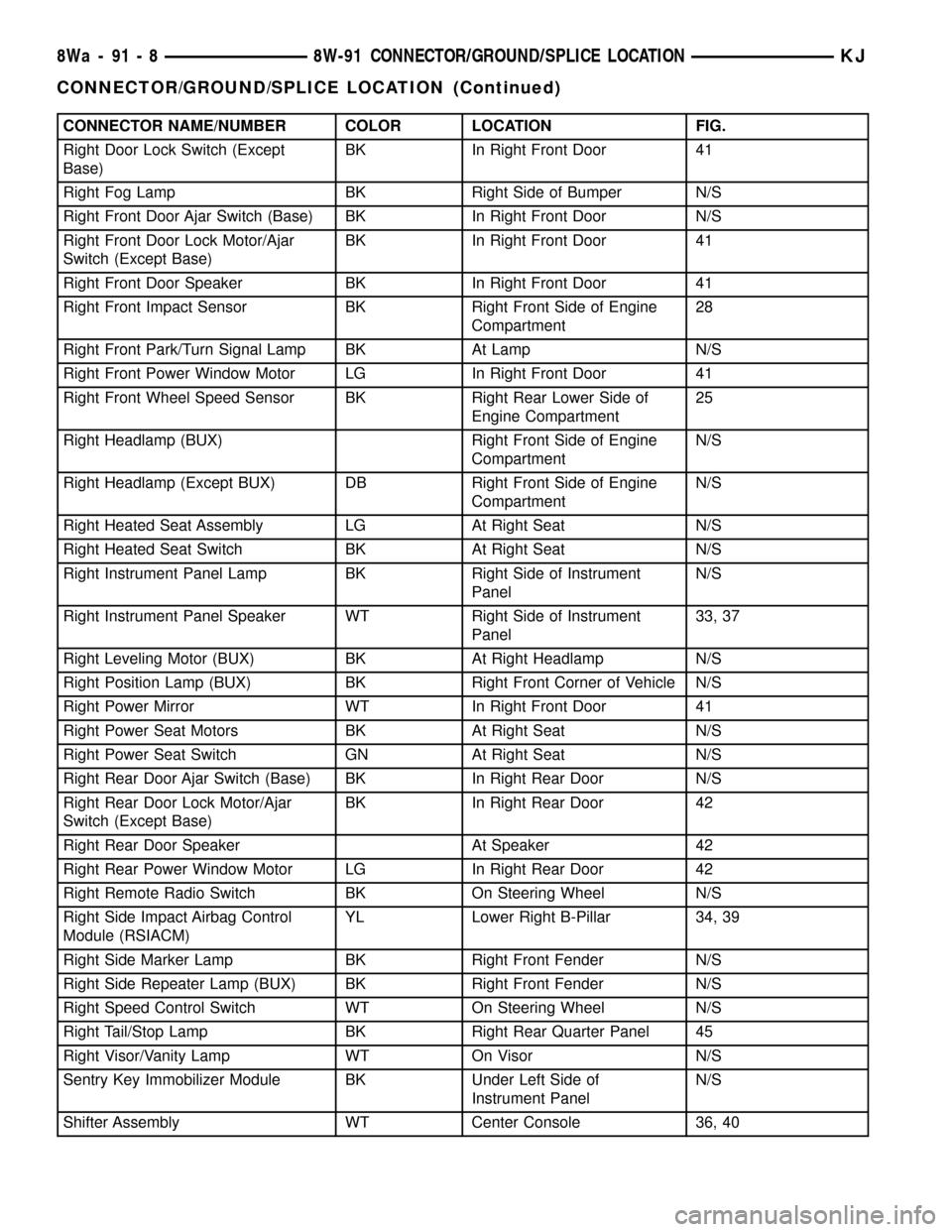
CONNECTOR NAME/NUMBER COLOR LOCATION FIG.
Right Door Lock Switch (Except
Base)BK In Right Front Door 41
Right Fog Lamp BK Right Side of Bumper N/S
Right Front Door Ajar Switch (Base) BK In Right Front Door N/S
Right Front Door Lock Motor/Ajar
Switch (Except Base)BK In Right Front Door 41
Right Front Door Speaker BK In Right Front Door 41
Right Front Impact Sensor BK Right Front Side of Engine
Compartment28
Right Front Park/Turn Signal Lamp BK At Lamp N/S
Right Front Power Window Motor LG In Right Front Door 41
Right Front Wheel Speed Sensor BK Right Rear Lower Side of
Engine Compartment25
Right Headlamp (BUX) Right Front Side of Engine
CompartmentN/S
Right Headlamp (Except BUX) DB Right Front Side of Engine
CompartmentN/S
Right Heated Seat Assembly LG At Right Seat N/S
Right Heated Seat Switch BK At Right Seat N/S
Right Instrument Panel Lamp BK Right Side of Instrument
PanelN/S
Right Instrument Panel Speaker WT Right Side of Instrument
Panel33, 37
Right Leveling Motor (BUX) BK At Right Headlamp N/S
Right Position Lamp (BUX) BK Right Front Corner of Vehicle N/S
Right Power Mirror WT In Right Front Door 41
Right Power Seat Motors BK At Right Seat N/S
Right Power Seat Switch GN At Right Seat N/S
Right Rear Door Ajar Switch (Base) BK In Right Rear Door N/S
Right Rear Door Lock Motor/Ajar
Switch (Except Base)BK In Right Rear Door 42
Right Rear Door Speaker At Speaker 42
Right Rear Power Window Motor LG In Right Rear Door 42
Right Remote Radio Switch BK On Steering Wheel N/S
Right Side Impact Airbag Control
Module (RSIACM)YL Lower Right B-Pillar 34, 39
Right Side Marker Lamp BK Right Front Fender N/S
Right Side Repeater Lamp (BUX) BK Right Front Fender N/S
Right Speed Control Switch WT On Steering Wheel N/S
Right Tail/Stop Lamp BK Right Rear Quarter Panel 45
Right Visor/Vanity Lamp WT On Visor N/S
Sentry Key Immobilizer Module BK Under Left Side of
Instrument PanelN/S
Shifter Assembly WT Center Console 36, 40
8Wa - 91 - 8 8W-91 CONNECTOR/GROUND/SPLICE LOCATIONKJ
CONNECTOR/GROUND/SPLICE LOCATION (Continued)
Page 1168 of 1803
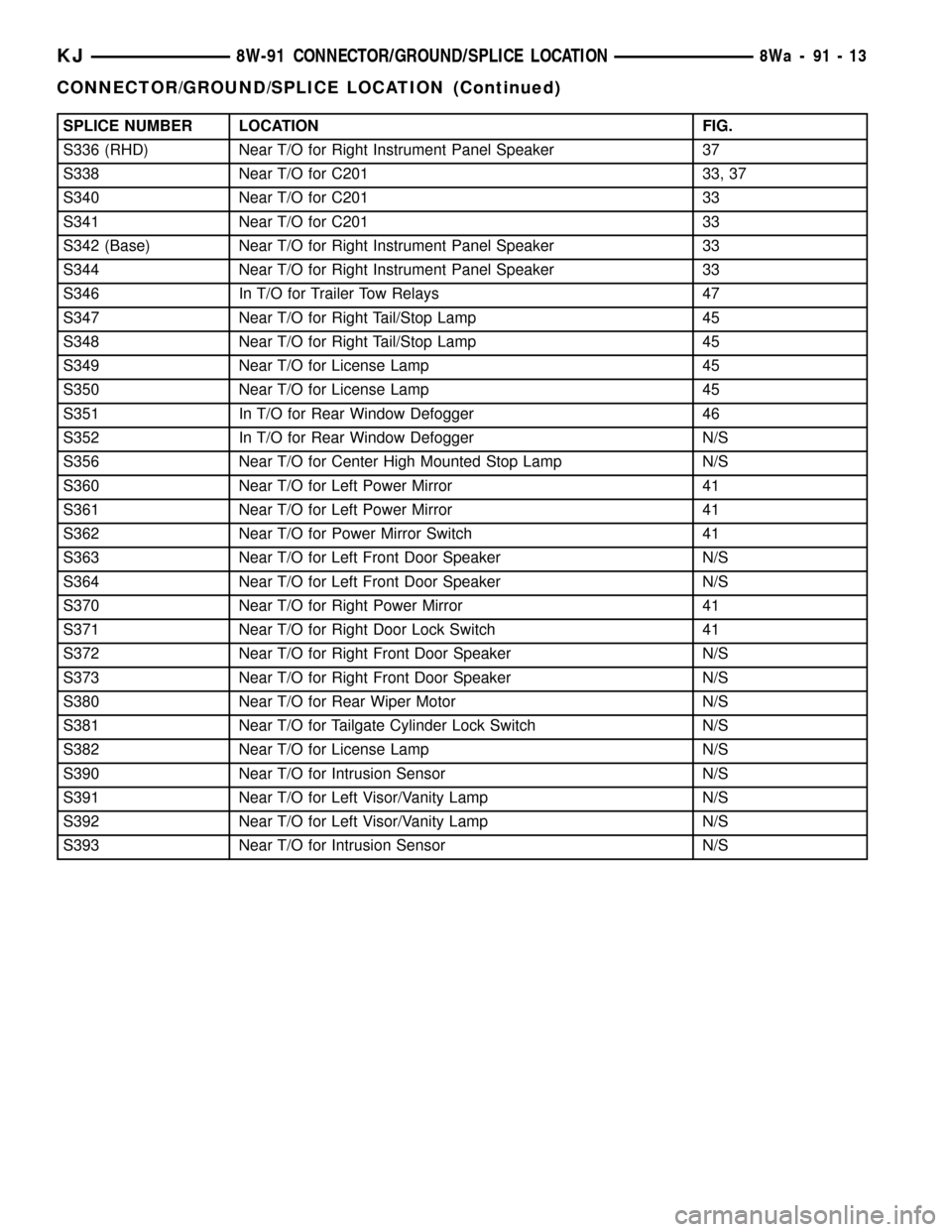
SPLICE NUMBER LOCATION FIG.
S336 (RHD) Near T/O for Right Instrument Panel Speaker 37
S338 Near T/O for C201 33, 37
S340 Near T/O for C201 33
S341 Near T/O for C201 33
S342 (Base) Near T/O for Right Instrument Panel Speaker 33
S344 Near T/O for Right Instrument Panel Speaker 33
S346 In T/O for Trailer Tow Relays 47
S347 Near T/O for Right Tail/Stop Lamp 45
S348 Near T/O for Right Tail/Stop Lamp 45
S349 Near T/O for License Lamp 45
S350 Near T/O for License Lamp 45
S351 In T/O for Rear Window Defogger 46
S352 In T/O for Rear Window Defogger N/S
S356 Near T/O for Center High Mounted Stop Lamp N/S
S360 Near T/O for Left Power Mirror 41
S361 Near T/O for Left Power Mirror 41
S362 Near T/O for Power Mirror Switch 41
S363 Near T/O for Left Front Door Speaker N/S
S364 Near T/O for Left Front Door Speaker N/S
S370 Near T/O for Right Power Mirror 41
S371 Near T/O for Right Door Lock Switch 41
S372 Near T/O for Right Front Door Speaker N/S
S373 Near T/O for Right Front Door Speaker N/S
S380 Near T/O for Rear Wiper Motor N/S
S381 Near T/O for Tailgate Cylinder Lock Switch N/S
S382 Near T/O for License Lamp N/S
S390 Near T/O for Intrusion Sensor N/S
S391 Near T/O for Left Visor/Vanity Lamp N/S
S392 Near T/O for Left Visor/Vanity Lamp N/S
S393 Near T/O for Intrusion Sensor N/S
KJ8W-91 CONNECTOR/GROUND/SPLICE LOCATION8Wa-91-13
CONNECTOR/GROUND/SPLICE LOCATION (Continued)
Page 1588 of 1803

EXTERIOR HANDLE
REMOVAL
(1) Remove the door glass. (Refer to 23 - BODY/
DOOR - FRONT/DOOR GLASS - REMOVAL)
(2) Disconnect the lock switch electrical connector,
if equipped. (Fig. 4)
(3) Disconnect the handle rod at the handle and
the key cylinder rod at the latch.
(4) Remove the screws.
(5) Remove the nuts and remove the handle.
INSTALLATION
(1) Position the handle on the door and slide fully
toward the rear of the door.
(2) Install the nuts and tighten to 6 N´m (55 in.
lbs.).
(3) Install the screws and tighten to 6 N´m (55 in.
lbs.).
(4) Connect the handle rod at the handle and the
key cylinder rod at the latch.
(5) Connect the lock switch electrical connector, if
equipped.
(6) Install the door glass. (Refer to 23 - BODY/
DOOR - FRONT/DOOR GLASS - INSTALLATION)
GLASS RUN CHANNEL
REMOVAL
(1) Position the window into the down position.
(2) Remove the waterdam. (Refer to 23 - BODY/
DOOR - FRONT/WATERDAM - REMOVAL)(3) Remove the outer belt molding. (Refer to 23 -
BODY/WEATHERSTRIP/SEALS/FRONT DOOR
OUTER BELT MOLDING - REMOVAL)
(4) Remove the front and rear bolts. (Fig. 5)
(5) Peal the weatherstrip out of the door frame
and remove the run channel through the window
opening.
INSTALLATION
(1) Install the run channel through the window
opening and into the door frame.
(2) Install the front, rear bolts and tighten to 9
N´m (80 in. lbs.).
(3) Install the outer belt molding. (Refer to 23 -
BODY/WEATHERSTRIP/SEALS/FRONT DOOR
OUTER BELT MOLDING - INSTALLATION)
(4) Install the waterdam. (Refer to 23 - BODY/
DOOR - FRONT/WATERDAM - INSTALLATION)
HINGE
REMOVAL
(1) Remove the door. (Refer to 23 - BODY/DOOR -
FRONT/DOOR - REMOVAL)
(2) Using a grease pencil or equivalent, mark the
hinge location and remove the bolts.
INSTALLATION
(1) Install the hinges and bolts.
(2) Tighten bolts to 28 N´m (21 ft. lbs.).
(3) Install the door. (Refer to 23 - BODY/DOOR -
FRONT/DOOR - INSTALLATION)
Fig. 4 EXTERIOR HANDLE
1 - EXTERIOR HANDLE
2 - NUTS
3 - SCREWS
4 - ELECTRICAL CONNECTOR
Fig. 5 GLASS RUN CHANNEL
1 - WINDOW OPENING
2 - REAR BOLTS (2)
3 - GLASS RUN CHANNEL
4 - FRONT BOLTS (2)
KJDOOR - FRONT 23 - 123
Page 1655 of 1803
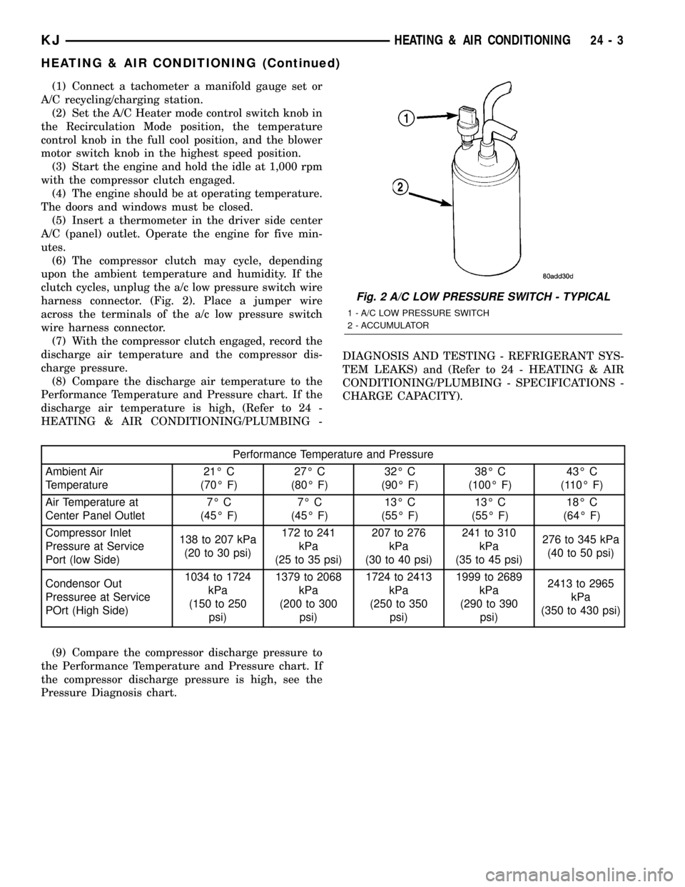
(1) Connect a tachometer a manifold gauge set or
A/C recycling/charging station.
(2) Set the A/C Heater mode control switch knob in
the Recirculation Mode position, the temperature
control knob in the full cool position, and the blower
motor switch knob in the highest speed position.
(3) Start the engine and hold the idle at 1,000 rpm
with the compressor clutch engaged.
(4) The engine should be at operating temperature.
The doors and windows must be closed.
(5) Insert a thermometer in the driver side center
A/C (panel) outlet. Operate the engine for five min-
utes.
(6) The compressor clutch may cycle, depending
upon the ambient temperature and humidity. If the
clutch cycles, unplug the a/c low pressure switch wire
harness connector. (Fig. 2). Place a jumper wire
across the terminals of the a/c low pressure switch
wire harness connector.
(7) With the compressor clutch engaged, record the
discharge air temperature and the compressor dis-
charge pressure.
(8) Compare the discharge air temperature to the
Performance Temperature and Pressure chart. If the
discharge air temperature is high, (Refer to 24 -
HEATING & AIR CONDITIONING/PLUMBING -DIAGNOSIS AND TESTING - REFRIGERANT SYS-
TEM LEAKS) and (Refer to 24 - HEATING & AIR
CONDITIONING/PLUMBING - SPECIFICATIONS -
CHARGE CAPACITY).
Performance Temperature and Pressure
Ambient Air
Temperature21É C
(70É F)27É C
(80É F)32É C
(90É F)38É C
(100É F)43É C
(110É F)
Air Temperature at
Center Panel Outlet7É C
(45É F)7É C
(45É F)13É C
(55É F)13É C
(55É F)18É C
(64É F)
Compressor Inlet
Pressure at Service
Port (low Side)138 to 207 kPa
(20 to 30 psi)172 to 241
kPa
(25 to 35 psi)207 to 276
kPa
(30 to 40 psi)241 to 310
kPa
(35 to 45 psi)276 to 345 kPa
(40 to 50 psi)
Condensor Out
Pressuree at Service
POrt (High Side)1034 to 1724
kPa
(150 to 250
psi)1379 to 2068
kPa
(200 to 300
psi)1724 to 2413
kPa
(250 to 350
psi)1999 to 2689
kPa
(290 to 390
psi)2413 to 2965
kPa
(350 to 430 psi)
(9) Compare the compressor discharge pressure to
the Performance Temperature and Pressure chart. If
the compressor discharge pressure is high, see the
Pressure Diagnosis chart.
Fig. 2 A/C LOW PRESSURE SWITCH - TYPICAL
1 - A/C LOW PRESSURE SWITCH
2 - ACCUMULATOR
KJHEATING & AIR CONDITIONING 24 - 3
HEATING & AIR CONDITIONING (Continued)
Page 1668 of 1803

(2) Resistance between terminals 85 and 86 (elec-
tromagnet) should be 67.5 to 82.5 ohms. If OK, go to
Step 3. If not OK, replace the faulty relay.
(3) Connect a battery to terminals 85 and 86.
There should now be continuity between terminals
30 and 87, and no continuity between terminals 87A
and 30. If OK, see Relay Circuit Test. If not OK,
replace the faulty relay.
RELAY CIRCUIT TEST
For circuit descriptions and diagrams, (Refer to
Appropriate Wiring Information).
(1) The relay common feed terminal cavity (30) is
connected to fused battery feed. There should be bat-
tery voltage at the cavity for relay terminal 30 at all
times. If OK, go to Step 2. If not OK, repair the open
circuit to the fuse in the PDC as required.
(2) The relay normally closed terminal (87A) is not
used in this application. Go to Step 3.
(3) The relay normally open terminal cavity (87) is
connected to the compressor clutch coil. There should
be continuity between this cavity and the A/C com-
pressor clutch relay output circuit cavity of the com-
pressor clutch coil wire harness connector. If OK, go
to Step 4. If not OK, repair the open circuit as
required.
(4) The relay coil battery terminal (86) is con-
nected to the fused ignition switch output (run/start)circuit. There should be battery voltage at the cavity
for relay terminal 86 with the ignition switch in the
On position. If OK, go to Step 5. If not OK, repair the
open circuit to the fuse in the junction block as
required.
(5) The coil ground terminal cavity (85) is switched
to ground through the Powertrain Control Module
(PCM). There should be continuity between this cav-
ity and the A/C compressor clutch relay control cir-
cuit cavity of the PCM wire harness connector C
(gray) at all times. If not OK, repair the open circuit
as required.
REMOVAL
(1) Disconnect and isolate the battery negative
cable.
(2) Remove the cover from the Power Distribution
Center (PDC).
(3) Refer to the label on the PDC for compressor
clutch relay identification and location.
(4) Unplug the compressor clutch relay from the
PDC.
INSTALLATION
(1) Install the compressor clutch relay by aligning
the relay terminals with the cavities in the PDC and
pushing the relay firmly into place.
(2) Install the PDC cover.
(3) Connect the battery negative cable.
(4) Test the relay operation.
A/C HEATER CONTROL
DESCRIPTION
Both the heater-only and A/C heater systems use a
combination of mechanical, electrical, and vacuum
controls. These controls provide the vehicle operator
with a number of setting options to help control the
climate and comfort within the vehicle. Refer to the
owner's manual in the vehicle glove box for more
information on the features, use, and suggested oper-
ation of these controls.
The heater-only or A/C heater control panel is
located to the right of the instrument cluster on the
instrument panel. The control panel contains a rota-
ry-type temperature control knob, a rotary-type mode
control switch knob, and a rotary-type blower motor
speed switch knob. The control also has a push but-
ton to activate the rear window defogger.
The heater-only or A/C heater control panel cannot
be repaired. If faulty or damaged, the entire unit
must be replaced. The illumination lamps are avail-
able for service replacement.
Fig. 10 COMPRESSOR CLUTCH RELAY
30 - COMMON FEED
85 - COIL GROUND
86 - COIL BATTERY
87 - NORMALLY OPEN
87A - NORMALLY CLOSED
24 - 16 CONTROLSKJ
A/C COMPRESSOR CLUTCH RELAY (Continued)