2002 JEEP LIBERTY lock
[x] Cancel search: lockPage 150 of 1803

AXLE SHAFTS
REMOVAL
(1) Place the transmission in NEUTRAL and raise
and support vehicle.
(2) Remove wheel and tire assembly.
(3) Remove brake drum.
(4) Remove the housing cover and drain lubricant.
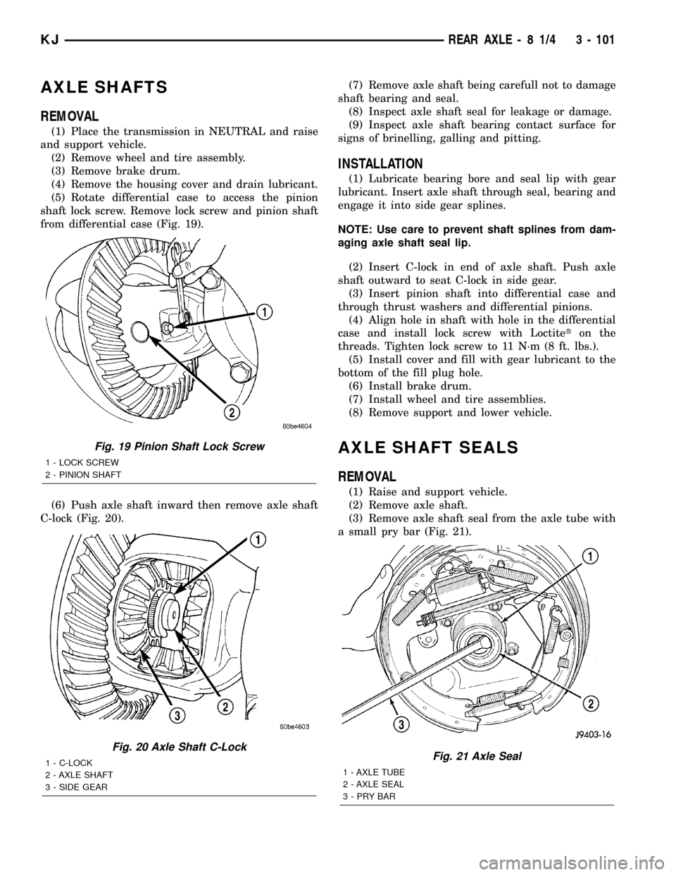
(5) Rotate differential case to access the pinion
shaft lock screw. Remove lock screw and pinion shaft
from differential case (Fig. 19).
(6) Push axle shaft inward then remove axle shaft
C-lock (Fig. 20).(7) Remove axle shaft being carefull not to damage
shaft bearing and seal.
(8) Inspect axle shaft seal for leakage or damage.
(9) Inspect axle shaft bearing contact surface for
signs of brinelling, galling and pitting.
INSTALLATION
(1) Lubricate bearing bore and seal lip with gear
lubricant. Insert axle shaft through seal, bearing and
engage it into side gear splines.
NOTE: Use care to prevent shaft splines from dam-
aging axle shaft seal lip.
(2) Insert C-lock in end of axle shaft. Push axle
shaft outward to seat C-lock in side gear.
(3) Insert pinion shaft into differential case and
through thrust washers and differential pinions.
(4) Align hole in shaft with hole in the differential
case and install lock screw with Loctiteton the
threads. Tighten lock screw to 11 N´m (8 ft. lbs.).
(5) Install cover and fill with gear lubricant to the
bottom of the fill plug hole.
(6) Install brake drum.
(7) Install wheel and tire assemblies.
(8) Remove support and lower vehicle.
AXLE SHAFT SEALS
REMOVAL
(1) Raise and support vehicle.
(2) Remove axle shaft.
(3) Remove axle shaft seal from the axle tube with
a small pry bar (Fig. 21).
Fig. 19 Pinion Shaft Lock Screw
1 - LOCK SCREW
2 - PINION SHAFT
Fig. 20 Axle Shaft C-Lock
1 - C-LOCK
2 - AXLE SHAFT
3 - SIDE GEARFig. 21 Axle Seal
1 - AXLE TUBE
2 - AXLE SEAL
3-PRYBAR
KJREAR AXLE - 8 1/4 3 - 101
Page 153 of 1803

lbs.) increments until proper rotating torque is
achieved.
NOTE: The bearing rotating torque should be con-
stant during a complete revolution of the pinion. If
the rotating torque varies, it indicates a binding
condition.
(9) The seal replacement is unacceptable if the
final pinion nut torque is less than 285 N´m (210 ft.
lbs.).
(10) Install the propeller shaft with the installa-
tion reference marks aligned.
(11) Install the brake drums.
(12) Check the differential housing lubricant level.
(13) Install wheel and tire assemblies and lower
the vehicle.
DIFFERENTIAL
REMOVAL
(1) Raise and support vehicle.
(2) Remove fill hole plug from the differential
housing cover.
(3) Remove differential housing cover and drain
housing.
(4) Clean the housing cavity with a flushing oil,
light engine oil or lint free cloth.Do not use water,
steam, kerosene or gasoline for cleaning.(5) Remove the axle shafts.
NOTE: Side play resulting from bearing races being
loose on case hubs requires replacement of the dif-
ferential case.
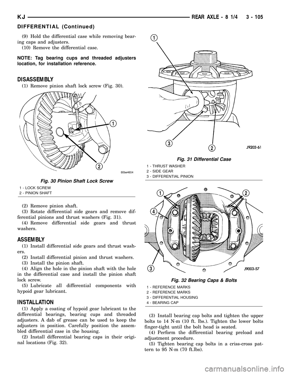
(6) Mark the differential housing and bearing caps
for installation reference (Fig. 28).
(7) Remove bearing threaded adjuster locks from
each bearing cap.
(8) Loosen bearing cap bolts, them loosen the
threaded adjusters with Wrench C-4164 (Fig. 29).
Fig. 27 Pinion Rotation Torque
1 - PINION YOKE
2 - INCH POUND TORQUE WRENCH
Fig. 28 Reference Mark
1 - REFERENCE MARKS
2 - REFERENCE MARKS
3 - DIFFERENTIAL HOUSING
4 - BEARING CAP
Fig. 29 Threaded Adjuster
1 - AXLE TUBE
2 - BACKING PLATE
3 - THREAD ADJUSTER WRENCH
3 - 104 REAR AXLE-81/4KJ
PINION SEAL (Continued)
Page 154 of 1803

(9) Hold the differential case while removing bear-
ing caps and adjusters.
(10) Remove the differential case.
NOTE: Tag bearing cups and threaded adjusters
location, for installation reference.
DISASSEMBLY
(1) Remove pinion shaft lock screw (Fig. 30).
(2) Remove pinion shaft.
(3) Rotate differential side gears and remove dif-
ferential pinions and thrust washers (Fig. 31).
(4) Remove differential side gears and thrust
washers.
ASSEMBLY
(1) Install differential side gears and thrust wash-
ers.
(2) Install differential pinion and thrust washers.
(3) Install the pinion shaft.
(4) Align the hole in the pinion shaft with the hole
in the differential case and install the pinion shaft
lock screw.
(5) Lubricate all differential components with
hypoid gear lubricant.
INSTALLATION
(1) Apply a coating of hypoid gear lubricant to the
differential bearings, bearing cups and threaded
adjusters. A dab of grease can be used to keep the
adjusters in position. Carefully position the assem-
bled differential case in the housing.
(2) Install differential bearing caps in their origi-
nal locations (Fig. 32).(3) Install bearing cap bolts and tighten the upper
bolts to 14 N´m (10 ft. lbs.). Tighten the lower bolts
finger-tight until the bolt head is seated.
(4) Perform the differential bearing preload and
adjustment procedure.
(5) Tighten bearing cap bolts in a criss-cross pat-
tern to 95 N´m (70 ft.lbs).
Fig. 30 Pinion Shaft Lock Screw
1 - LOCK SCREW
2 - PINION SHAFT
Fig. 31 Differential Case
1 - THRUST WASHER
2 - SIDE GEAR
3 - DIFFERENTIAL PINION
Fig. 32 Bearing Caps & Bolts
1 - REFERENCE MARKS
2 - REFERENCE MARKS
3 - DIFFERENTIAL HOUSING
4 - BEARING CAP
KJREAR AXLE - 8 1/4 3 - 105
DIFFERENTIAL (Continued)
Page 155 of 1803

(6) Install adjuster locks on the bearing caps.
(7) Install axle shafts.
(8) Apply a bead of red Mopar silicone rubber axle
sealant or equivalent to the housing cover (Fig. 33).
CAUTION: If cover is not installed within 3 to 5 min-
utes, the cover must be cleaned and new RTV
applied or adhesion quality will be compromised.
(9) Install cover and tighten bolts in a criss-cross
pattern to 41 N´m (30 ft. lbs.).
(10) Fill differential with gear lubricant to bottom
of the fill plug hole.
(11) Install the fill hole plug.
(12) Install wheel and tire assemblies.
(13) Remove support and lower vehicle.
(14) Trac-loktdifferential equipped vehicles should
be road tested by making 10 to 12 slow figure-eight
turns. This maneuver will pump the lubricant
through the clutch discs to eliminate a possible chat-
ter noise complaint.DIFFERENTIAL - TRAC-LOK
DIAGNOSIS AND TESTING - TRAC-LOKT
The most common problem is a chatter noise when
turning corners. Before removing the unit for repair,
drain, flush and refill the axle with the specified
lubricant. A container of Mopar Trac-loktLubricant
(friction modifier) should be added after repair ser-
vice or during a lubricant change.
After changing the lubricant, drive the vehicle and
make 10 to 12 slow, figure-eight turns. This maneu-
ver will pump lubricant through the clutches. This
will correct the condition in most instances. If the
chatter persists, clutch damage could have occurred.
DIFFERENTIAL TEST
The differential can be tested without removing the
differential case by measuring rotating torque. Make
sure brakes are not dragging during this measure-
ment.
(1) Place blocks in front and rear of both front
wheels.
(2) Raise one rear wheel until it is completely off
the ground.
(3) Engine off, transmission in neutral, and park-
ing brake off.
(4) Remove wheel and bolt Special Tool 6790 or
equivalent tool to studs.
(5) Use torque wrench on special tool to rotate
wheel and read rotating torque (Fig. 34).
(6) If rotating torque is less than 41 N´m (56 ft.
lbs.) or more than 271 N´m (200 ft. lbs.) on either
wheel the unit should be serviced.
Fig. 33 Differential Cover Sealant
1 - SEALANT
2 - DIFFERNTIAL COVER
Fig. 34 ROTATING TORQUE TEST
1 - SPECIAL TOOL WITH BOLT IN CENTER HOLE
2 - TORQUE WRENCH
3 - 106 REAR AXLE-81/4KJ
DIFFERENTIAL (Continued)
Page 156 of 1803

DISASSEMBLY
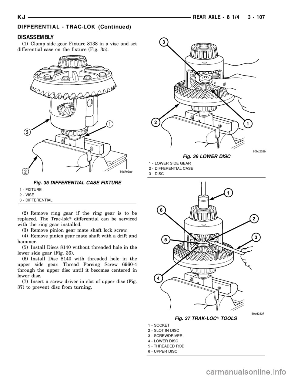
(1) Clamp side gear Fixture 8138 in a vise and set
differential case on the fixture (Fig. 35).
(2) Remove ring gear if the ring gear is to be
replaced. The Trac-loktdifferential can be serviced
with the ring gear installed.
(3) Remove pinion gear mate shaft lock screw.
(4) Remove pinion gear mate shaft with a drift and
hammer.
(5) Install Discs 8140 without threaded hole in the
lower side gear (Fig. 36).
(6) Install Disc 8140 with threaded hole in the
upper side gear. Thread Forcing Screw 6960-4
through the upper disc until it becomes centered in
lower disc.
(7) Insert a screw driver in slot of upper disc (Fig.
37) to prevent disc from turning.
Fig. 36 LOWER DISC
1 - LOWER SIDE GEAR
2 - DIFFERENTIAL CASE
3 - DISC
Fig. 37 TRAK-LOCTTOOLS
1 - SOCKET
2 - SLOT IN DISC
3 - SCREWDRIVER
4 - LOWER DISC
5 - THREADED ROD
6 - UPPER DISC
Fig. 35 DIFFERENTIAL CASE FIXTURE
1 - FIXTURE
2 - VISE
3 - DIFFERENTIAL
KJREAR AXLE - 8 1/4 3 - 107
DIFFERENTIAL - TRAC-LOK (Continued)
Page 159 of 1803

(14) Install pinion gear mate shaft and align holes
in shaft and case.
(15) Install pinion mate shaft lock screw finger
tight to hold shaft during differential installation.
(16) Lubricate all differential components with
hypoid gear lubricant.
DIFFERENTIAL CASE
BEARINGS
REMOVAL
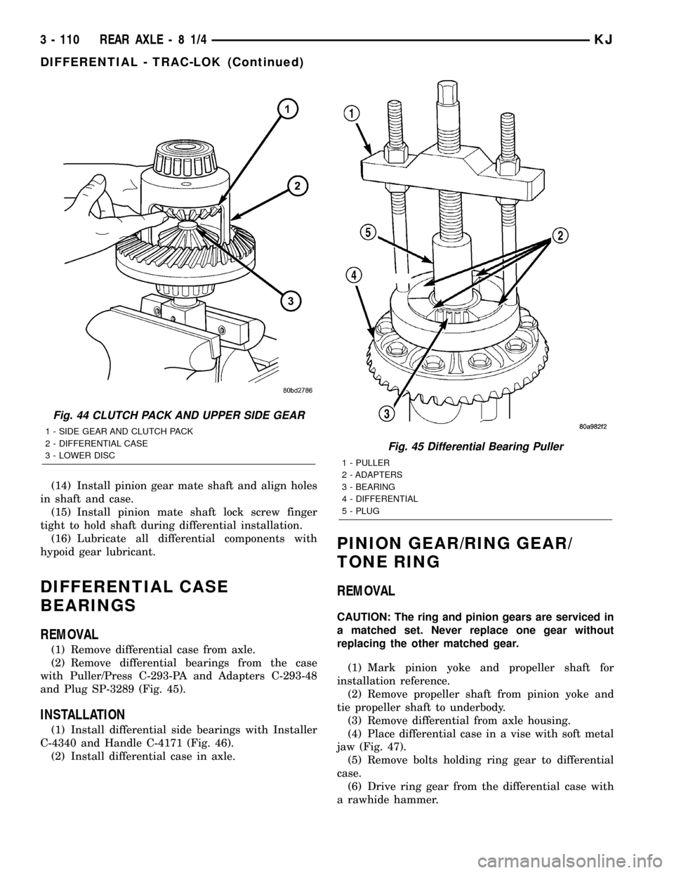
(1) Remove differential case from axle.
(2) Remove differential bearings from the case
with Puller/Press C-293-PA and Adapters C-293-48
and Plug SP-3289 (Fig. 45).
INSTALLATION
(1) Install differential side bearings with Installer
C-4340 and Handle C-4171 (Fig. 46).
(2) Install differential case in axle.
PINION GEAR/RING GEAR/
TONE RING
REMOVAL
CAUTION: The ring and pinion gears are serviced in
a matched set. Never replace one gear without
replacing the other matched gear.
(1) Mark pinion yoke and propeller shaft for
installation reference.
(2) Remove propeller shaft from pinion yoke and
tie propeller shaft to underbody.
(3) Remove differential from axle housing.
(4) Place differential case in a vise with soft metal
jaw (Fig. 47).
(5) Remove bolts holding ring gear to differential
case.
(6) Drive ring gear from the differential case with
a rawhide hammer.
Fig. 44 CLUTCH PACK AND UPPER SIDE GEAR
1 - SIDE GEAR AND CLUTCH PACK
2 - DIFFERENTIAL CASE
3 - LOWER DISC
Fig. 45 Differential Bearing Puller
1 - PULLER
2 - ADAPTERS
3 - BEARING
4 - DIFFERENTIAL
5 - PLUG
3 - 110 REAR AXLE-81/4KJ
DIFFERENTIAL - TRAC-LOK (Continued)
Page 165 of 1803

BRAKES
TABLE OF CONTENTS
page page
BRAKES - BASE........................... 1BRAKES - ABS........................... 32
BRAKES - BASE
TABLE OF CONTENTS
page page
BRAKES - BASE
DESCRIPTION..........................2
WARNING.............................2
DIAGNOSIS AND TESTING - BASE BRAKE
SYSTEM.............................3
STANDARD PROCEDURE
STANDARD PROCEDURE - PRESSURE
BLEEDING............................5
STANDARD PROCEDURE - MANUAL
BLEEDING............................6
SPECIFICATIONS
BRAKE COMPONENTS..................6
TORQUE.............................7
SPECIAL TOOLS
BASE BRAKES........................7
BRAKE LINES
DESCRIPTION..........................8
DIAGNOSIS AND TESTING - BRAKE LINE
AND HOSES..........................8
STANDARD PROCEDURE
STANDARD PROCEDURE - DOUBLE
INVERTED FLARING....................8
STANDARD PROCEDURE - ISO FLARING . . . 8
REMOVAL
REMOVAL - FRONT HOSE...............9
REMOVAL - REAR BRAKE HOSE..........9
INSTALLATION
INSTALLATION - FRONT BRAKE HOSE....10
INSTALLATION - REAR BRAKE HOSE......10
BRAKE PADS / SHOES
DESCRIPTION - REAR DRUM BRAKE.......10
OPERATION - REAR DRUM BRAKE.........11
REMOVAL
REMOVAL - FRONT BRAKE PADS.........11
REMOVAL - DRUM BRAKE SHOES........11
INSTALLATION
INSTALLATION - FRONT BRAKE PADS.....11INSTALLATION - DRUM BRAKE SHOES....11
ADJUSTMENTS
ADJUSTMENT - REAR DRUM BRAKE......12
DISC BRAKE CALIPERS
DESCRIPTION.........................13
OPERATION...........................14
REMOVAL.............................14
DISASSEMBLY.........................14
CLEANING............................16
INSPECTION..........................16
ASSEMBLY............................16
INSTALLATION.........................17
DISC BRAKE CALIPER ADAPTER
REMOVAL.............................18
INSTALLATION.........................18
ROTORS
DIAGNOSIS AND TESTING - DISC BRAKE
ROTOR .............................18
STANDARD PROCEDURE - DISC BRAKE
ROTOR .............................19
REMOVAL.............................19
INSTALLATION.........................19
JUNCTION BLOCK
DESCRIPTION.........................20
OPERATION...........................20
DIAGNOSIS AND TESTING -
PROPORTIONING VALVE...............20
REMOVAL.............................20
INSTALLATION.........................20
PEDAL
DESCRIPTION.........................20
OPERATION...........................20
REMOVAL.............................20
INSTALLATION.........................20
POWER BRAKE BOOSTER
DESCRIPTION.........................21
OPERATION...........................21
KJBRAKES 5 - 1
Page 166 of 1803

DIAGNOSIS AND TESTING - MASTER
CYLINDER/POWER BOOSTER...........21
REMOVAL.............................22
INSTALLATION.........................23
MASTER CYLINDER
DESCRIPTION.........................24
OPERATION...........................24
DIAGNOSIS AND TESTING - MASTER
CYLINDER/POWER BOOSTER...........24
STANDARD PROCEDURE - MASTER
CYLINDER BLEEDING..................24
REMOVAL.............................25
INSTALLATION.........................25
FLUID RESERVOIR
REMOVAL.............................26
INSTALLATION.........................26
FLUID
DIAGNOSIS AND TESTING - BRAKE FLUID
CONTAMINATION.....................26
STANDARD PROCEDURES - MASTER
CYLINDER FLUID LEVEL................26
SPECIFICATIONS
BRAKE FLUID........................27
DRUM
DIAGNOSIS AND TESTING - BRAKE DRUM . . . 27
STANDARD PROCEDURES - BRAKE DRUM
MACHINING..........................27SUPPORT PLATE
REMOVAL
REMOVAL - 198 RBI AXLE..............27
REMOVAL - 8 1/4 AXLE.................27
INSTALLATION
INSTALLATION - 198 RBI AXLE...........28
INSTALLATION - 8 1/4 AXLE.............28
WHEEL CYLINDERS
REMOVAL.............................28
DISASSEMBLY.........................28
CLEANING............................28
INSPECTION..........................29
ASSEMBLY............................29
INSTALLATION.........................29
PARKING BRAKE
DESCRIPTION.........................29
OPERATION...........................29
ADJUSTMENTS
ADJUSTMENT - LOCK OUT.............30
CABLES
REMOVAL.............................30
INSTALLATION.........................30
LEVER
REMOVAL.............................31
INSTALLATION.........................31
BRAKES - BASE
DESCRIPTION
Power assist front disc and rear drum brakes are
standard equipment. Disc brake components consist
of single piston calipers and ventilated rotors. Rear
drum brakes are dual shoe units with cast brake
drums.
The parking brake mechanism is lever and cable
operated. The cables are attached to levers on the
rear drum brake secondary shoes. The parking
brakes are operated by a hand lever.
A dual diaphragm vacuum power brake booster is
used for all applications. All models have an alumi-
num master cylinder with plastic reservoir.
All models are equipped with a combination valve.
The valve contains a pressure differential valve and
switch and a fixed rate rear proportioning valve.
Factory brake lining on all models consists of an
organic base material combined with metallic parti-
cles. The original equipment linings do not contain
asbestos.
WARNING
WARNING: DUST AND DIRT ACCUMULATING ON
BRAKE PARTS DURING NORMAL USE MAY CON-
TAIN ASBESTOS FIBERS FROM AFTERMARKET
LININGS. BREATHING EXCESSIVE CONCENTRA-
TIONS OF ASBESTOS FIBERS CAN CAUSE SERI-
OUS BODILY HARM. EXERCISE CARE WHEN
SERVICING BRAKE PARTS. DO NOT CLEAN
BRAKE PARTS WITH COMPRESSED AIR OR BY
DRY BRUSHING. USE A VACUUM CLEANER SPE-
CIFICALLY DESIGNED FOR THE REMOVAL OF
ASBESTOS FIBERS FROM BRAKE COMPONENTS.
IF A SUITABLE VACUUM CLEANER IS NOT AVAIL-
ABLE, CLEANING SHOULD BE DONE WITH A
WATER DAMPENED CLOTH. DO NOT SAND, OR
GRIND BRAKE LINING UNLESS EQUIPMENT USED
IS DESIGNED TO CONTAIN THE DUST RESIDUE.
DISPOSE OF ALL RESIDUE CONTAINING ASBES-
TOS FIBERS IN SEALED BAGS OR CONTAINERS
TO MINIMIZE EXPOSURE TO YOURSELF AND OTH-
ERS. FOLLOW PRACTICES PRESCRIBED BY THE
OCCUPATIONAL SAFETY AND HEALTH ADMINIS-
TRATION AND THE ENVIRONMENTAL PROTECTION
AGENCY FOR THE HANDLING, PROCESSING, AND
DISPOSITION OF DUST OR DEBRIS THAT MAY
CONTAIN ASBESTOS FIBERS.
5 - 2 BRAKES - BASEKJ