2002 JEEP LIBERTY lock
[x] Cancel search: lockPage 127 of 1803

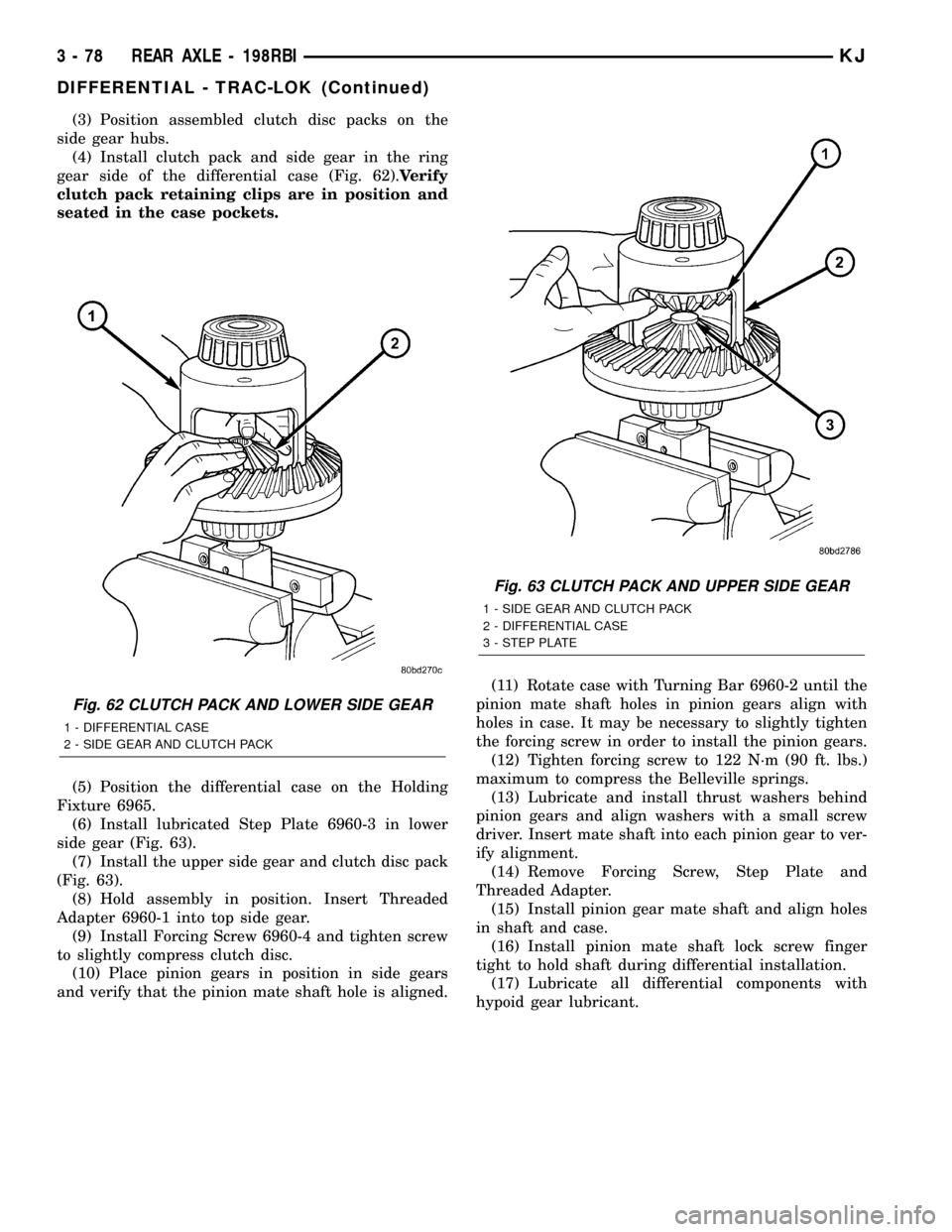
(3) Position assembled clutch disc packs on the
side gear hubs.
(4) Install clutch pack and side gear in the ring
gear side of the differential case (Fig. 62).Verify
clutch pack retaining clips are in position and
seated in the case pockets.
(5) Position the differential case on the Holding
Fixture 6965.
(6) Install lubricated Step Plate 6960-3 in lower
side gear (Fig. 63).
(7) Install the upper side gear and clutch disc pack
(Fig. 63).
(8) Hold assembly in position. Insert Threaded
Adapter 6960-1 into top side gear.
(9) Install Forcing Screw 6960-4 and tighten screw
to slightly compress clutch disc.
(10) Place pinion gears in position in side gears
and verify that the pinion mate shaft hole is aligned.(11) Rotate case with Turning Bar 6960-2 until the
pinion mate shaft holes in pinion gears align with
holes in case. It may be necessary to slightly tighten
the forcing screw in order to install the pinion gears.
(12) Tighten forcing screw to 122 N´m (90 ft. lbs.)
maximum to compress the Belleville springs.
(13) Lubricate and install thrust washers behind
pinion gears and align washers with a small screw
driver. Insert mate shaft into each pinion gear to ver-
ify alignment.
(14) Remove Forcing Screw, Step Plate and
Threaded Adapter.
(15) Install pinion gear mate shaft and align holes
in shaft and case.
(16) Install pinion mate shaft lock screw finger
tight to hold shaft during differential installation.
(17) Lubricate all differential components with
hypoid gear lubricant.
Fig. 62 CLUTCH PACK AND LOWER SIDE GEAR
1 - DIFFERENTIAL CASE
2 - SIDE GEAR AND CLUTCH PACK
Fig. 63 CLUTCH PACK AND UPPER SIDE GEAR
1 - SIDE GEAR AND CLUTCH PACK
2 - DIFFERENTIAL CASE
3 - STEP PLATE
3 - 78 REAR AXLE - 198RBIKJ
DIFFERENTIAL - TRAC-LOK (Continued)
Page 135 of 1803

REAR AXLE-81/4
TABLE OF CONTENTS
page page
REAR AXLE-81/4
DESCRIPTION.........................86
OPERATION...........................86
DIAGNOSIS AND TESTING - AXLE..........88
REMOVAL.............................91
INSTALLATION.........................91
ADJUSTMENTS........................92
SPECIFICATIONS
REAR AXLE..........................98
SPECIAL TOOLS
8 1/4 AXLE..........................98
AXLE SHAFTS
REMOVAL............................101
INSTALLATION........................101
AXLE SHAFT SEALS
REMOVAL............................101
INSTALLATION........................102
AXLE BEARINGS
REMOVAL............................102
INSTALLATION........................102PINION SEAL
REMOVAL............................102
INSTALLATION........................103
DIFFERENTIAL
REMOVAL............................104
DISASSEMBLY........................105
ASSEMBLY...........................105
INSTALLATION........................105
DIFFERENTIAL - TRAC-LOK
DIAGNOSIS AND TESTING - TRAC-LOKT....106
DISASSEMBLY........................107
CLEANING...........................109
INSPECTION.........................109
ASSEMBLY...........................109
DIFFERENTIAL CASE BEARINGS
REMOVAL............................110
INSTALLATION........................110
PINION GEAR/RING GEAR/TONE RING
REMOVAL............................110
INSTALLATION........................112
REAR AXLE-81/4
DESCRIPTION
The axle housings consist of a cast iron center sec-
tion with axle tubes extending from either side. The
tubes are pressed into and welded to the differential
housing to form a one-piece axle housing. The axles
are equipped with semi-floating axle shafts, meaning
vehicle loads are supported by the axle shaft and
bearings. The axle shafts are retained by C-locks in
the differential side gears.
The differential case is a one-piece design. The dif-
ferential pinion mate shaft is retained with a
threaded pin. Differential bearing preload and ring
gear backlash are set and maintained by threaded
adjusters at the outside of the differential housing.
Pinion bearing preload is set and maintained by the
use of a collapsible spacer.
The differential cover provides a means for inspec-
tion and service without removing the complete axlefrom the vehicle. A vent hose is used to relieve inter-
nal pressure caused by lubricant vaporization and
internal expansion.
Axles equipped with a Trac-Loktdifferential are
optional. A differential has a one-piece differential
case, and the same internal components as a stan-
dard differential, plus two clutch disc packs.
OPERATION
The axle receives power from the transmission/
transfer case through the rear propeller shaft. The
rear propeller shaft is connected to the pinion gear
which rotates the differential through the gear mesh
with the ring gear bolted to the differential case. The
engine power is transmitted to the axle shafts
through the pinion mate and side gears. The side
gears are splined to the axle shafts.
3 - 86 REAR AXLE-81/4KJ
Page 140 of 1803

REMOVAL
(1) Raise and support the vehicle.
(2) Position a lift/jack under the axle and secure
axle to device.
(3) Remove wheels and tires.
(4) Mark propeller shaft and pinion yoke for
installation reference.
(5) Remove propeller shaft and suspend under the
vehicle.
(6) Remove brake drums, parking brake cables and
speed sensor from the axle.
(7) Disconnect the brake hose at the body junction
block.
(8) Remove brakes and backing plates.
(9) Remove vent hose from the axle shaft tube.
(10) Remove the stabilizer bar (Fig. 4).
(11) Remove upper control arm ball joint pinch
bolt from bracket (Fig. 5).
(12) Remove shock absorbers from axle brackets
(Fig. 6).
(13) Loosen all lower control arms mounting bolts
(Fig. 7).
(14) Lower axle enough to remove coil springs and
spring insulators.
(15) Remove lower control arm bolts from the axle
brackets.
(16) Lower and remove the axle.
INSTALLATION
CAUTION: The weight of the vehicle must be sup-
ported by the springs before the lower control arms
are tightened. This must be done to maintain vehi-
cle ride height and prevent premature bushing fail-
ure.(1) Raise the axle under the vehicle.
(2) Install lower control arms onto the axle brack-
ets and loosely install the mounting bolts.
(3) Install coil spring isolators and spring.
(4) Raise axle up until springs are seated.
(5) Install upper control arm ball joint into axle
bracket and tighten pinch bolt to torque specification.
(6) Install shock absorbers and tighten nuts to
torque specification.
(7) Install stabilizer bar and tighten nuts to torque
specification.
(8) Install brake backing plates, parking brake
cables, brake drums and speed sensor.
(9) Install brake hose to the body junction block
and bleed the brakes.
Fig. 4 STABILIZER BAR MOUNTS
1 - STABILIZER BAR MOUNTING BOLTS
2 - LOWER SUSPENSION ARM
Fig. 5 BALL JOINT PINCH BOLT
1 - UPPER BALL JOINT
2 - PINCH BOLT
Fig. 6 SHOCK ABSORBER
1 - UPPER MOUNTING BOLT
2 - LOWER MOUNTING BOLT
KJREAR AXLE - 8 1/4 3 - 91
REAR AXLE - 8 1/4 (Continued)
Page 142 of 1803

PINION GEAR DEPTH VARIANCE
Original Pinion
Gear Depth
VarianceReplacement Pinion Gear Depth Variance
24232221 0 +1 +2 +3 +4
+4+0.008 +0.007 +0.006 +0.005 +0.004 +0.003 +0.002 +0.001 0
+3+0.007 +0.006 +0.005 +0.004 +0.003 +0.002 +0.001 020.001
+2+0.006 +0.005 +0.004 +0.003 +0.002 +0.001 020.00120.002
+1+0.005 +0.004 +0.003 +0.002 +0.001 020.00120.00220.003
0+0.004 +0.003 +0.002 +0.001 020.00120.00220.00320.004
21+0.003 +0.002 +0.001 020.00120.00220.00320.00420.005
22+0.002 +0.001 020.00120.00220.00320.00420.00520.006
23+0.001 020.00120.00220.00320.00420.00520.00620.007
24020.00120.00220.00320.00420.00520.00620.00720.008
PINION DEPTH MEASUREMENT
Measurements are taken with pinion bearing cups and
pinion bearings installed in the housing. Take measure-
ments with Pinion Gauge Set and Dial Indicator C-3339.
(1) Assemble Pinion Height Block 6739, Pinion
Block 8540 and rear pinion bearing onto Screw 6741
(Fig. 10).(2) Insert assembled height gauge components,
rear bearing, and screw into the housing through
pinion bearing cups (Fig. 11).
(3) Install front pinion bearing and Cone-Nut 6740
hand tight (Fig. 10).
(4) Place Arbor Disc 8541 on Arbor D-115-3 in posi-
tion in the housing side bearing cradles (Fig. 12).
Install differential bearing caps on Arbor Discs and
tighten cap bolts to 41 N´m (30 ft. lbs.).
NOTE: Arbor Discs 8541 has different step diame-
ters to fit other axles. Choose proper step for axle
being serviced.
(5) Assemble Dial Indicator C-3339 into Scooter
Block D-115-2 and secure set screw.
Fig. 10 Pinion Depth Gauge Tools
1 - DIAL INDICATOR
2 - ARBOR
3 - PINION HEIGHT BLOCK
4 - CONE
5 - SCREW
6 - PINION BLOCK
7 - SCOOTER BLOOK
8 - ARBOR DISC
Fig. 11 Pinion Height Block
1 - PINION BLOCK
2 - PINION HEIGHT BLOCK
KJREAR AXLE - 8 1/4 3 - 93
REAR AXLE - 8 1/4 (Continued)
Page 143 of 1803

(6) Position Scooter Block/Dial Indicator flush on
the pinion height block. Hold scooter block and zero
the dial indicator.
(7) Slowly slide the scooter block across the pinion
height block over to the arbor (Fig. 13). Move the
scooter block till the dial indicator probe crests the
arbor, then record the highest reading.
(8) Select a shim equal to the dial indicator read-
ing plus the drive pinion gear depth variance number
etched/marked on the pinion (Fig. 8). For example, if
the depth variance is ±2, add +0.002 in. to the dial
indicator reading.
BEARING PRELOAD AND GEAR BACKLASH
The following must be considered when adjusting
bearing preload and gear backlash:
²The maximum ring gear backlash variation is
0.076 mm (0.003 inch).
²Mark the gears so the same teeth are meshed
during all backlash measurements.
²Maintain the torque while adjusting the bearing
preload and ring gear backlash.
²Excessive adjuster torque will introduce a high
bearing load and cause premature bearing failure.
Insufficient adjuster torque can result in excessive
differential case free-play and ring gear noise.
²Insufficient adjuster torque will not support the
ring gear correctly and can cause excessive differen-
tial case free-play and ring gear noise.
NOTE: The differential bearing cups will not always
immediately follow the threaded adjusters as they
are moved during adjustment. To ensure accurate
bearing cup responses to the adjustments:
²Maintain the gear teeth engaged (meshed) as
marked.
²The bearings must be seated by rapidly rotat-
ing the pinion gear a half turn back and forth.
²Do this five to ten times each time the threaded
adjusters are adjusted.
(1) Adjust each threaded adjuster inward with
Wrench C-4164 until the differential bearing free-
play is eliminated (Fig. 14). Allow some ring gear
backlash, approximately 0.25 mm (0.01 in.) between
the ring and pinion gear. Seat the bearing cups with
the procedure described above.
Fig. 12 Gauge Tools In Housing
1 - ARBOR DISC
2 - PINION BLOCK
3 - ARBOR
4 - PINION HEIGHT BLOCK
Fig. 13 Pinion Gear Depth Measurement
1 - ARBOR
2 - SCOOTER BLOCK
3 - DIAL INDICATOR
Fig. 14 Threaded Adjuster
1 - AXLE TUBE
2 - BACKING PLATE
3 - ADJUSTER WRENCH
3 - 94 REAR AXLE-81/4KJ
REAR AXLE - 8 1/4 (Continued)
Page 144 of 1803

(2) Install dial indicator and position the plunger
against the drive side of a ring gear tooth (Fig. 15).
Measure the backlash at 4 positions (90 degrees
apart) around the ring gear. Locate and mark the
area of minimum backlash.
(3) Rotate the ring gear to the position of the least
backlash. Mark the gear so that all future backlash
measurements will be taken with the same gear
teeth meshed.
(4) Loosen the right-side, tighten the left-side
threaded adjuster. Obtain backlash of 0.076 to 0.102
mm (0.003 to 0.004 in.) with each adjuster tightened
to 14 N´m (10 ft. lbs.). Seat the bearing cups with the
procedure described above.
(5) Tighten the differential bearing cap bolts in a
criss-cross pattern to 95 N´m (70 ft. lbs.).
(6) Tighten the right-side threaded adjuster to 102
N´m (75 ft. lbs.). Seat the bearing cups with the pro-
cedure described above. Continue to tighten the
right-side adjuster and seat bearing cups until the
torque remains constant at 102 N´m (75 ft. lbs.)(7) Measure the ring gear backlash. The range of
backlash is 0.15 to 0.203 mm (0.006 to 0.008 in.).
(8) Continue increasing the torque at the right-
side threaded adjuster until the specified backlash is
obtained.
NOTE: The left-side threaded adjuster torque
should have approximately 102 N´m (75 ft. lbs.). If
the torque is considerably less, the complete
adjustment procedure must be repeated.
(9) Tighten the left-side threaded adjuster until
102 N´m (75 ft. lbs.) torque is indicated. Seat the
bearing rollers with the procedure described above.
Do this until the torque remains constant.
(10) Install the threaded adjuster locks and
tighten the lock screws to 10 N´m (90 in. lbs.).
After the proper backlash is achieved, perform the
Gear Contact Pattern procedure.
GEAR CONTACT PATTERN
The ring gear and pinion teeth contact patterns
will show if the pinion depth is correct in the hous-
ing. It will also show if the ring gear backlash has
been adjusted correctly. The backlash can be adjusted
within specifications to achieve desired tooth contact
patterns.
(1) Apply a thin coat of hydrated ferric oxide or
equivalent, to the drive and coast side of the ring
gear teeth.
(2) Wrap, twist and hold a shop towel around the
pinion yoke to increase the turning resistance of the
pinion. This will provide a more distinct contact pat-
tern.
(3) With a boxed end wrench on a ring gear bolt,
rotate the differential case one complete revolution in
both directions while a load is being applied from
shop towel.
The areas on the ring gear teeth with the greatest
degree of contact against the pinion teeth will squee-
gee the compound to the areas with the least amount
of contact. Note and compare patterns on the ring
gear teeth to Gear Tooth Contact Patterns chart (Fig.
16) and adjust pinion depth and gear backlash as
necessary.
Fig. 15 Ring Gear Backlash
1 - DIAL INDICATOR
2 - RING GEAR
3 - EXCITER RING
KJREAR AXLE - 8 1/4 3 - 95
REAR AXLE - 8 1/4 (Continued)
Page 146 of 1803

SIDE GEAR CLEARANCE
NOTE: When measuring side gear clearance, check
each gear independently. If it necessary to replace a
side gear, replace both gears as a matched set.
(1) Install the axle shafts, C-locks and pinion mate
shaft.
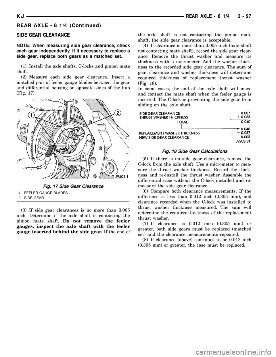
(2) Measure each side gear clearance. Insert a
matched pair of feeler gauge blades between the gear
and differential housing on opposite sides of the hub
(Fig. 17).
(3) If side gear clearances is no more than 0.005
inch. Determine if the axle shaft is contacting the
pinion mate shaft.Do not remove the feeler
gauges, inspect the axle shaft with the feeler
gauge inserted behind the side gear.If the end ofthe axle shaft is not contacting the pinion mate
shaft, the side gear clearance is acceptable.
(4) If clearance is more than 0.005 inch (axle shaft
not contacting mate shaft), record the side gear clear-
ance. Remove the thrust washer and measure its
thickness with a micrometer. Add the washer thick-
ness to the recorded side gear clearance. The sum of
gear clearance and washer thickness will determine
required thickness of replacement thrust washer
(Fig. 18).
In some cases, the end of the axle shaft will move
and contact the mate shaft when the feeler gauge is
inserted. The C-lock is preventing the side gear from
sliding on the axle shaft.
(5) If there is no side gear clearance, remove the
C-lock from the axle shaft. Use a micrometer to mea-
sure the thrust washer thickness. Record the thick-
ness and re-install the thrust washer. Assemble the
differential case without the C-lock installed and re-
measure the side gear clearance.
(6) Compare both clearance measurements. If the
difference is less than 0.012 inch (0.305 mm), add
clearance recorded when the C-lock was installed to
thrust washer thickness measured. The sum will
determine the required thickness of the replacement
thrust washer.
(7) If clearance is 0.012 inch (0.305 mm) or
greater, both side gears must be replaced (matched
set) and the clearance measurements repeated.
(8) If clearance (above) continues to be 0.012 inch
(0.305 mm) or greater, the case must be replaced.
Fig. 17 Side Gear Clearance
1 - FEELER GAUGE BLADES
2 - SIDE GEAR
Fig. 18 Side Gear Calculations
KJREAR AXLE - 8 1/4 3 - 97
REAR AXLE - 8 1/4 (Continued)
Page 149 of 1803

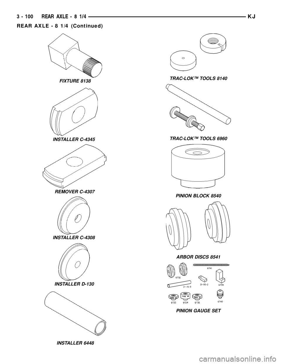
FIXTURE 8138
INSTALLER C-4345
REMOVER C-4307
INSTALLER C-4308
INSTALLER D-130
INSTALLER 6448
TRAC-LOKŸ TOOLS 8140
TRAC-LOKŸ TOOLS 6960
PINION BLOCK 8540
ARBOR DISCS 8541
PINION GAUGE SET
3 - 100 REAR AXLE-81/4KJ
REAR AXLE - 8 1/4 (Continued)