2002 JEEP LIBERTY height
[x] Cancel search: heightPage 664 of 1803

through the tube. The rack gear engages a pinion
gear that drives a gear set in the tensioner housing,
which drives the seat belt retractor spool causing the
slack to be removed from the driver side front seat
belt. Removing excess slack from the driver side front
seat belt not only keeps the occupant properly posi-
tioned for an airbag deployment following a frontal
impact of the vehicle, but also helps to reduce inju-
ries that the occupant of the driver side front seat
might experience in these situations as a result of a
harmful contact with the steering wheel and/or steer-
ing column. Also, the seat belt tensioner has a tor-
sion bar mechanism that is designed to deform in
order to control the loading being applied to the occu-
pant of the driver side front seat by the seat belt dur-
ing a frontal impact, further reducing the potential
for occupant injuries.
The ACM monitors the condition of the seat belt
tensioner through circuit resistance, and will illumi-
nate the airbag indicator in the ElectroMechanical
Instrument Cluster (EMIC) and store a Diagnostic
Trouble Code (DTC) for any fault that is detected.
For proper diagnosis of the seat belt tensioner, a
DRBIIItscan tool is required. Refer to the appropri-
ate diagnostic information.
SEAT BELT TURNING LOOP
ADJUSTER
REMOVAL
WARNING: ON VEHICLES EQUIPPED WITH AIR-
BAGS, DISABLE THE SUPPLEMENTAL RESTRAINT
SYSTEM BEFORE ATTEMPTING ANY STEERING
WHEEL, STEERING COLUMN, DRIVER AIRBAG,
PASSENGER AIRBAG, SEAT BELT TENSIONER,
FRONT IMPACT SENSORS, SIDE CURTAIN AIRBAG,
OR INSTRUMENT PANEL COMPONENT DIAGNOSIS
OR SERVICE. DISCONNECT AND ISOLATE THE
BATTERY NEGATIVE (GROUND) CABLE, THEN
WAIT TWO MINUTES FOR THE SYSTEM CAPACI-
TOR TO DISCHARGE BEFORE PERFORMING FUR-
THER DIAGNOSIS OR SERVICE. THIS IS THE ONLY
SURE WAY TO DISABLE THE SUPPLEMENTAL
RESTRAINT SYSTEM. FAILURE TO TAKE THE
PROPER PRECAUTIONS COULD RESULT IN ACCI-
DENTAL AIRBAG DEPLOYMENT AND POSSIBLE
PERSONAL INJURY.
WARNING: DURING AND FOLLOWING ANY SEAT
BELT SERVICE, CAREFULLY INSPECT ALL SEAT
BELTS, BUCKLES, MOUNTING HARDWARE, AND
RETRACTORS FOR PROPER INSTALLATION,
OPERATION, OR DAMAGE. REPLACE ANY BELTTHAT IS CUT, FRAYED, OR TORN. STRAIGHTEN
ANY BELT THAT IS TWISTED. TIGHTEN ANY
LOOSE FASTENERS. REPLACE ANY BELT THAT
HAS A DAMAGED OR INOPERATIVE BUCKLE OR
RETRACTOR. REPLACE ANY BELT THAT HAS A
BENT OR DAMAGED LATCH PLATE OR ANCHOR
PLATE. NEVER ATTEMPT TO REPAIR A SEAT BELT
COMPONENT. ALWAYS REPLACE DAMAGED OR
FAULTY SEAT BELT COMPONENTS WITH THE COR-
RECT, NEW AND UNUSED REPLACEMENT PARTS
LISTED IN THE MOPAR PARTS CATALOG.
(1) Disconnect and isolate the battery negative
cable. Wait two minutes for the system capacitor to
discharge before further service.
(2) Unsnap and lift the trim cover to access the
nut that secures the front seat belt turning loop to
the height adjuster on the upper B-pillar.
(3) Remove the nut that secures the seat belt turn-
ing loop to the height adjuster stud on the upper
B-pillar.
(4) Remove the seat belt turning loop from the
height adjuster stud.
(5) Remove the upper trim from the inside of the
B-pillar. (Refer to 23 - BODY/INTERIOR/B-PILLAR
UPPER TRIM - REMOVAL).
(6) Remove the screw that secures the seat belt
turning loop adjuster to the upper B-pillar (Fig. 35).
(7) Pull the upper end of the turning loop adjuster
away from the B-pillar far enough to disengage the
hooks on the lower end of the adjuster from the slots
in the B-pillar.
(8) Remove the seat belt turning loop adjuster
from the B-pillar.
Fig. 35 Seat Belt Turning Loop Adjuster Remove/
Install
1 - SCREW
2 - B-PILLAR
3 - ADJUSTER
KJRESTRAINTS 8O - 37
SEAT BELT TENSIONER (Continued)
Page 665 of 1803

INSTALLATION
WARNING: ON VEHICLES EQUIPPED WITH AIR-
BAGS, DISABLE THE SUPPLEMENTAL RESTRAINT
SYSTEM BEFORE ATTEMPTING ANY STEERING
WHEEL, STEERING COLUMN, DRIVER AIRBAG,
PASSENGER AIRBAG, SEAT BELT TENSIONER,
FRONT IMPACT SENSORS, SIDE CURTAIN AIRBAG,
OR INSTRUMENT PANEL COMPONENT DIAGNOSIS
OR SERVICE. DISCONNECT AND ISOLATE THE
BATTERY NEGATIVE (GROUND) CABLE, THEN
WAIT TWO MINUTES FOR THE SYSTEM CAPACI-
TOR TO DISCHARGE BEFORE PERFORMING FUR-
THER DIAGNOSIS OR SERVICE. THIS IS THE ONLY
SURE WAY TO DISABLE THE SUPPLEMENTAL
RESTRAINT SYSTEM. FAILURE TO TAKE THE
PROPER PRECAUTIONS COULD RESULT IN ACCI-
DENTAL AIRBAG DEPLOYMENT AND POSSIBLE
PERSONAL INJURY.
WARNING: DURING AND FOLLOWING ANY SEAT
BELT SERVICE, CAREFULLY INSPECT ALL SEAT
BELTS, BUCKLES, MOUNTING HARDWARE, AND
RETRACTORS FOR PROPER INSTALLATION,
OPERATION, OR DAMAGE. REPLACE ANY BELT
THAT IS CUT, FRAYED, OR TORN. STRAIGHTEN
ANY BELT THAT IS TWISTED. TIGHTEN ANY
LOOSE FASTENERS. REPLACE ANY BELT THAT
HAS A DAMAGED OR INOPERATIVE BUCKLE OR
RETRACTOR. REPLACE ANY BELT THAT HAS A
BENT OR DAMAGED LATCH PLATE OR ANCHOR
PLATE. NEVER ATTEMPT TO REPAIR A SEAT BELT
COMPONENT. ALWAYS REPLACE DAMAGED OR
FAULTY SEAT BELT COMPONENTS WITH THE COR-
RECT, NEW AND UNUSED REPLACEMENT PARTS
LISTED IN THE MOPAR PARTS CATALOG.
(1) Position the seat belt turning loop adjuster to
the B-pillar (Fig. 35).
(2) Engage the hooks on the lower end of the
adjuster into the slots in the B-pillar.
(3) Tilt the upper end of the turning loop adjuster
up into position against the B-pillar.
(4) Install and tighten the screw that secures the
seat belt turning loop adjuster to the upper B-pillar.
Tighten the screw to 34 N´m (25 ft. lbs.).
(5) Reinstall the upper trim onto the inside of the
B-pillar. (Refer to 23 - BODY/INTERIOR/B-PILLAR
UPPER TRIM - INSTALLATION).
(6) Position the seat belt turning loop onto the
height adjuster stud on the upper B-pillar.
(7) Install and tighten the nut that secures the
seat belt turning loop to the height adjuster stud.
Tighten the nut to 34 N´m (25 ft. lbs.).(8) Fold and snap the trim cover back into place to
conceal the nut that secures the front seat belt turn-
ing loop to the height adjuster on the upper B-pillar.
(9) Reconnect the battery negative cable.
SIDE CURTAIN AIRBAG
DESCRIPTION
Optional side curtain airbags are available for this
model when it is also equipped with dual front air-
bags. These airbags are passive, inflatable, Supple-
mental Restraint System (SRS) components, and
vehicles with this equipment can be readily identified
by a molded identification trim button with the ªSRS
- AIRBAGº logo located on the headliner above each
B-pillar (Fig. 36). This system is designed to reduce
injuries to the vehicle occupants in the event of a
side impact collision.
Vehicles equipped with side curtain airbags have
two individually controlled curtain airbag units.
These airbag units are concealed and mounted above
the headliner where they are each secured to one of
the roof side rails (Fig. 37). Each folded airbag cush-
ion is contained within a long extruded plastic chan-
nel that extends along the roof rail from the A-pillar
at the front of the vehicle to just behind the C-pillar
at the rear of the vehicle. The channel is secured
with plastic push-in fasteners to the roof rail. A
tether extends down the A-pillar from the front of the
airbag cushion, where it is retained to the pillar with
plastic push-in routing clips and it is secured to the
base of the A-pillar near the belt line with a screw.
The hybrid-type inflator for each airbag is secured
to the roof rail at the rear of the airbag unit between
the C-pillar and the D-pillar, and is connected to the
airbag cushion by a long tubular manifold. The
bracket holding the inflator and three other brackets
holding the manifold are secured to the roof rail with
Fig. 36 SRS Logo
8O - 38 RESTRAINTSKJ
SEAT BELT TURNING LOOP ADJUSTER (Continued)
Page 1229 of 1803
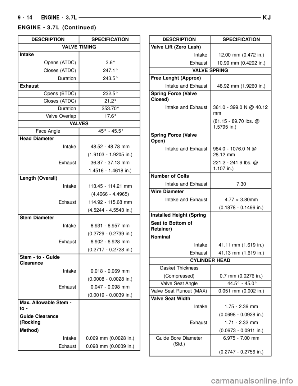
DESCRIPTION SPECIFICATION
VALVE TIMING
Intake
Opens (ATDC) 3.6É
Closes (ATDC) 247.1É
Duration 243.5É
Exhaust
Opens (BTDC) 232.5É
Closes (ATDC) 21.2É
Duration 253.70É
Valve Overlap 17.6É
VA LV E S
Face Angle 45É - 45.5É
Head Diameter
Intake 48.52 - 48.78 mm
(1.9103 - 1.9205 in.)
Exhaust 36.87 - 37.13 mm
1.4516 - 1.4618 in.)
Length (Overall)
Intake 113.45 - 114.21 mm
(4.4666 - 4.4965)
Exhaust 114.92 - 115.68 mm
(4.5244 - 4.5543 in.)
Stem Diameter
Intake 6.931 - 6.957 mm
(0.2729 - 0.2739 in.)
Exhaust 6.902 - 6.928 mm
(0.2717 - 0.2728 in.)
Stem - to - Guide
Clearance
Intake 0.018 - 0.069 mm
(0.0008 - 0.0028 in.)
Exhaust 0.047 - 0.098 mm
(0.0019 - 0.0039 in.)
Max. Allowable Stem -
to -
Guide Clearance
(Rocking
Method)
Intake 0.069 mm (0.0028 in.)
Exhaust 0.098 mm (0.0039 in.)DESCRIPTION SPECIFICATION
Valve Lift (Zero Lash)
Intake 12.00 mm (0.472 in.)
Exhaust 10.90 mm (0.4292 in.)
VALVE SPRING
Free Lenght (Approx)
Intake and Exhaust 48.92 mm (1.9260 in.)
Spring Force (Valve
Closed)
Intake and Exhaust 361.0 - 399.0 N @ 40.12
mm
(81.15 - 89.70 lbs. @
1.5795 in.)
Spring Force (Valve
Open)
Intake and Exhaust 984.0 - 1076.0 N @
28.12 mm
221.2 - 241.9 lbs. @
1.107 in.)
Number of Coils
Intake and Exhaust 7.30
Wire Diameter
Intake and Exhaust 4.77 ý 3.80mm
(0.1878 - 0.1496 in.)
Installed Height (Spring
Seat to Bottom of
Retainer)
Nominal
Intake 41.11 mm (1.619 in.)
Exhaust 41.13 mm (1.619 in.)
CYLINDER HEAD
Gasket Thickness
(Compressed) 0.7 mm (0.0276 in.)
Valve Seat Angle 44.5É - 45.0É
Valve Seat Runout (MAX) 0.051 mm (0.002 in.)
Valve Seat Width
Intake 1.75 - 2.36 mm
(0.0698 - 0.0928 in.)
Exhaust 1.71 - 2.32 mm
(0.0673 - 0.0911 in.)
Guide Bore Diameter
(Std.)6.975 - 7.00 mm
(0.2747 - 0.2756 in.)
9 - 14 ENGINE - 3.7LKJ
ENGINE - 3.7L (Continued)
Page 1242 of 1803
valve. Remove the valve and examine the valve face.
If the blue is transferred below the top edge of the
valve face, lower the valve seat using a 15 degree
stone. If the blue is transferred to the bottom edge of
the valve face, raise the valve seat using a 65 degree
stone.
(3) When the seat is properly positioned the width
of the intake seat must be 1.75 ± 2.36 mm (0.0689 ±
0.0928 in.) and the exhaust seat must be 1.71 ± 2.32
mm (0.0673 ± 0.0911 in.).
(4) Check the valve spring installed height after
refacing the valve and seat. The installed height for
both intake and exhaust valve springs must not
exceed 41.44 mm (1.6315 in.).
(5) The valve seat and valve face must maintain a
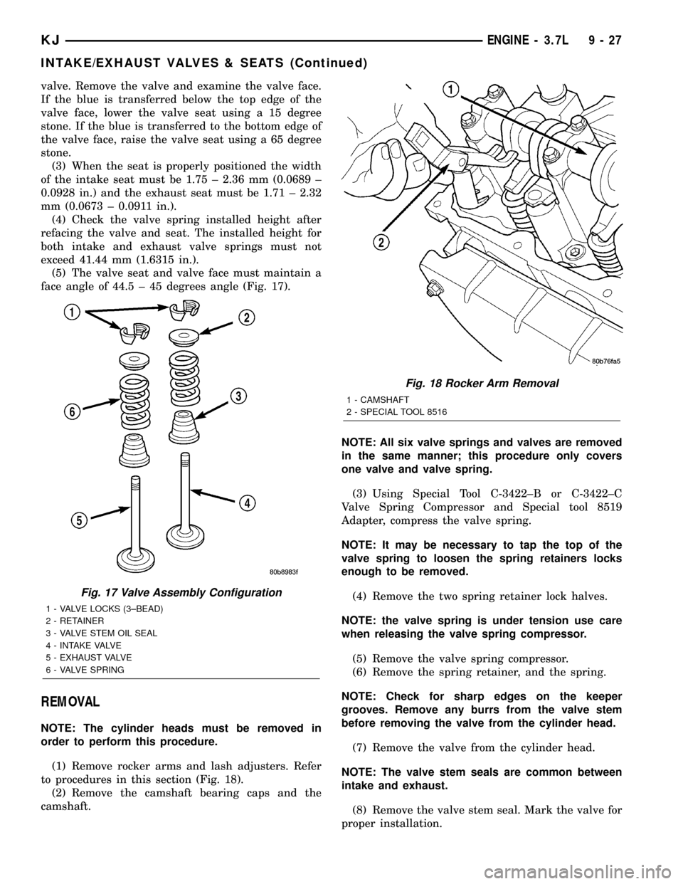
face angle of 44.5 ± 45 degrees angle (Fig. 17).
REMOVAL
NOTE: The cylinder heads must be removed in
order to perform this procedure.
(1) Remove rocker arms and lash adjusters. Refer
to procedures in this section (Fig. 18).
(2) Remove the camshaft bearing caps and the
camshaft.NOTE: All six valve springs and valves are removed
in the same manner; this procedure only covers
one valve and valve spring.
(3) Using Special Tool C-3422±B or C-3422±C
Valve Spring Compressor and Special tool 8519
Adapter, compress the valve spring.
NOTE: It may be necessary to tap the top of the
valve spring to loosen the spring retainers locks
enough to be removed.
(4) Remove the two spring retainer lock halves.
NOTE: the valve spring is under tension use care
when releasing the valve spring compressor.
(5) Remove the valve spring compressor.
(6) Remove the spring retainer, and the spring.
NOTE: Check for sharp edges on the keeper
grooves. Remove any burrs from the valve stem
before removing the valve from the cylinder head.
(7) Remove the valve from the cylinder head.
NOTE: The valve stem seals are common between
intake and exhaust.
(8) Remove the valve stem seal. Mark the valve for
proper installation.
Fig. 17 Valve Assembly Configuration
1 - VALVE LOCKS (3±BEAD)
2 - RETAINER
3 - VALVE STEM OIL SEAL
4 - INTAKE VALVE
5 - EXHAUST VALVE
6 - VALVE SPRING
Fig. 18 Rocker Arm Removal
1 - CAMSHAFT
2 - SPECIAL TOOL 8516
KJENGINE - 3.7L 9 - 27
INTAKE/EXHAUST VALVES & SEATS (Continued)
Page 1243 of 1803
TESTING VALVE SPRINGS
NOTE: Whenever the valves are removed from the
cylinder head it is recommended that the valve
springs be inspected and tested for reuse.
Inspect the valve springs for physical signs of wear
or damage. Turn table of tool C-647 until surface is
in line with the 40.69 mm (1.602 in.) mark on the
threaded stud and the zero mark on the front. Place
spring over the stud on the table and lift compress-
ing lever to set tone device. Pull on torque wrench
until Ping is heard. Take reading on torque wrench
at this instant. Multiply this reading by two. This
will give the spring load at test length. Fractional
measurements are indicated on the table for finer
adjustments. Refer to Specifications Section to obtain
specified height and allowable tensions. Replace any
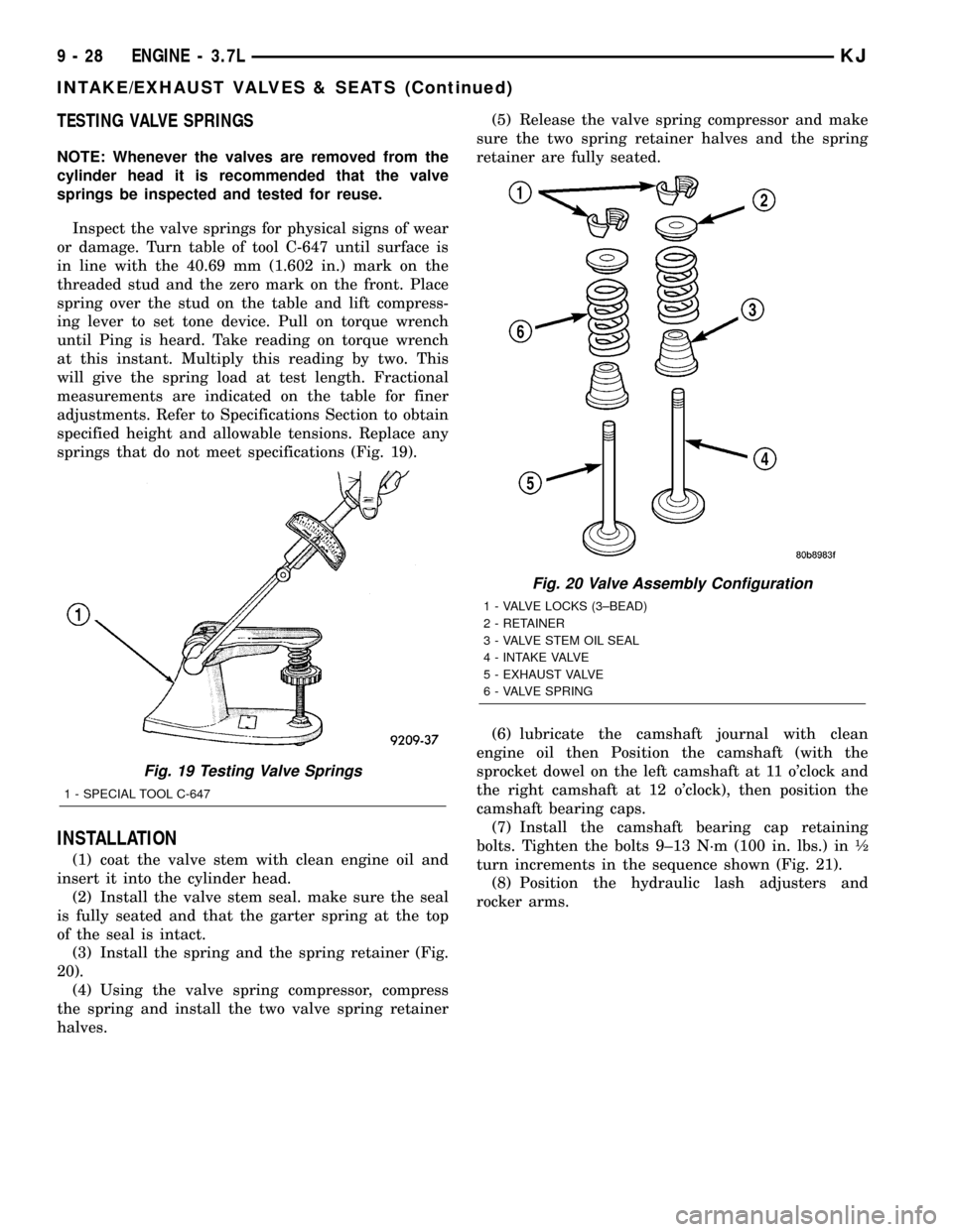
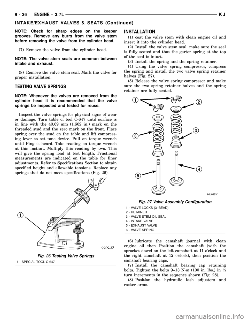
springs that do not meet specifications (Fig. 19).
INSTALLATION
(1) coat the valve stem with clean engine oil and
insert it into the cylinder head.
(2) Install the valve stem seal. make sure the seal
is fully seated and that the garter spring at the top
of the seal is intact.
(3) Install the spring and the spring retainer (Fig.
20).
(4) Using the valve spring compressor, compress
the spring and install the two valve spring retainer
halves.(5) Release the valve spring compressor and make
sure the two spring retainer halves and the spring
retainer are fully seated.
(6) lubricate the camshaft journal with clean
engine oil then Position the camshaft (with the
sprocket dowel on the left camshaft at 11 o'clock and
the right camshaft at 12 o'clock), then position the
camshaft bearing caps.
(7) Install the camshaft bearing cap retaining
bolts. Tighten the bolts 9±13 N´m (100 in. lbs.) in ó
turn increments in the sequence shown (Fig. 21).
(8) Position the hydraulic lash adjusters and
rocker arms.
Fig. 19 Testing Valve Springs
1 - SPECIAL TOOL C-647
Fig. 20 Valve Assembly Configuration
1 - VALVE LOCKS (3±BEAD)
2 - RETAINER
3 - VALVE STEM OIL SEAL
4 - INTAKE VALVE
5 - EXHAUST VALVE
6 - VALVE SPRING
9 - 28 ENGINE - 3.7LKJ
INTAKE/EXHAUST VALVES & SEATS (Continued)
Page 1250 of 1803
NOTE: When refacing valves and valve seats, it is
important that the correct size valve guide pilot be
used for reseating stones. A true and complete sur-
face must be obtained.
(1) Using a suitable dial indicator measure the
center of the valve seat Total run out must not
exceed 0.051 mm (0.002 in).
(2) Apply a small amount of Prussian blue to the
valve seat, insert the valve into the cylinder head,
while applying light pressure on the valve rotate the
valve. Remove the valve and examine the valve face.
If the blue is transferred below the top edge of the
valve face, lower the valve seat using a 15 degree
stone. If the blue is transferred to the bottom edge of
the valve face, raise the valve seat using a 65 degree
stone.
(3) When the seat is properly positioned the width
of the intake seat must be 1.75 ± 2.36 mm (0.0689 ±
0.0928 in.) and the exhaust seat must be 1.71 ± 2.32
mm (0.0673 ± 0.0911 in.).
(4) Check the valve spring installed height after
refacing the valve and seat. The installed height for
both intake and exhaust valve springs must not
exceed 41.44 mm (1.6315 in.).
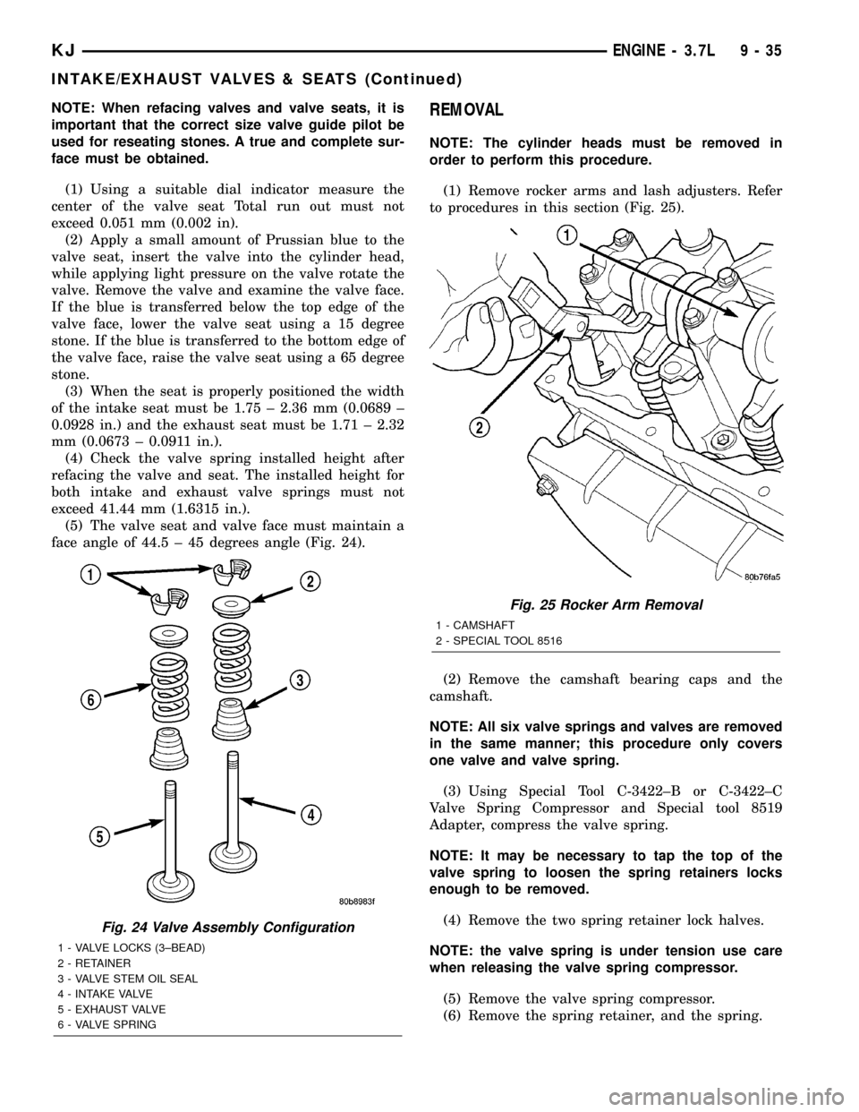
(5) The valve seat and valve face must maintain a
face angle of 44.5 ± 45 degrees angle (Fig. 24).REMOVAL
NOTE: The cylinder heads must be removed in
order to perform this procedure.
(1) Remove rocker arms and lash adjusters. Refer
to procedures in this section (Fig. 25).
(2) Remove the camshaft bearing caps and the
camshaft.
NOTE: All six valve springs and valves are removed
in the same manner; this procedure only covers
one valve and valve spring.
(3) Using Special Tool C-3422±B or C-3422±C
Valve Spring Compressor and Special tool 8519
Adapter, compress the valve spring.
NOTE: It may be necessary to tap the top of the
valve spring to loosen the spring retainers locks
enough to be removed.
(4) Remove the two spring retainer lock halves.
NOTE: the valve spring is under tension use care
when releasing the valve spring compressor.
(5) Remove the valve spring compressor.
(6) Remove the spring retainer, and the spring.
Fig. 24 Valve Assembly Configuration
1 - VALVE LOCKS (3±BEAD)
2 - RETAINER
3 - VALVE STEM OIL SEAL
4 - INTAKE VALVE
5 - EXHAUST VALVE
6 - VALVE SPRING
Fig. 25 Rocker Arm Removal
1 - CAMSHAFT
2 - SPECIAL TOOL 8516
KJENGINE - 3.7L 9 - 35
INTAKE/EXHAUST VALVES & SEATS (Continued)
Page 1251 of 1803
NOTE: Check for sharp edges on the keeper
grooves. Remove any burrs from the valve stem
before removing the valve from the cylinder head.
(7) Remove the valve from the cylinder head.
NOTE: The valve stem seals are common between
intake and exhaust.
(8) Remove the valve stem seal. Mark the valve for
proper installation.
TESTING VALVE SPRINGS
NOTE: Whenever the valves are removed from the
cylinder head it is recommended that the valve
springs be inspected and tested for reuse.
Inspect the valve springs for physical signs of wear
or damage. Turn table of tool C-647 until surface is
in line with the 40.69 mm (1.602 in.) mark on the
threaded stud and the zero mark on the front. Place
spring over the stud on the table and lift compress-
ing lever to set tone device. Pull on torque wrench
until Ping is heard. Take reading on torque wrench
at this instant. Multiply this reading by two. This
will give the spring load at test length. Fractional
measurements are indicated on the table for finer
adjustments. Refer to Specifications Section to obtain
specified height and allowable tensions. Replace any
springs that do not meet specifications (Fig. 26).
INSTALLATION
(1) coat the valve stem with clean engine oil and
insert it into the cylinder head.
(2) Install the valve stem seal. make sure the seal
is fully seated and that the garter spring at the top
of the seal is intact.
(3) Install the spring and the spring retainer.
(4) Using the valve spring compressor, compress
the spring and install the two valve spring retainer
halves (Fig. 27).
(5) Release the valve spring compressor and make
sure the two spring retainer halves and the spring
retainer are fully seated.
(6) lubricate the camshaft journal with clean
engine oil then Position the camshaft (with the
sprocket dowel on the left camshaft at 11 o'clock and
the right camshaft at 12 o'clock), then position the
camshaft bearing caps.
(7) Install the camshaft bearing cap retaining
bolts. Tighten the bolts 9±13 N´m (100 in. lbs.) in ó
turn increments in the sequence shown (Fig. 28).
(8) Position the hydraulic lash adjusters and
rocker arms.
Fig. 26 Testing Valve Springs
1 - SPECIAL TOOL C-647
Fig. 27 Valve Assembly Configuration
1 - VALVE LOCKS (3±BEAD)
2 - RETAINER
3 - VALVE STEM OIL SEAL
4 - INTAKE VALVE
5 - EXHAUST VALVE
6 - VALVE SPRING
9 - 36 ENGINE - 3.7LKJ
INTAKE/EXHAUST VALVES & SEATS (Continued)
Page 1312 of 1803
DESCRIPTION SPECIFICATION
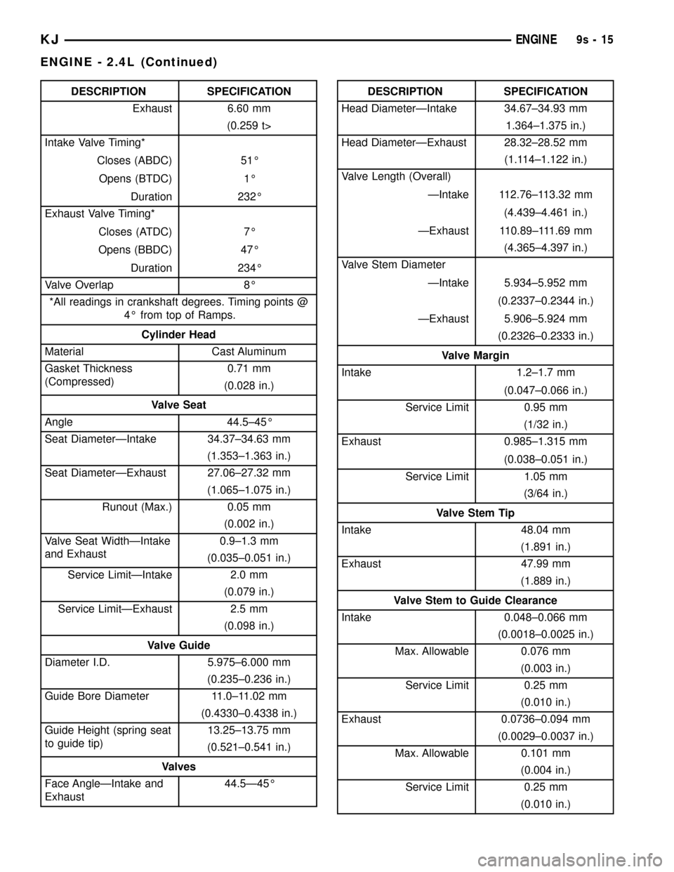
Exhaust 6.60 mm
(0.259 t>
Intake Valve Timing*
Closes (ABDC) 51É
Opens (BTDC) 1É
Duration 232É
Exhaust Valve Timing*
Closes (ATDC) 7É
Opens (BBDC) 47É
Duration 234É
Valve Overlap 8É
*All readings in crankshaft degrees. Timing points @
4É from top of Ramps.
Cylinder Head
Material Cast Aluminum
Gasket Thickness
(Compressed)0.71 mm
(0.028 in.)
Valve Seat
Angle 44.5±45É
Seat DiameterÐIntake 34.37±34.63 mm
(1.353±1.363 in.)
Seat DiameterÐExhaust 27.06±27.32 mm
(1.065±1.075 in.)
Runout (Max.) 0.05 mm
(0.002 in.)
Valve Seat WidthÐIntake
and Exhaust0.9±1.3 mm
(0.035±0.051 in.)
Service LimitÐIntake 2.0 mm
(0.079 in.)
Service LimitÐExhaust 2.5 mm
(0.098 in.)
Valve Guide
Diameter I.D. 5.975±6.000 mm
(0.235±0.236 in.)
Guide Bore Diameter 11.0±11.02 mm
(0.4330±0.4338 in.)
Guide Height (spring seat
to guide tip)13.25±13.75 mm
(0.521±0.541 in.)
Valves
Face AngleÐIntake and
Exhaust44.5Ð45ÉDESCRIPTION SPECIFICATION
Head DiameterÐIntake 34.67±34.93 mm
1.364±1.375 in.)
Head DiameterÐExhaust 28.32±28.52 mm
(1.114±1.122 in.)
Valve Length (Overall)
ÐIntake 112.76±113.32 mm
(4.439±4.461 in.)
ÐExhaust 110.89±111.69 mm
(4.365±4.397 in.)
Valve Stem Diameter
ÐIntake 5.934±5.952 mm
(0.2337±0.2344 in.)
ÐExhaust 5.906±5.924 mm
(0.2326±0.2333 in.)
Valve Margin
Intake 1.2±1.7 mm
(0.047±0.066 in.)
Service Limit 0.95 mm
(1/32 in.)
Exhaust 0.985±1.315 mm
(0.038±0.051 in.)
Service Limit 1.05 mm
(3/64 in.)
Valve Stem Tip
Intake 48.04 mm
(1.891 in.)
Exhaust 47.99 mm
(1.889 in.)
Valve Stem to Guide Clearance
Intake 0.048±0.066 mm
(0.0018±0.0025 in.)
Max. Allowable 0.076 mm
(0.003 in.)
Service Limit 0.25 mm
(0.010 in.)
Exhaust 0.0736±0.094 mm
(0.0029±0.0037 in.)
Max. Allowable 0.101 mm
(0.004 in.)
Service Limit 0.25 mm
(0.010 in.)
KJENGINE9s-15
ENGINE - 2.4L (Continued)