2002 JEEP LIBERTY spark plugs
[x] Cancel search: spark plugsPage 1307 of 1803

(1) Inspect air cleaner, induction system and
intake manifold to insure system is dry and clear of
foreign material.
(2) Remove negative battery cable.
(3) Place a shop towel around the spark plugs
when removing them from the engine. This will catch
any fluid that may possibly be in the cylinder under
pressure.
(4) With all spark plugs removed, rotate engine
crankshaft using a breaker bar and socket.
(5) Identify the fluid in the cylinder(s) (i.e., cool-
ant, fuel, oil or other).
(6) Make sure all fluid has been removed from the
cylinders. Inspect engine for damage (i.e., connecting
rods, pistons, valves, etc.)
(7) Repair engine or components as necessary to
prevent this problem from re-occurring.
CAUTION: Squirt approximately one teaspoon of oil
into the cylinders, rotate engine to lubricate the cyl-
inder walls to prevent damage on restart.
(8) Install new spark plugs.
(9) Drain engine oil and remove oil filter.
(10) Install a new oil filter.
(11) Fill engine with specified amount of approved
oil.
(12) Connect negative battery cable.
(13) Start engine and check for any leaks.
STANDARD PROCEDURE - FORM-IN-PLACE
GASKETS AND SEALERS
There are numerous places where form-in-place
gaskets are used on the engine. Care must be taken
when applying form-in-place gaskets to assure
obtaining the desired results.Do not use form-in-
place gasket material unless specified.Bead size,
continuity, and location are of great importance. Too
thin a bead can result in leakage while too much can
result in spill-over which can break off and obstruct
fluid feed lines. A continuous bead of the proper
width is essential to obtain a leak-free gasket.
There are numerous types of form-in-place gasket
materials that are used in the engine area. Mopart
Engine RTV GEN II, MopartATF-RTV, and Mopart
Gasket Maker gasket materials, each have different
properties and can not be used in place of the other.
MOPARtENGINE RTV GEN IIis used to seal
components exposed to engine oil. This material is a
specially designed black silicone rubber RTV that
retains adhesion and sealing properties when
exposed to engine oil. Moisture in the air causes the
material to cure. This material is available in three
ounce tubes and has a shelf life of one year. After one
year this material will not properly cure. Alwaysinspect the package for the expiration date before
use.
MOPARtATF RTVis a specifically designed
black silicone rubber RTV that retains adhesion and
sealing properties to seal components exposed to
automatic transmission fluid, engine coolants, and
moisture. This material is available in three ounce
tubes and has a shelf life of one year. After one year
this material will not properly cure. Always inspect
the package for the expiration date before use.
MOPARtGASKET MAKERis an anaerobic type
gasket material. The material cures in the absence of
air when squeezed between two metallic surfaces. It
will not cure if left in the uncovered tube. The
anaerobic material is for use between two machined
surfaces. Do not use on flexible metal flanges.
MOPARtBED PLATE SEALANTis a unique
(green-in-color) anaerobic type gasket material that
is specially made to seal the area between the bed-
plate and cylinder block without disturbing the bear-
ing clearance or alignment of these components. The
material cures slowly in the absence of air when
torqued between two metallic surfaces, and will rap-
idly cure when heat is applied.
MOPARtGASKET SEALANTis a slow drying,
permanently soft sealer. This material is recom-
mended for sealing threaded fittings and gaskets
against leakage of oil and coolant. Can be used on
threaded and machined parts under all tempera-
tures. This material is used on engines with multi-
layer steel (MLS) cylinder head gaskets. This
material also will prevent corrosion. MopartGasket
Sealant is available in a 13 oz. aerosol can or 4oz./16
oz. can w/applicator.
SEALER APPLICATION
MopartGasket Maker material should be applied
sparingly 1 mm (0.040 in.) diameter or less of sealant
to one gasket surface. Be certain the material sur-
rounds each mounting hole. Excess material can eas-
ily be wiped off. Components should be torqued in
place within 15 minutes. The use of a locating dowel
is recommended during assembly to prevent smear-
ing material off the location.
MopartEngine RTV GEN II or ATF RTV gasket
material should be applied in a continuous bead
approximately 3 mm (0.120 in.) in diameter. All
mounting holes must be circled. For corner sealing, a
3.17 or 6.35 mm (1/8 or 1/4 in.) drop is placed in the
center of the gasket contact area. Uncured sealant
may be removed with a shop towel. Components
should be torqued in place while the sealant is still
wet to the touch (within 10 minutes). The usage of a
locating dowel is recommended during assembly to
prevent smearing material off the location.
9s - 10 ENGINEKJ
ENGINE - 2.4L (Continued)
Page 1314 of 1803

DESCRIPTION N´mFt.
Lbs.In.
Lbs.
Oil Pump Cover
PlateÐBolts12 Ð 105
Oil Pump Pick-up
TubeÐBolt28 20 Ð
Oil Pump Relief
ValveÐCap41 30
Spark Plugs 28 Ð
Timing Belt Covers
- Front Covers to Rear
CoverÐBolts12 Ð 105
- Rear CoverÐBolts 12 Ð 105
Timing Belt Tensioner
AssemblyÐBolts61 45 Ð
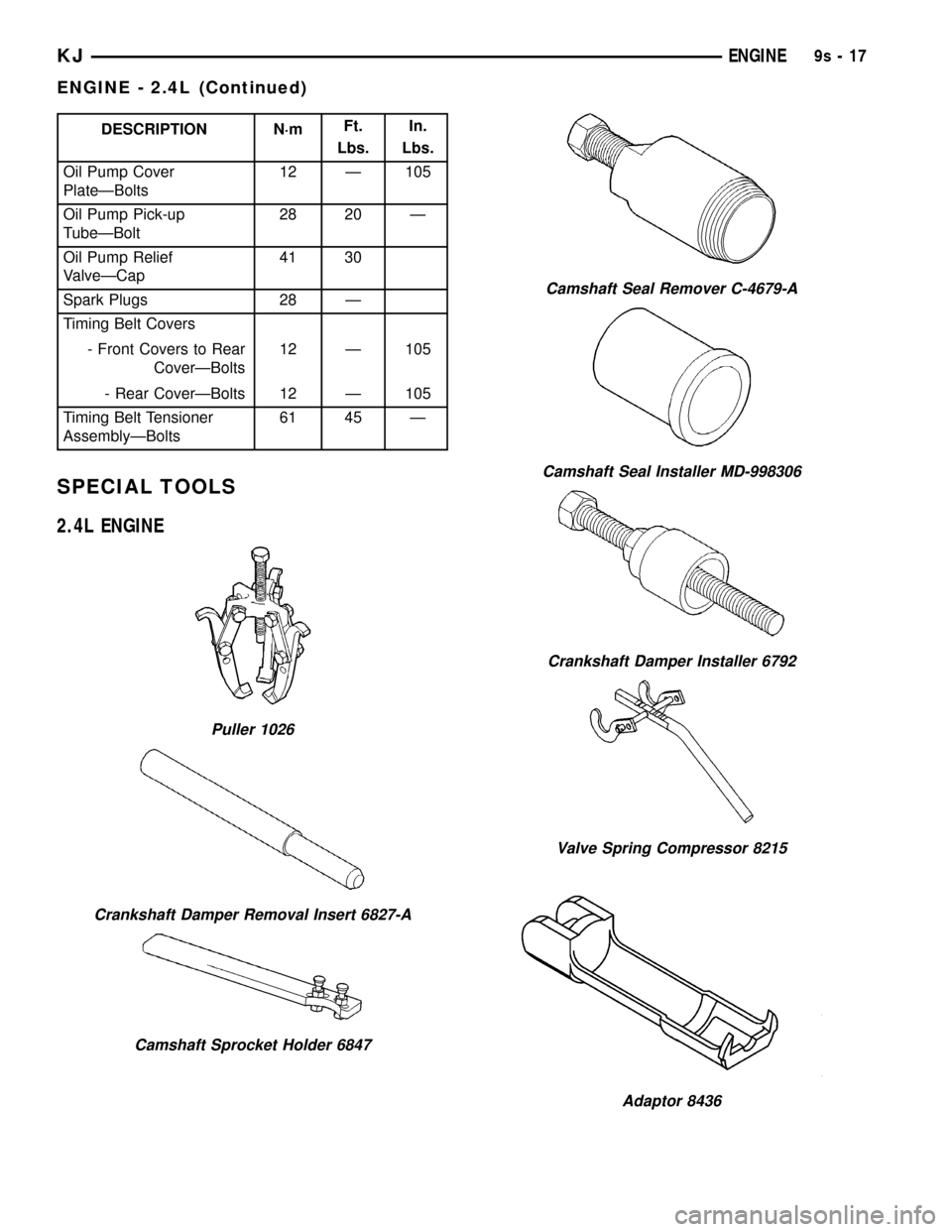
SPECIAL TOOLS
2.4L ENGINE
Puller 1026
Crankshaft Damper Removal Insert 6827-A
Camshaft Sprocket Holder 6847
Camshaft Seal Remover C-4679-A
Camshaft Seal Installer MD-998306
Crankshaft Damper Installer 6792
Valve Spring Compressor 8215
Adaptor 8436
KJENGINE9s-17
ENGINE - 2.4L (Continued)
Page 1325 of 1803

INSPECTION
(1) Whenever valves have been removed for inspec-
tion, reconditioning or replacement, valve springs
should be tested for correct tension. Discard the
springs that do not meet specifications. The following
specifications apply to both intake and exhaust
valves springs:
²Valve Closed Nominal TensionÐ76 lbs. @ 38.0
mm (1.50 in.)
²Valve Open Nominal TensionÐ136 lbs. @ 29.75
mm (1.17 in.)
(2) Inspect each valve spring for squareness with a
steel square and surface plate, test springs from both
ends. If the spring is more than 1.5 mm (1/16 inch)
out of square, install a new spring.
INSTALLATION
INSTALLATION - CYLINDER HEAD ON
(1) Install valve seal/valve spring seat assembly
(Fig. 27). Push the assembly down to seat it onto the
valve guide.
(2) Install valve spring and retainer, use Special
Tool MD-998772-A with adapter 6779 to compress
valve springs only enough to install locks. Correct
alignment of tool is necessary to avoid nicking valve
stems.
(3) Remove air hose and install spark plugs.
(4) Install camshafts and cylinder head cover .
INSTALLATION - CYLINDER HEAD OFF
(1) Coat valve stems with clean engine oil and
insert in cylinder head.(2) Install new valve stem seals on all valves
using a valve stem seal tool (Fig. 28). The valve stem
seals should be pushed firmly and squarely over
valve guide.
CAUTION: When oversize valves are used, the cor-
responding oversize valve seal must also be used.
Excessive guide wear may result if oversize seals
are not used with oversize valves.
(3) Install valve springs and retainers. Compress
valve springs only enough to install locks, taking
care not to misalign the direction of compression.
Nicked valve stems may result from misalignment of
the valve spring compressor.
CAUTION: When depressing the valve spring retain-
ers with valve spring compressor the locks can
become dislocated. Ensure both locks are in the
correct location after removing tool.
(4) Check the valve spring installed height B after
refacing the valve and seat (Fig. 29). Make sure mea-
surements are taken from top of spring seat to the
bottom surface of spring retainer. If height is greater
than 38.75 mm (1.525 in.), install a 0.762 mm (0.030
in.) spacer under the valve spring seat to bring
spring height back within specification.
HYDRAULIC LIFTERS
DIAGNOSIS AND TESTING - LASH ADJUSTER
(TAPPET) NOISE DIAGNOSIS
A tappet-like noise may be produced from several
items. Check the following items.
(1) Engine oil level too high or too low. This may
cause aerated oil to enter the adjusters and cause
them to be spongy.
Fig. 27 Valve Stem Seal/Valve Spring Seat - Typical
1 - 3-GROOVE -VALVE RETAINING LOCKS
2 - VALVE SPRING
3 - VALVE SEAL AND VALVE SPRING SEAT ASSEMBLY
4 - VALVE SPRING RETAINER
Fig. 28 Valve Stem Oil Seal Tool
1 - VALVE SEAL TOOL
2 - VALVE STEM
9s - 28 ENGINEKJ
VALVE SPRINGS (Continued)
Page 1326 of 1803

(2) Insufficient running time after rebuilding cylin-
der head. Low speed running up to 1 hour may be
required.
(3) During this time, turn engine off and let set for
a few minutes before restarting. Repeat this several
times after engine has reached normal operating
temperature.
(4) Low oil pressure.
(5) The oil restrictor (integral to the head gasket)
in the vertical oil passage to the cylinder head is
plugged with debris.
(6) Air ingested into oil due to broken or cracked
oil pump pick up.
(7) Worn valve guides.
(8) Rocker arm ears contacting valve spring
retainer.
(9) Rocker arm loose, adjuster stuck or at maxi-
mum extension and still leaves lash in the system.
(10) Faulty lash adjuster.
a. Check lash adjusters for sponginess while
installed in cylinder head. Depress part of rocker
arm over adjuster. Normal adjusters should feel very
firm. Spongy adjusters can be bottomed out easily.
b. Remove suspected lash adjusters, and replace as
necessary.
REMOVAL
NOTE: This procedure is for in-vehicle service with
camshafts installed.
(1) Remove cylinder head cover. (Refer to 9 -
ENGINE/CYLINDER HEAD/CYLINDER HEAD
COVER(S) - REMOVAL)
(2) Remove the camshafts (Refer to 9 - ENGINE/
CYLINDER HEAD/CAMSHAFT(S) - REMOVAL).
(3) Remove rocker arm. (Refer to 9 - ENGINE/
CYLINDER HEAD/ROCKER ARMS - REMOVAL)
(4) Remove hydraulic lifter (Fig. 30).(5) Repeat removal procedure for each hydraulic
lifter.
(6) If reusing, mark each hydraulic lifter for reas-
sembly in original position. Lifters are serviced as an
assembly.
INSTALLATION
(1) Install hydraulic lifter (Fig. 30). Ensure the
lifters are at least partially full of engine oil. This is
indicated by little or no plunger travel when the
lifter is depressed.
(2) Install rocker arm. (Refer to 9 - ENGINE/CYL-
INDER HEAD/ROCKER ARMS - INSTALLATION)
(3) Repeat installation procedure for each hydrau-
lic lifter.
(4) Install camshafts (Refer to 9 - ENGINE/CYL-
INDER HEAD/CAMSHAFT(S) - INSTALLATION).
(5) Install cylinder head cover. (Refer to 9 -
ENGINE/CYLINDER HEAD/CYLINDER HEAD
COVER(S) - INSTALLATION)
ROCKER ARMS
REMOVAL
NOTE: This procedure is for in-vehicle service with
camshafts installed.
(1) Remove cylinder head cover. (Refer to 9 -
ENGINE/CYLINDER HEAD/CYLINDER HEAD
COVER(S) - REMOVAL)
(2) Remove fuel rail. (Refer to 14 - FUEL SYS-
TEM/FUEL DELIVERY/FUEL RAIL - REMOVAL)
(3) Remove spark plugs.
(4) Rotate engine until the camshaft lobe, on the
follower being removed, is position on its base circle
(heel). Also, the piston should be a minimum of 6.3
mm (0.25 in) below TDC position.
Fig. 29 Checking Spring Installed Height and Valve
Tip Height Dimensions
1 - GARTER SPRING
2 - VALVE SPRING SEAT
3 - CYLINDER HEAD SURFACE
Fig. 30 Hydraulic Lash Adjuster
KJENGINE9s-29
HYDRAULIC LIFTERS (Continued)
Page 1327 of 1803

CAUTION: If cam follower assemblies are to be
reused, always mark position for reassembly in
their original positions.
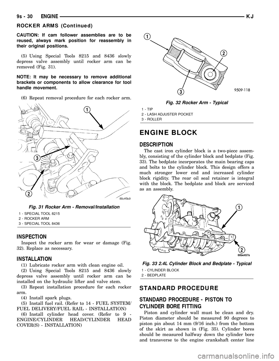
(5) Using Special Tools 8215 and 8436 slowly
depress valve assembly until rocker arm can be
removed (Fig. 31).
NOTE: It may be necessary to remove additional
brackets or components to allow clearance for tool
handle movement.
(6) Repeat removal procedure for each rocker arm.
INSPECTION
Inspect the rocker arm for wear or damage (Fig.
32). Replace as necessary.
INSTALLATION
(1) Lubricate rocker arm with clean engine oil.
(2) Using Special Tools 8215 and 8436 slowly
depress valve assembly until rocker arm can be
installed on the hydraulic lifter and valve stem.
(3) Repeat installation procedure for each rocker
arm.
(4) Install spark plugs.
(5) Install fuel rail. (Refer to 14 - FUEL SYSTEM/
FUEL DELIVERY/FUEL RAIL - INSTALLATION)
(6) Install cylinder head cover. (Refer to 9 -
ENGINE/CYLINDER HEAD/CYLINDER HEAD
COVER(S) - INSTALLATION)
ENGINE BLOCK
DESCRIPTION
The cast iron cylinder block is a two-piece assem-
bly, consisting of the cylinder block and bedplate (Fig.
33). The bedplate incorporates the main bearing caps
and bolts to the cylinder block. This design offers a
much stronger lower end and increased cylinder
block rigidity. The rear oil seal retainer is integral
with the block. The bedplate and block are serviced
as an assembly.
STANDARD PROCEDURE
STANDARD PROCEDURE - PISTON TO
CYLINDER BORE FITTING
Piston and cylinder wall must be clean and dry.
Piston diameter should be measured 90 degrees to
piston pin about 14 mm (9/16 inch.) from the bottom
of the skirt as shown in (Fig. 35). Cylinder bores
should be measured halfway down the cylinder bore
and transverse to the engine crankshaft center line
Fig. 31 Rocker Arm - Removal/Installation
1 - SPECIAL TOOL 8215
2 - ROCKER ARM
3 - SPECIAL TOOL 8436
Fig. 32 Rocker Arm - Typical
1 - TIP
2 - LASH ADJUSTER POCKET
3 - ROLLER
Fig. 33 2.4L Cylinder Block and Bedplate - Typical
1 - CYLINDER BLOCK
2 - BEDPLATE
9s - 30 ENGINEKJ
ROCKER ARMS (Continued)
Page 1363 of 1803

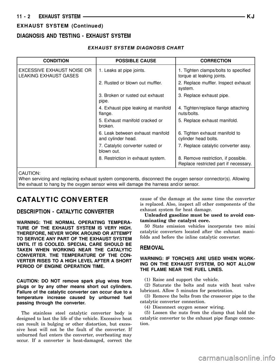
DIAGNOSIS AND TESTING - EXHAUST SYSTEM
EXHAUST SYSTEM DIAGNOSIS CHART
CONDITION POSSIBLE CAUSE CORRECTION
EXCESSIVE EXHAUST NOISE OR
LEAKING EXHAUST GASES1. Leaks at pipe joints. 1. Tighten clamps/bolts to specified
torque at leaking joints.
2. Rusted or blown out muffler. 2. Replace muffler. Inspect exhaust
system.
3. Broken or rusted out exhaust
pipe.3. Replace exhaust pipe.
4. Exhaust pipe leaking at manifold
flange.4. Tighten/replace flange attaching
nuts/bolts.
5. Exhaust manifold cracked or
broken.5. Replace exhaust manifold.
6. Leak between exhaust manifold
and cylinder head.6. Tighten exhaust manifold to
cylinder head bolts.
7. Catalytic converter rusted or
blown out.7. Replace catalytic converter assy.
8. Restriction in exhaust system. 8. Remove restriction, if possible.
Replace restricted part if necessary.
CAUTION:
When servicing and replacing exhaust system components, disconnect the oxygen sensor connector(s). Allowing
the exhaust to hang by the oxygen sensor wires will damage the harness and/or sensor.
CATALYTIC CONVERTER
DESCRIPTION - CATALYTIC CONVERTER
WARNING: THE NORMAL OPERATING TEMPERA-
TURE OF THE EXHAUST SYSTEM IS VERY HIGH.
THEREFORE, NEVER WORK AROUND OR ATTEMPT
TO SERVICE ANY PART OF THE EXHAUST SYSTEM
UNTIL IT IS COOLED. SPECIAL CARE SHOULD BE
TAKEN WHEN WORKING NEAR THE CATALYTIC
CONVERTER. THE TEMPERATURE OF THE CON-
VERTER RISES TO A HIGH LEVEL AFTER A SHORT
PERIOD OF ENGINE OPERATION TIME.
CAUTION: DO NOT remove spark plug wires from
plugs or by any other means short out cylinders.
Failure of the catalytic converter can occur due to a
temperature increase caused by unburned fuel
passing through the converter.
The stainless steel catalytic converter body is
designed to last the life of the vehicle. Excessive heat
can result in bulging or other distortion, but exces-
sive heat will not be the fault of the converter. If
unburned fuel enters the converter, overheating may
occur. If a converter is heat-damaged, correct thecause of the damage at the same time the converter
is replaced. Also, inspect all other components of the
exhaust system for heat damage.
Unleaded gasoline must be used to avoid con-
taminating the catalyst core.
50 State emission vehicles incorporate two mini
catalytic converters located after the exhaust mani-
folds and before the inline catalytic converter.
REMOVAL
WARNING: IF TORCHES ARE USED WHEN WORK-
ING ON THE EXHAUST SYSTEM, DO NOT ALLOW
THE FLAME NEAR THE FUEL LINES.
(1) Raise and support the vehicle.
(2) Saturate the bolts and nuts with heat valve
lubricant. Allow 5 minutes for penetration.
(3) Remove the bolts from the crossover pipe to the
catalytic converter connection.
(4) Disconnect oxygen sensor wiring.
(5) Loosen the nuts from the clamp that hold the
catalytic converter to the exhaust pipe flange connec-
tion.
11 - 2 EXHAUST SYSTEMKJ
EXHAUST SYSTEM (Continued)
Page 1369 of 1803

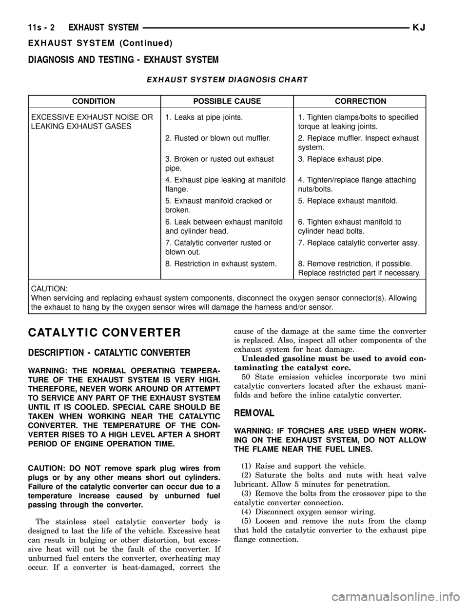
DIAGNOSIS AND TESTING - EXHAUST SYSTEM
EXHAUST SYSTEM DIAGNOSIS CHART
CONDITION POSSIBLE CAUSE CORRECTION
EXCESSIVE EXHAUST NOISE OR
LEAKING EXHAUST GASES1. Leaks at pipe joints. 1. Tighten clamps/bolts to specified
torque at leaking joints.
2. Rusted or blown out muffler. 2. Replace muffler. Inspect exhaust
system.
3. Broken or rusted out exhaust
pipe.3. Replace exhaust pipe.
4. Exhaust pipe leaking at manifold
flange.4. Tighten/replace flange attaching
nuts/bolts.
5. Exhaust manifold cracked or
broken.5. Replace exhaust manifold.
6. Leak between exhaust manifold
and cylinder head.6. Tighten exhaust manifold to
cylinder head bolts.
7. Catalytic converter rusted or
blown out.7. Replace catalytic converter assy.
8. Restriction in exhaust system. 8. Remove restriction, if possible.
Replace restricted part if necessary.
CAUTION:
When servicing and replacing exhaust system components, disconnect the oxygen sensor connector(s). Allowing
the exhaust to hang by the oxygen sensor wires will damage the harness and/or sensor.
CATALYTIC CONVERTER
DESCRIPTION - CATALYTIC CONVERTER
WARNING: THE NORMAL OPERATING TEMPERA-
TURE OF THE EXHAUST SYSTEM IS VERY HIGH.
THEREFORE, NEVER WORK AROUND OR ATTEMPT
TO SERVICE ANY PART OF THE EXHAUST SYSTEM
UNTIL IT IS COOLED. SPECIAL CARE SHOULD BE
TAKEN WHEN WORKING NEAR THE CATALYTIC
CONVERTER. THE TEMPERATURE OF THE CON-
VERTER RISES TO A HIGH LEVEL AFTER A SHORT
PERIOD OF ENGINE OPERATION TIME.
CAUTION: DO NOT remove spark plug wires from
plugs or by any other means short out cylinders.
Failure of the catalytic converter can occur due to a
temperature increase caused by unburned fuel
passing through the converter.
The stainless steel catalytic converter body is
designed to last the life of the vehicle. Excessive heat
can result in bulging or other distortion, but exces-
sive heat will not be the fault of the converter. If
unburned fuel enters the converter, overheating may
occur. If a converter is heat-damaged, correct thecause of the damage at the same time the converter
is replaced. Also, inspect all other components of the
exhaust system for heat damage.
Unleaded gasoline must be used to avoid con-
taminating the catalyst core.
50 State emission vehicles incorporate two mini
catalytic converters located after the exhaust mani-
folds and before the inline catalytic converter.
REMOVAL
WARNING: IF TORCHES ARE USED WHEN WORK-
ING ON THE EXHAUST SYSTEM, DO NOT ALLOW
THE FLAME NEAR THE FUEL LINES.
(1) Raise and support the vehicle.
(2) Saturate the bolts and nuts with heat valve
lubricant. Allow 5 minutes for penetration.
(3) Remove the bolts from the crossover pipe to the
catalytic converter connection.
(4) Disconnect oxygen sensor wiring.
(5) Loosen and remove the nuts from the clamp
that hold the catalytic converter to the exhaust pipe
flange connection.
11s - 2 EXHAUST SYSTEMKJ
EXHAUST SYSTEM (Continued)
Page 1726 of 1803

an associated limp in will take two trips to illumi-
nate the MIL.
Refer to the Diagnostic Trouble Codes Description
Charts in this section and the appropriate Power-
train Diagnostic Procedure Manual for diagnostic
procedures.
DESCRIPTION - NON-MONITORED CIRCUITS
The PCM does not monitor the following circuits,
systems and conditions that could have malfunctions
causing driveability problems. The PCM might not
store diagnostic trouble codes for these conditions.
However, problems with these systems may cause the
PCM to store diagnostic trouble codes for other sys-
tems or components. For example, a fuel pressure
problem will not register a fault directly, but could
cause a rich/lean condition or misfire. This could
cause the PCM to store an oxygen sensor or misfire
diagnostic trouble code
FUEL PRESSURE
The fuel pressure regulator controls fuel system
pressure. The PCM cannot detect a clogged fuel
pump inlet filter, clogged in-line fuel filter, or a
pinched fuel supply or return line. However, these
could result in a rich or lean condition causing the
PCM to store an oxygen sensor or fuel system diag-
nostic trouble code.
SECONDARY IGNITION CIRCUIT
The PCM cannot detect an inoperative ignition coil,
fouled or worn spark plugs, ignition cross firing, or
open spark plug cables.
CYLINDER COMPRESSION
The PCM cannot detect uneven, low, or high engine
cylinder compression.
EXHAUST SYSTEM
The PCM cannot detect a plugged, restricted or
leaking exhaust system, although it may set a fuel
system fault.
FUEL INJECTOR MECHANICAL MALFUNCTIONS
The PCM cannot determine if a fuel injector is
clogged, the needle is sticking or if the wrong injectoris installed. However, these could result in a rich or
lean condition causing the PCM to store a diagnostic
trouble code for either misfire, an oxygen sensor, or
the fuel system.
EXCESSIVE OIL CONSUMPTION
Although the PCM monitors engine exhaust oxygen
content when the system is in closed loop, it cannot
determine excessive oil consumption.
THROTTLE BODY AIRFLOW
The PCM cannot detect a clogged or restricted air
cleaner inlet or filter element.
VACUUM ASSIST
The PCM cannot detect leaks or restrictions in the
vacuum circuits of vacuum assisted engine control
system devices. However, these could cause the PCM
to store a MAP sensor diagnostic trouble code and
cause a high idle condition.
PCM SYSTEM GROUND
The PCM cannot determine a poor system ground.
However, one or more diagnostic trouble codes may
be generated as a result of this condition. The mod-
ule should be mounted to the body at all times, also
during diagnostic.
PCM CONNECTOR ENGAGEMENT
The PCM may not be able to determine spread or
damaged connector pins. However, it might store
diagnostic trouble codes as a result of spread connec-
tor pins.
DESCRIPTION - HIGH AND LOW LIMITS
The PCM compares input signal voltages from each
input device with established high and low limits for
the device. If the input voltage is not within limits
and other criteria are met, the PCM stores a diagnos-
tic trouble code in memory. Other diagnostic trouble
code criteria might include engine RPM limits or
input voltages from other sensors or switches that
must be present before verifying a diagnostic trouble
code condition.
DESCRIPTION - LOAD VALUE
ENGINE IDLE/NEUTRAL 2500 RPM/NEUTRAL
All Engines 2% to 8% of Maximum Load 9% to 17% of Maximum Load
25 - 20 EMISSIONS CONTROLKJ
EMISSIONS CONTROL (Continued)