2002 JEEP LIBERTY fuel tank removal
[x] Cancel search: fuel tank removalPage 1406 of 1803
(14) If fuel injectors are to be removed, refer to
Fuel Injector Removal/Installation.
INSTALLATION
2.4L Engine
(1) If fuel injectors are to be installed, refer to Fuel
Injector Removal/Installation.
(2) Clean out fuel injector machined bores in
intake manifold.
(3) Apply a small amount of engine oil to each fuel
injector o-ring. This will help in fuel rail installation.
(4) Position fuel rail/fuel injector assembly to
machined injector openings in intake manifold.
(5) Guide each injector into cylinder head. Be care-
ful not to tear injector o-rings.
(6) Push fuel rail down until fuel injectors have
bottomed on shoulders.
(7) Install 2 fuel rail mounting bolts and tighten.
Refer to torque specifications.
(8) Connect electrical connectors at all fuel injec-
tors. To install connector, refer to (Fig. 37). Push con-
nector onto injector (1) and then push and lock red
colored slider (2). Verify connector is locked to injec-
tor by lightly tugging on connector.
(9) Snap 2 injection wiring harness clips (Fig. 35)
into brackets.
(10) Connect 2 main engine harness connectors at
rear of intake manifold (Fig. 34).
(11) Tighten 5 intake manifold mounting bolts.
Refer to Engine Torque Specifications.
(12) Install PCV valve and hose.
(13) Install thermostat and radiator hose. Fill with
coolant. Refer to Cooling.
(14) Connect necessary vacuum lines to throttle
body.
(15) Connect fuel line latch clip and fuel line to
fuel rail. Refer to Quick-Connect Fittings.
(16) Install air duct to throttle body.
(17) Connect battery cable to battery.
(18) Start engine and check for leaks.
3.7L Engine
(1) If fuel injectors are to be installed, refer to Fuel
Injector Removal/Installation.
(2) Clean out fuel injector machined bores in
intake manifold.
(3) Apply a small amount of engine oil to each fuel
injector o-ring. This will help in fuel rail installation.
(4) Position fuel rail/fuel injector assembly to
machined injector openings in cylinder head.
(5) Guide each injector into cylinder head. Be care-
ful not to tear injector o-rings.
(6) Pushrightside of fuel rail down until fuel
injectors have bottomed on cylinder head shoulder.Pushleftfuel rail down until injectors have bot-
tomed on cylinder head shoulder.
(7) Install 4 fuel rail mounting bolts and tighten.
Refer to torque specifications.
(8) Install 6 ignition coils. Refer to Ignition Coil
Removal/Installation.
(9) Connect electrical connectors to throttle body.
(10) Connect electrical connectors at all fuel injec-
tors. To install connector, refer to (Fig. 37). Push con-
nector onto injector (1) and then push and lock red
colored slider (2). Verify connector is locked to injec-
tor by lightly tugging on connector.
(11) Connect necessary vacuum lines to throttle
body.
(12) Connect fuel line latch clip and fuel line to
fuel rail. Refer to Quick-Connect Fittings.
(13) Install air box to throttle body.
(14) Install air duct to air box.
(15) Connect battery cable to battery.
(16) Start engine and check for leaks.
FUEL TANK
DESCRIPTION
The fuel tank is constructed of a plastic material.
Its main functions are for fuel storage and for place-
ment of the fuel pump module, and certain ORVR
components.
OPERATION
All models pass a full 360 degree rollover test
without fuel leakage. To accomplish this, fuel and
vapor flow controls are required for all fuel tank con-
nections.
A check (control) valve is mounted into the top sec-
tion of the 2±piece fuel pump module. Refer to Fuel
Tank Check Valve for additional information.
An evaporation control system is connected to the
fuel tank to reduce emissions of fuel vapors into the
atmosphere. When fuel evaporates from the fuel
tank, vapors pass through vent hoses or tubes to a
charcoal canister where they are temporarily held.
When the engine is running, the vapors are drawn
into the intake manifold. Certain models are also
equipped with a self-diagnosing system using a Leak
Detection Pump (LDP) and/or an ORVR system.
Refer to Emission Control System for additional
information.
14 - 24 FUEL DELIVERYKJ
FUEL RAIL (Continued)
Page 1407 of 1803
REMOVAL
Fuel Tank Draining
WARNING: THE FUEL SYSTEM MAY BE UNDER
CONSTANT FUEL PRESSURE EVEN WITH THE
ENGINE OFF. THIS PRESSURE MUST BE
RELEASED BEFORE SERVICING FUEL TANK.
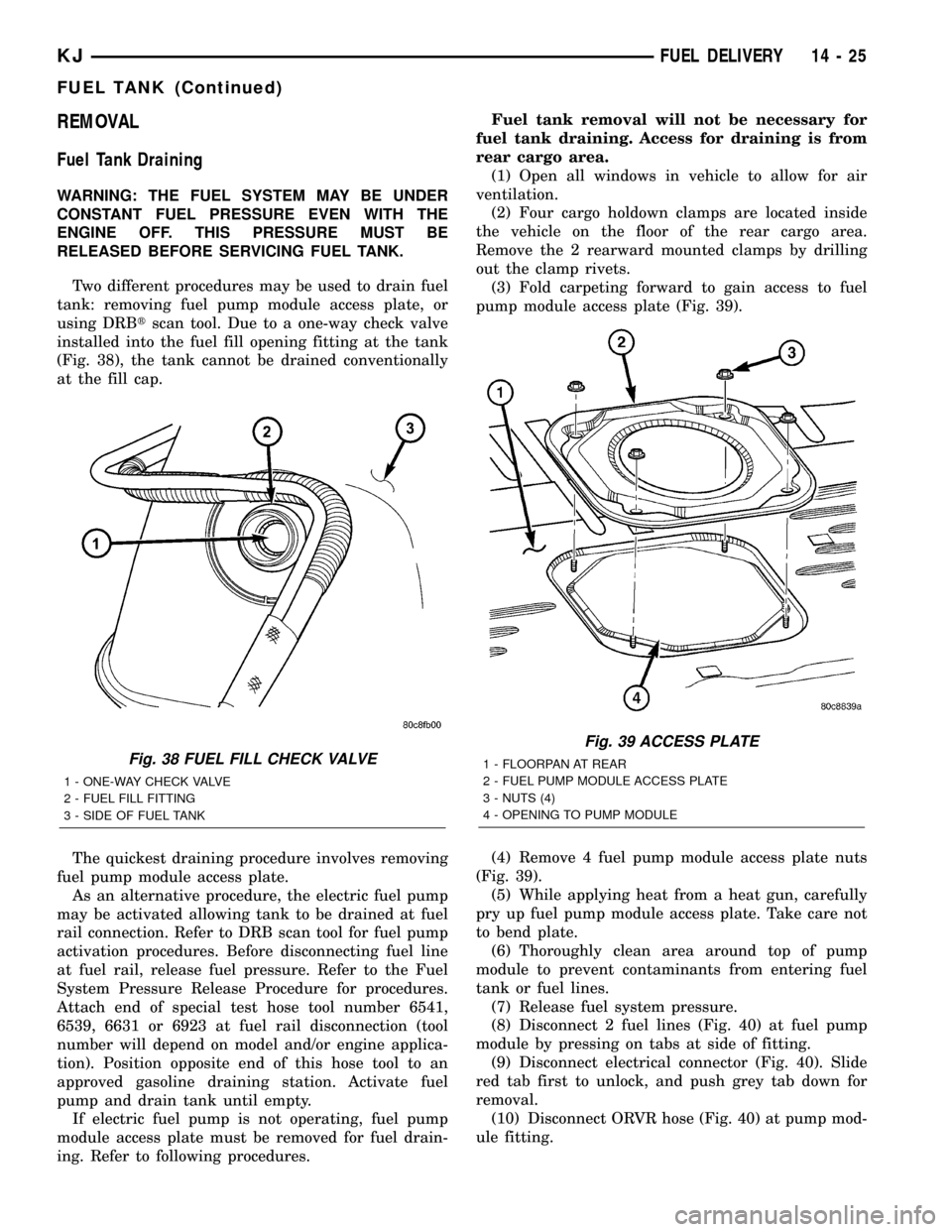
Two different procedures may be used to drain fuel
tank: removing fuel pump module access plate, or
using DRBtscan tool. Due to a one-way check valve
installed into the fuel fill opening fitting at the tank
(Fig. 38), the tank cannot be drained conventionally
at the fill cap.
The quickest draining procedure involves removing
fuel pump module access plate.
As an alternative procedure, the electric fuel pump
may be activated allowing tank to be drained at fuel
rail connection. Refer to DRB scan tool for fuel pump
activation procedures. Before disconnecting fuel line
at fuel rail, release fuel pressure. Refer to the Fuel
System Pressure Release Procedure for procedures.
Attach end of special test hose tool number 6541,
6539, 6631 or 6923 at fuel rail disconnection (tool
number will depend on model and/or engine applica-
tion). Position opposite end of this hose tool to an
approved gasoline draining station. Activate fuel
pump and drain tank until empty.
If electric fuel pump is not operating, fuel pump
module access plate must be removed for fuel drain-
ing. Refer to following procedures.Fuel tank removal will not be necessary for
fuel tank draining. Access for draining is from
rear cargo area.
(1) Open all windows in vehicle to allow for air
ventilation.
(2) Four cargo holdown clamps are located inside
the vehicle on the floor of the rear cargo area.
Remove the 2 rearward mounted clamps by drilling
out the clamp rivets.
(3) Fold carpeting forward to gain access to fuel
pump module access plate (Fig. 39).
(4) Remove 4 fuel pump module access plate nuts
(Fig. 39).
(5) While applying heat from a heat gun, carefully
pry up fuel pump module access plate. Take care not
to bend plate.
(6) Thoroughly clean area around top of pump
module to prevent contaminants from entering fuel
tank or fuel lines.
(7) Release fuel system pressure.
(8) Disconnect 2 fuel lines (Fig. 40) at fuel pump
module by pressing on tabs at side of fitting.
(9) Disconnect electrical connector (Fig. 40). Slide
red tab first to unlock, and push grey tab down for
removal.
(10) Disconnect ORVR hose (Fig. 40) at pump mod-
ule fitting.
Fig. 38 FUEL FILL CHECK VALVE
1 - ONE-WAY CHECK VALVE
2 - FUEL FILL FITTING
3 - SIDE OF FUEL TANK
Fig. 39 ACCESS PLATE
1 - FLOORPAN AT REAR
2 - FUEL PUMP MODULE ACCESS PLATE
3 - NUTS (4)
4 - OPENING TO PUMP MODULE
KJFUEL DELIVERY 14 - 25
FUEL TANK (Continued)
Page 1408 of 1803
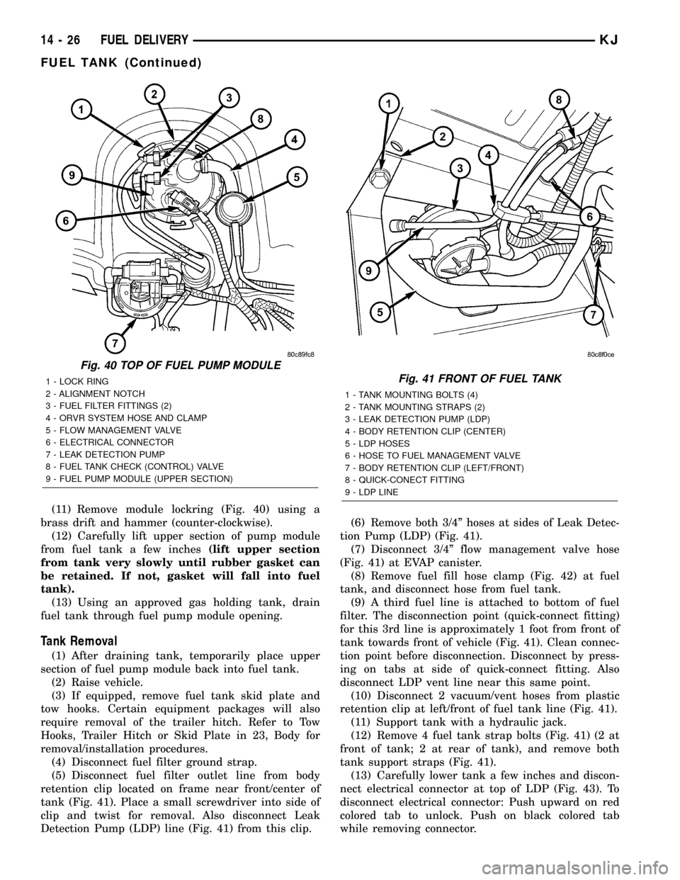
(11) Remove module lockring (Fig. 40) using a
brass drift and hammer (counter-clockwise).
(12) Carefully lift upper section of pump module
from fuel tank a few inches(lift upper section
from tank very slowly until rubber gasket can
be retained. If not, gasket will fall into fuel
tank).
(13) Using an approved gas holding tank, drain
fuel tank through fuel pump module opening.
Tank Removal
(1) After draining tank, temporarily place upper
section of fuel pump module back into fuel tank.
(2) Raise vehicle.
(3) If equipped, remove fuel tank skid plate and
tow hooks. Certain equipment packages will also
require removal of the trailer hitch. Refer to Tow
Hooks, Trailer Hitch or Skid Plate in 23, Body for
removal/installation procedures.
(4) Disconnect fuel filter ground strap.
(5) Disconnect fuel filter outlet line from body
retention clip located on frame near front/center of
tank (Fig. 41). Place a small screwdriver into side of
clip and twist for removal. Also disconnect Leak
Detection Pump (LDP) line (Fig. 41) from this clip.(6) Remove both 3/4º hoses at sides of Leak Detec-
tion Pump (LDP) (Fig. 41).
(7) Disconnect 3/4º flow management valve hose
(Fig. 41) at EVAP canister.
(8) Remove fuel fill hose clamp (Fig. 42) at fuel
tank, and disconnect hose from fuel tank.
(9) A third fuel line is attached to bottom of fuel
filter. The disconnection point (quick-connect fitting)
for this 3rd line is approximately 1 foot from front of
tank towards front of vehicle (Fig. 41). Clean connec-
tion point before disconnection. Disconnect by press-
ing on tabs at side of quick-connect fitting. Also
disconnect LDP vent line near this same point.
(10) Disconnect 2 vacuum/vent hoses from plastic
retention clip at left/front of fuel tank line (Fig. 41).
(11) Support tank with a hydraulic jack.
(12) Remove 4 fuel tank strap bolts (Fig. 41) (2 at
front of tank; 2 at rear of tank), and remove both
tank support straps (Fig. 41).
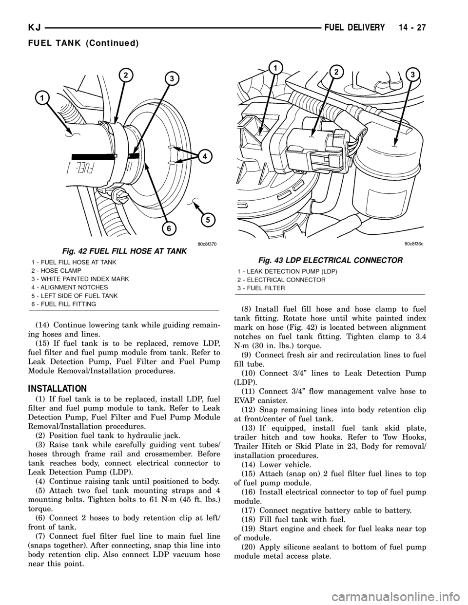
(13) Carefully lower tank a few inches and discon-
nect electrical connector at top of LDP (Fig. 43). To
disconnect electrical connector: Push upward on red
colored tab to unlock. Push on black colored tab
while removing connector.
Fig. 40 TOP OF FUEL PUMP MODULE
1 - LOCK RING
2 - ALIGNMENT NOTCH
3 - FUEL FILTER FITTINGS (2)
4 - ORVR SYSTEM HOSE AND CLAMP
5 - FLOW MANAGEMENT VALVE
6 - ELECTRICAL CONNECTOR
7 - LEAK DETECTION PUMP
8 - FUEL TANK CHECK (CONTROL) VALVE
9 - FUEL PUMP MODULE (UPPER SECTION)Fig. 41 FRONT OF FUEL TANK
1 - TANK MOUNTING BOLTS (4)
2 - TANK MOUNTING STRAPS (2)
3 - LEAK DETECTION PUMP (LDP)
4 - BODY RETENTION CLIP (CENTER)
5 - LDP HOSES
6 - HOSE TO FUEL MANAGEMENT VALVE
7 - BODY RETENTION CLIP (LEFT/FRONT)
8 - QUICK-CONECT FITTING
9 - LDP LINE
14 - 26 FUEL DELIVERYKJ
FUEL TANK (Continued)
Page 1409 of 1803
(14) Continue lowering tank while guiding remain-
ing hoses and lines.
(15) If fuel tank is to be replaced, remove LDP,
fuel filter and fuel pump module from tank. Refer to
Leak Detection Pump, Fuel Filter and Fuel Pump
Module Removal/Installation procedures.
INSTALLATION
(1) If fuel tank is to be replaced, install LDP, fuel
filter and fuel pump module to tank. Refer to Leak
Detection Pump, Fuel Filter and Fuel Pump Module
Removal/Installation procedures.
(2) Position fuel tank to hydraulic jack.
(3) Raise tank while carefully guiding vent tubes/
hoses through frame rail and crossmember. Before
tank reaches body, connect electrical connector to
Leak Detection Pump (LDP).
(4) Continue raising tank until positioned to body.
(5) Attach two fuel tank mounting straps and 4
mounting bolts. Tighten bolts to 61 N´m (45 ft. lbs.)
torque.
(6) Connect 2 hoses to body retention clip at left/
front of tank.
(7) Connect fuel filter fuel line to main fuel line
(snaps together). After connecting, snap this line into
body retention clip. Also connect LDP vacuum hose
near this point.(8) Install fuel fill hose and hose clamp to fuel
tank fitting. Rotate hose until white painted index
mark on hose (Fig. 42) is located between alignment
notches on fuel tank fitting. Tighten clamp to 3.4
N´m (30 in. lbs.) torque.
(9) Connect fresh air and recirculation lines to fuel
fill tube.
(10) Connect 3/4º lines to Leak Detection Pump
(LDP).
(11) Connect 3/4º flow management valve hose to
EVAP canister.
(12) Snap remaining lines into body retention clip
at front/center of fuel tank.
(13) If equipped, install fuel tank skid plate,
trailer hitch and tow hooks. Refer to Tow Hooks,
Trailer Hitch or Skid Plate in 23, Body for removal/
installation procedures.
(14) Lower vehicle.
(15) Attach (snap on) 2 fuel filter fuel lines to top
of fuel pump module.
(16) Install electrical connector to top of fuel pump
module.
(17) Connect negative battery cable to battery.
(18) Fill fuel tank with fuel.
(19) Start engine and check for fuel leaks near top
of module.
(20) Apply silicone sealant to bottom of fuel pump
module metal access plate.
Fig. 42 FUEL FILL HOSE AT TANK
1 - FUEL FILL HOSE AT TANK
2 - HOSE CLAMP
3 - WHITE PAINTED INDEX MARK
4 - ALIGNMENT NOTCHES
5 - LEFT SIDE OF FUEL TANK
6 - FUEL FILL FITTINGFig. 43 LDP ELECTRICAL CONNECTOR
1 - LEAK DETECTION PUMP (LDP)
2 - ELECTRICAL CONNECTOR
3 - FUEL FILTER
KJFUEL DELIVERY 14 - 27
FUEL TANK (Continued)
Page 1410 of 1803
(21) Install fuel pump module metal access plate
and 4 nuts. Tighten nuts to 3 N´m (26 in. lbs.)
torque.
(22) Position carpet and install 2 new cargo clamp
rivets into each cargo holdown clamp.
FUEL TANK CHECK VALVE
DESCRIPTION
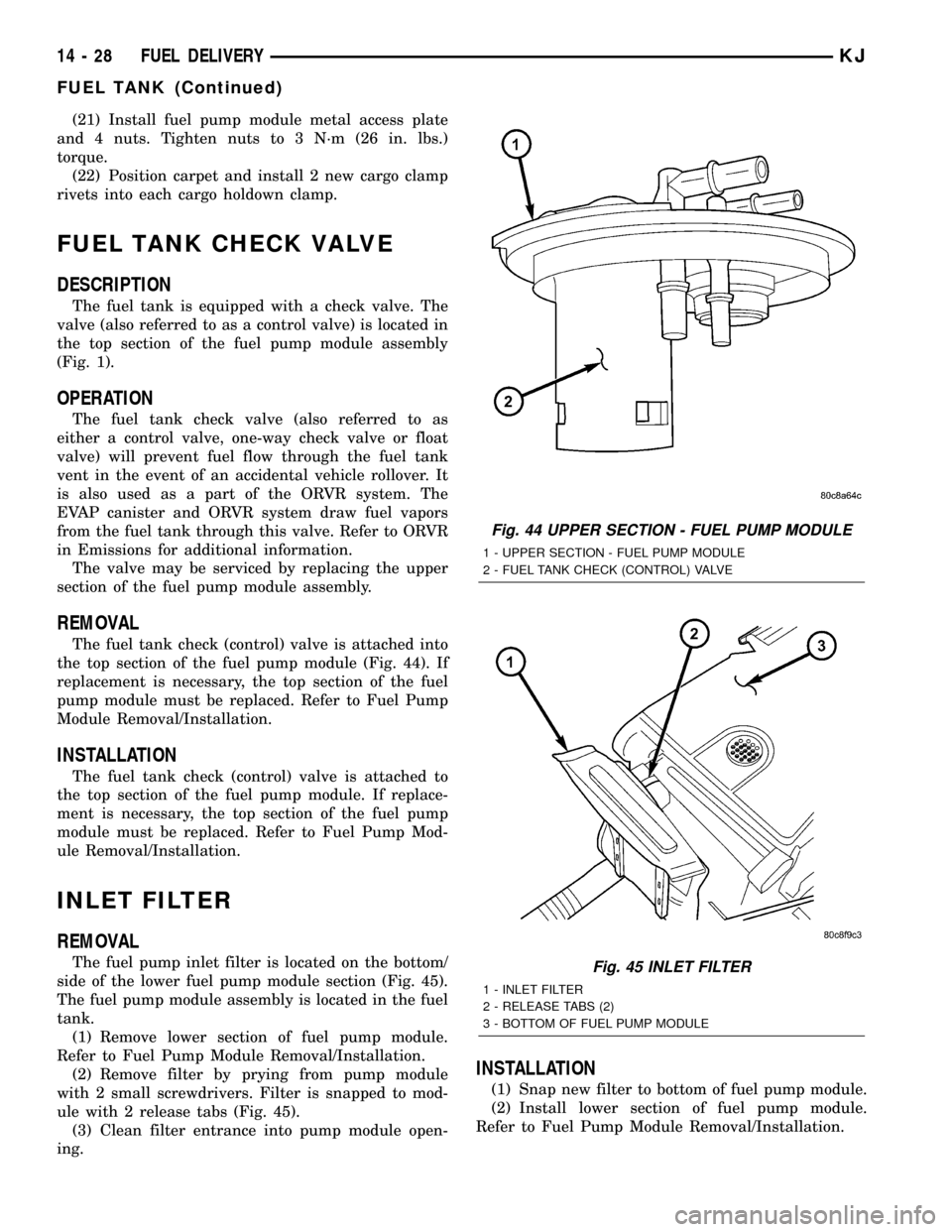
The fuel tank is equipped with a check valve. The
valve (also referred to as a control valve) is located in
the top section of the fuel pump module assembly
(Fig. 1).
OPERATION
The fuel tank check valve (also referred to as
either a control valve, one-way check valve or float
valve) will prevent fuel flow through the fuel tank
vent in the event of an accidental vehicle rollover. It
is also used as a part of the ORVR system. The
EVAP canister and ORVR system draw fuel vapors
from the fuel tank through this valve. Refer to ORVR
in Emissions for additional information.
The valve may be serviced by replacing the upper
section of the fuel pump module assembly.
REMOVAL
The fuel tank check (control) valve is attached into
the top section of the fuel pump module (Fig. 44). If
replacement is necessary, the top section of the fuel
pump module must be replaced. Refer to Fuel Pump
Module Removal/Installation.
INSTALLATION
The fuel tank check (control) valve is attached to
the top section of the fuel pump module. If replace-
ment is necessary, the top section of the fuel pump
module must be replaced. Refer to Fuel Pump Mod-
ule Removal/Installation.
INLET FILTER
REMOVAL
The fuel pump inlet filter is located on the bottom/
side of the lower fuel pump module section (Fig. 45).
The fuel pump module assembly is located in the fuel
tank.
(1) Remove lower section of fuel pump module.
Refer to Fuel Pump Module Removal/Installation.
(2) Remove filter by prying from pump module
with 2 small screwdrivers. Filter is snapped to mod-
ule with 2 release tabs (Fig. 45).
(3) Clean filter entrance into pump module open-
ing.
INSTALLATION
(1) Snap new filter to bottom of fuel pump module.
(2) Install lower section of fuel pump module.
Refer to Fuel Pump Module Removal/Installation.
Fig. 44 UPPER SECTION - FUEL PUMP MODULE
1 - UPPER SECTION - FUEL PUMP MODULE
2 - FUEL TANK CHECK (CONTROL) VALVE
Fig. 45 INLET FILTER
1 - INLET FILTER
2 - RELEASE TABS (2)
3 - BOTTOM OF FUEL PUMP MODULE
14 - 28 FUEL DELIVERYKJ
FUEL TANK (Continued)
Page 1730 of 1803
EVAPORATIVE EMISSIONS
TABLE OF CONTENTS
page page
EVAPORATIVE EMISSIONS
DESCRIPTION - EVAPORATION CONTROL
SYSTEM............................24
SPECIFICATIONS
TORQUE............................26
EVAP/PURGE SOLENOID
DESCRIPTION.........................27
OPERATION...........................27
REMOVAL.............................27
INSTALLATION.........................27
FUEL FILLER CAP
DESCRIPTION.........................27
OPERATION...........................27
LEAK DETECTION PUMP
DESCRIPTION.........................27
OPERATION...........................28
REMOVAL.............................28INSTALLATION.........................28
ORVR
DESCRIPTION.........................29
OPERATION...........................29
P C V VA LV E
DESCRIPTION.........................29
OPERATION...........................31
DIAGNOSIS AND TESTING - PCV VALVE.....31
REMOVAL.............................32
INSTALLATION.........................32
VACUUM LINES
DESCRIPTION.........................33
VAPOR CANISTER
DESCRIPTION.........................33
OPERATION...........................33
REMOVAL.............................33
INSTALLATION.........................33
EVAPORATIVE EMISSIONS
DESCRIPTION - EVAPORATION CONTROL
SYSTEM
The evaporation control system prevents the emis-
sion of fuel tank vapors into the atmosphere. When
fuel evaporates in the fuel tank, the vapors pass
through the control valve located in the top section of
the fuel pump module, through the fuel management
valve, and through vent hoses and tubes to a char-
coal filled evaporative canister. The canister tempo-
rarily holds the vapors. The Powertrain Control
Module (PCM) allows intake manifold vacuum to
draw vapors into the combustion chambers during
certain operating conditions.
Gas powered engines use a duty cycle purge sys-
tem. The PCM controls vapor flow by operating theduty cycle EVAP purge solenoid. Refer to Duty Cycle
EVAP Canister Purge Solenoid.
When equipped with certain emissions packages, a
Leak Detection Pump (LDP) will be used as part of
the evaporative system for OBD II requirements.
Also refer to Leak Detection Pump.
Vehicles powered with gasoline engines are also
equipped with ORVR (On-Board Refueling Vapor
Recovery). Refer to ORVR for additional information.
NOTE: The evaporative system uses specially man-
ufactured lines/hoses. If replacement becomes nec-
essary, only use fuel resistant, low permeation
hose.
Certain components can be found in (Fig. 1).
25 - 24 EVAPORATIVE EMISSIONSKJ
Page 1733 of 1803
EVAP/PURGE SOLENOID
DESCRIPTION
The duty cycle EVAP canister purge solenoid (DCP)
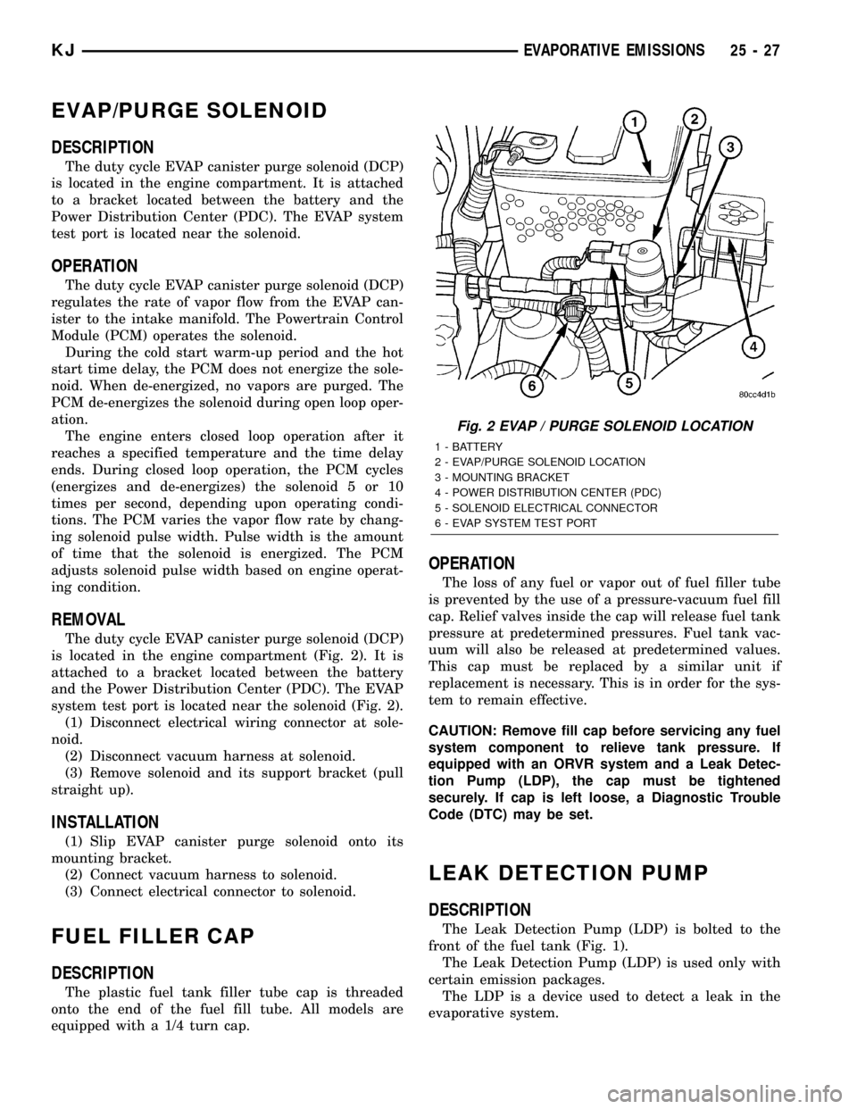
is located in the engine compartment. It is attached
to a bracket located between the battery and the
Power Distribution Center (PDC). The EVAP system
test port is located near the solenoid.
OPERATION
The duty cycle EVAP canister purge solenoid (DCP)
regulates the rate of vapor flow from the EVAP can-
ister to the intake manifold. The Powertrain Control
Module (PCM) operates the solenoid.
During the cold start warm-up period and the hot
start time delay, the PCM does not energize the sole-
noid. When de-energized, no vapors are purged. The
PCM de-energizes the solenoid during open loop oper-
ation.
The engine enters closed loop operation after it
reaches a specified temperature and the time delay
ends. During closed loop operation, the PCM cycles
(energizes and de-energizes) the solenoid 5 or 10
times per second, depending upon operating condi-
tions. The PCM varies the vapor flow rate by chang-
ing solenoid pulse width. Pulse width is the amount
of time that the solenoid is energized. The PCM
adjusts solenoid pulse width based on engine operat-
ing condition.
REMOVAL
The duty cycle EVAP canister purge solenoid (DCP)
is located in the engine compartment (Fig. 2). It is
attached to a bracket located between the battery
and the Power Distribution Center (PDC). The EVAP
system test port is located near the solenoid (Fig. 2).
(1) Disconnect electrical wiring connector at sole-
noid.
(2) Disconnect vacuum harness at solenoid.
(3) Remove solenoid and its support bracket (pull
straight up).
INSTALLATION
(1) Slip EVAP canister purge solenoid onto its
mounting bracket.
(2) Connect vacuum harness to solenoid.
(3) Connect electrical connector to solenoid.
FUEL FILLER CAP
DESCRIPTION
The plastic fuel tank filler tube cap is threaded
onto the end of the fuel fill tube. All models are
equipped with a 1/4 turn cap.
OPERATION
The loss of any fuel or vapor out of fuel filler tube
is prevented by the use of a pressure-vacuum fuel fill
cap. Relief valves inside the cap will release fuel tank
pressure at predetermined pressures. Fuel tank vac-
uum will also be released at predetermined values.
This cap must be replaced by a similar unit if
replacement is necessary. This is in order for the sys-
tem to remain effective.
CAUTION: Remove fill cap before servicing any fuel
system component to relieve tank pressure. If
equipped with an ORVR system and a Leak Detec-
tion Pump (LDP), the cap must be tightened
securely. If cap is left loose, a Diagnostic Trouble
Code (DTC) may be set.
LEAK DETECTION PUMP
DESCRIPTION
The Leak Detection Pump (LDP) is bolted to the
front of the fuel tank (Fig. 1).
The Leak Detection Pump (LDP) is used only with
certain emission packages.
The LDP is a device used to detect a leak in the
evaporative system.
Fig. 2 EVAP / PURGE SOLENOID LOCATION
1 - BATTERY
2 - EVAP/PURGE SOLENOID LOCATION
3 - MOUNTING BRACKET
4 - POWER DISTRIBUTION CENTER (PDC)
5 - SOLENOID ELECTRICAL CONNECTOR
6 - EVAP SYSTEM TEST PORT
KJEVAPORATIVE EMISSIONS 25 - 27
Page 1734 of 1803
The pump contains a 3 port solenoid, a pump that
contains a switch, a spring loaded canister vent valve
seal, 2 check valves and a spring/diaphragm.
OPERATION
Immediately after a cold start, engine temperature
between 40ÉF and 86ÉF, the 3 port solenoid is briefly
energized. This initializes the pump by drawing air
into the pump cavity and also closes the vent seal.
During non-test test conditions, the vent seal is held
open by the pump diaphragm assembly which pushes
it open at the full travel position. The vent seal will
remain closed while the pump is cycling. This is due
to the operation of the 3 port solenoid which prevents
the diaphragm assembly from reaching full travel.
After the brief initialization period, the solenoid is
de-energized, allowing atmospheric pressure to enter
the pump cavity. This permits the spring to drive the
diaphragm which forces air out of the pump cavity
and into the vent system. When the solenoid is ener-
gized and de-energized, the cycle is repeated creating
flow in typical diaphragm pump fashion. The pump
is controlled in 2 modes:
PUMP MODE:The pump is cycled at a fixed rate
to achieve a rapid pressure build in order to shorten
the overall test time.
TEST MODE:The solenoid is energized with a
fixed duration pulse. Subsequent fixed pulses occur
when the diaphragm reaches the switch closure
point.
The spring in the pump is set so that the system
will achieve an equalized pressure of about 7.5 inches
of water.
When the pump starts, the cycle rate is quite high.
As the system becomes pressurized pump rate drops.
If there is no leak the pump will quit. If there is a
leak, the test is terminated at the end of the test
mode.
If there is no leak, the purge monitor is run. If the
cycle rate increases due to the flow through the
purge system, the test is passed and the diagnostic is
complete.
The canister vent valve will unseal the system
after completion of the test sequence as the pump
diaphragm assembly moves to the full travel position.
REMOVAL
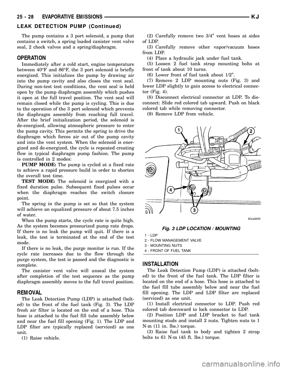
The Leak Detection Pump (LDP) is attached (bolt-
ed) to the front of the fuel tank (Fig. 3). The LDP
fresh air filter is located on the end of a hose. This
hose is attached to the fuel fill tube assembly below
and near the fuel fill opening (Fig. 1). The LDP and
LDP filter are typically replaced (serviced) as one
unit.
(1) Raise vehicle.(2) Carefully remove two 3/4º vent hoses at sides
of LDP.
(3) Carefully remove other vapor/vacuum hoses
from LDP.
(4) Place a hydraulic jack under fuel tank.
(5) Loosen 2 fuel tank strap mounting bolts at
front of tank about 10 turns.
(6) Lower front of fuel tank about 1/2º.
(7) Remove 2 LDP mounting nuts (Fig. 3) and
lower LDP slightly to gain access to electrical connec-
tor (Fig. 4).
(8) Disconnect electrical connector at LDP. To dis-
connect: Slide red colored tab upward. Push on black
colored tab while removing connector.
(9) Remove LDP from vehicle.
INSTALLATION
The Leak Detection Pump (LDP) is attached (bolt-
ed) to the front of the fuel tank. The LDP filter is
located on the end of a hose. This hose is attached to
the fuel fill tube assembly below and near the fuel
fill opening. The LDP and LDP filter are replaced
(serviced) as one unit.
(1) Install electrical connector to LDP. Push red
colored tab downward to lock connector to LDP.
(2) Position LDP and LDP bracket to fuel tank
mounting studs and install 2 nuts. Tighten nuts to 1
N´m (11 in. lbs.) torque.
(3) Raise fuel tank to body and tighten 2 strap
bolts to 61 N´m (45 ft. lbs.) torque.
Fig. 3 LDP LOCATION / MOUNTING
1 - LDP
2 - FLOW MANAGEMENT VALVE
3 - MOUNTING NUTS
4 - FRONT OF FUEL TANK
25 - 28 EVAPORATIVE EMISSIONSKJ
LEAK DETECTION PUMP (Continued)