2002 JEEP LIBERTY engine oil
[x] Cancel search: engine oilPage 1405 of 1803

(14) Gently rock and pull fuel rail until fuel injec-
tors just start to clear machined holes in intake man-
ifold.
(15) Remove fuel rail (with injectors attached)
from intake manifold.
(16) If fuel injectors are to be removed, refer to
Fuel Injector Removal/Installation.
3.7L
WARNING: THE FUEL SYSTEM IS UNDER CON-
STANT PRESSURE EVEN WITH ENGINE OFF.
BEFORE SERVICING FUEL RAIL, FUEL SYSTEM
PRESSURE MUST BE RELEASED.
CAUTION: The left and right fuel rails are replaced
as an assembly. Do not attempt to separate rail
halves at connector tube (Fig. 36). Due to design of
tube, it does not use any clamps. Never attempt to
install a clamping device of any kind to tube. When
removing fuel rail assembly for any reason, be care-
ful not to bend or kink tube.
(1) Remove fuel tank filler tube cap.
(2) Perform Fuel System Pressure Release Proce-
dure.
(3) Remove negative battery cable at battery.
(4) Remove air duct at throttle body air box.
(5) Remove air box at throttle body.
(6) Disconnect fuel line latch clip and fuel line at
fuel rail. A special tool will be necessary for fuel line
disconnection. Refer to Quick-Connect Fittings.
(7) Remove necessary vacuum lines at throttle
body.
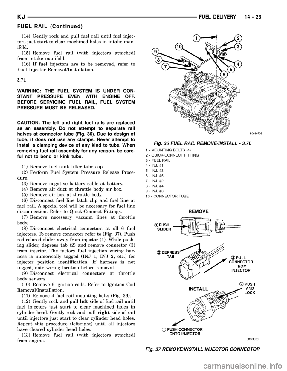
(8) Disconnect electrical connectors at all 6 fuel
injectors. To remove connector refer to (Fig. 37). Push
red colored slider away from injector (1). While push-
ing slider, depress tab (2) and remove connector (3)
from injector. The factory fuel injection wiring har-
ness is numerically tagged (INJ 1, INJ 2, etc.) for
injector position identification. If harness is not
tagged, note wiring location before removal.
(9) Disconnect electrical connectors at throttle
body sensors.
(10) Remove 6 ignition coils. Refer to Ignition Coil
Removal/Installation.
(11) Remove 4 fuel rail mounting bolts (Fig. 36).
(12) Gently rock and pullleftside of fuel rail until
fuel injectors just start to clear machined holes in
cylinder head. Gently rock and pullrightside of rail
until injectors just start to clear cylinder head holes.
Repeat this procedure (left/right) until all injectors
have cleared cylinder head holes.
(13) Remove fuel rail (with injectors attached)
from engine.
Fig. 36 FUEL RAIL REMOVE/INSTALL - 3.7L
1 - MOUNTING BOLTS (4)
2 - QUICK-CONNECT FITTING
3 - FUEL RAIL
4 - INJ. #1
5 - INJ. #3
6 - INJ. #5
7 - INJ. #2
8 - INJ. #4
9 - INJ. #6
10 - CONNECTOR TUBE
Fig. 37 REMOVE/INSTALL INJECTOR CONNECTOR
KJFUEL DELIVERY 14 - 23
FUEL RAIL (Continued)
Page 1406 of 1803

(14) If fuel injectors are to be removed, refer to
Fuel Injector Removal/Installation.
INSTALLATION
2.4L Engine
(1) If fuel injectors are to be installed, refer to Fuel
Injector Removal/Installation.
(2) Clean out fuel injector machined bores in
intake manifold.
(3) Apply a small amount of engine oil to each fuel
injector o-ring. This will help in fuel rail installation.
(4) Position fuel rail/fuel injector assembly to
machined injector openings in intake manifold.
(5) Guide each injector into cylinder head. Be care-
ful not to tear injector o-rings.
(6) Push fuel rail down until fuel injectors have
bottomed on shoulders.
(7) Install 2 fuel rail mounting bolts and tighten.
Refer to torque specifications.
(8) Connect electrical connectors at all fuel injec-
tors. To install connector, refer to (Fig. 37). Push con-
nector onto injector (1) and then push and lock red
colored slider (2). Verify connector is locked to injec-
tor by lightly tugging on connector.
(9) Snap 2 injection wiring harness clips (Fig. 35)
into brackets.
(10) Connect 2 main engine harness connectors at
rear of intake manifold (Fig. 34).
(11) Tighten 5 intake manifold mounting bolts.
Refer to Engine Torque Specifications.
(12) Install PCV valve and hose.
(13) Install thermostat and radiator hose. Fill with
coolant. Refer to Cooling.
(14) Connect necessary vacuum lines to throttle
body.
(15) Connect fuel line latch clip and fuel line to
fuel rail. Refer to Quick-Connect Fittings.
(16) Install air duct to throttle body.
(17) Connect battery cable to battery.
(18) Start engine and check for leaks.
3.7L Engine
(1) If fuel injectors are to be installed, refer to Fuel
Injector Removal/Installation.
(2) Clean out fuel injector machined bores in
intake manifold.
(3) Apply a small amount of engine oil to each fuel
injector o-ring. This will help in fuel rail installation.
(4) Position fuel rail/fuel injector assembly to
machined injector openings in cylinder head.
(5) Guide each injector into cylinder head. Be care-
ful not to tear injector o-rings.
(6) Pushrightside of fuel rail down until fuel
injectors have bottomed on cylinder head shoulder.Pushleftfuel rail down until injectors have bot-
tomed on cylinder head shoulder.
(7) Install 4 fuel rail mounting bolts and tighten.
Refer to torque specifications.
(8) Install 6 ignition coils. Refer to Ignition Coil
Removal/Installation.
(9) Connect electrical connectors to throttle body.
(10) Connect electrical connectors at all fuel injec-
tors. To install connector, refer to (Fig. 37). Push con-
nector onto injector (1) and then push and lock red
colored slider (2). Verify connector is locked to injec-
tor by lightly tugging on connector.
(11) Connect necessary vacuum lines to throttle
body.
(12) Connect fuel line latch clip and fuel line to
fuel rail. Refer to Quick-Connect Fittings.
(13) Install air box to throttle body.
(14) Install air duct to air box.
(15) Connect battery cable to battery.
(16) Start engine and check for leaks.
FUEL TANK
DESCRIPTION
The fuel tank is constructed of a plastic material.
Its main functions are for fuel storage and for place-
ment of the fuel pump module, and certain ORVR
components.
OPERATION
All models pass a full 360 degree rollover test
without fuel leakage. To accomplish this, fuel and
vapor flow controls are required for all fuel tank con-
nections.
A check (control) valve is mounted into the top sec-
tion of the 2±piece fuel pump module. Refer to Fuel
Tank Check Valve for additional information.
An evaporation control system is connected to the
fuel tank to reduce emissions of fuel vapors into the
atmosphere. When fuel evaporates from the fuel
tank, vapors pass through vent hoses or tubes to a
charcoal canister where they are temporarily held.
When the engine is running, the vapors are drawn
into the intake manifold. Certain models are also
equipped with a self-diagnosing system using a Leak
Detection Pump (LDP) and/or an ORVR system.
Refer to Emission Control System for additional
information.
14 - 24 FUEL DELIVERYKJ
FUEL RAIL (Continued)
Page 1414 of 1803

INSTALLATION
2.4L
(1) Clean out machined hole in engine block.
(2) Apply a small amount of engine oil to sensor
o-ring.(3) Install sensor into engine block with a slight
rocking action. Do not twist sensor into position as
damage to o-ring may result.
CAUTION: Before tightening sensor mounting bolt,
be sure sensor is completely flush to cylinder
block. If sensor is not flush, damage to sensor
mounting tang may result.
(4) Install mounting bolt and tighten to 28 N´m
(21 ft. lbs.) torque.
(5) Connect electrical connector to sensor.
3.7L
(1) Clean out machined hole in engine block.
(2) Apply a small amount of engine oil to sensor
o-ring.
(3) Install sensor into engine block with a slight
rocking and twisting action.
CAUTION: Before tightening sensor mounting bolt,
be sure sensor is completely flush to cylinder
block. If sensor is not flush, damage to sensor
mounting tang may result.
(4) Install mounting bolt and tighten to 28 N´m
(21 ft. lbs.) torque.
(5) Connect electrical connector to sensor.
(6) Lower vehicle.
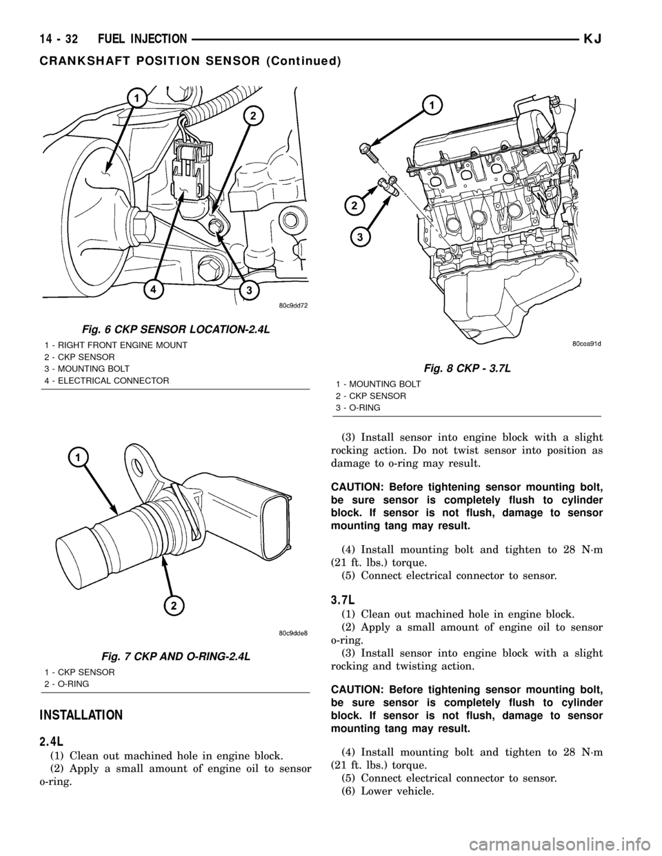
Fig. 6 CKP SENSOR LOCATION-2.4L
1 - RIGHT FRONT ENGINE MOUNT
2 - CKP SENSOR
3 - MOUNTING BOLT
4 - ELECTRICAL CONNECTOR
Fig. 7 CKP AND O-RING-2.4L
1 - CKP SENSOR
2 - O-RING
Fig. 8 CKP - 3.7L
1 - MOUNTING BOLT
2 - CKP SENSOR
3 - O-RING
14 - 32 FUEL INJECTIONKJ
CRANKSHAFT POSITION SENSOR (Continued)
Page 1416 of 1803

REMOVAL
(1) Remove fuel rail. Refer to Fuel Injector Rail
Removal.
(2) Disconnect clip(s) that retain fuel injector(s) to
fuel rail (Fig. 10).
INSTALLATION
(1) Install fuel injector(s) into fuel rail assembly
and install retaining clip(s).
(2) If same injector(s) is being reinstalled, install
new o-ring(s).
(3) Apply a small amount of clean engine oil to
each injector o-ring. This will aid in installation.
(4) Install fuel rail. Refer to Fuel Rail Installation.
(5) Start engine and check for fuel leaks.
FUEL PUMP RELAY
DESCRIPTION
The 5±pin, 12±volt, fuel pump relay is located in
the Power Distribution Center (PDC). Refer to the
label on the PDC cover for relay location.
OPERATION
The Powertrain Control Module (PCM) energizes
the electric fuel pump through the fuel pump relay.
The fuel pump relay is energized by first applying
battery voltage to it when the ignition key is turnedON, and then applying a ground signal to the relay
from the PCM.
Whenever the ignition key is turned ON, the elec-
tric fuel pump will operate. But, the PCM will shut-
down the ground circuit to the fuel pump relay in
approximately 1±3 seconds unless the engine is oper-
ating or the starter motor is engaged.
DIAGNOSIS AND TESTING - FUEL PUMP
RELAY
For procedures, refer to ASD Relay Diagnosis and
Testing in the Ignition section.
REMOVAL
The fuel pump relay is located in the Power Distri-
bution Center (PDC) (Fig. 11). Refer to label on PDC
cover for relay location.
(1) Remove PDC cover.
(2) Remove relay from PDC.
(3) Check condition of relay terminals and PDC
connector terminals for damage or corrosion. Repair
if necessary before installing relay.
(4) Check for pin height (pin height should be the
same for all terminals within the PDC connector).
Repair if necessary before installing relay.
INSTALLATION
The fuel pump relay is located in the Power Distri-
bution Center (PDC). Refer to label on PDC cover for
relay location.
(1) Install relay to PDC.
(2) Install cover to PDC.
Fig. 10 INJECTOR RETAINING CLIP
1 - PLIERS
2 - INJECTOR CLIP
3 - FUEL INJECTOR
4 - FUEL RAIL - TYPICAL
Fig. 11 POWER DISTRIBUTION CENTER (PDC)
1 - BATTERY
2 - PDC
3 - PDC COVER
14 - 34 FUEL INJECTIONKJ
FUEL INJECTOR (Continued)
Page 1425 of 1803

WARNING: THE EXHAUST MANIFOLD, EXHAUST
PIPES AND CATALYTIC CONVERTER BECOME
VERY HOT DURING ENGINE OPERATION. ALLOW
ENGINE TO COOL BEFORE REMOVING OXYGEN
SENSOR.
(1) Raise and support vehicle.
(2) Disconnect wire connector from O2S sensor.
CAUTION: When disconnecting sensor electrical
connector, do not pull directly on wire going into
sensor.
(3) Remove O2S sensor with an oxygen sensor
removal and installation tool.
(4) Clean threads in exhaust pipe using appropri-
ate tap.
INSTALLATION
Threads of new oxygen sensors are factory coated
with anti-seize compound to aid in removal.DO
NOT add any additional anti-seize compound to
threads of a new oxygen sensor.
(1) Install O2S sensor. Tighten to 30 N´m (22 ft.
lbs.) torque.
(2) Connect O2S sensor wire connector.
(3) Lower vehicle.
THROTTLE BODY
DESCRIPTION
The throttle body is located on the intake manifold.
Fuel does not enter the intake manifold through the
throttle body. Fuel is sprayed into the manifold by
the fuel injectors.
OPERATION
Filtered air from the air cleaner enters the intake
manifold through the throttle body. The throttle body
contains an air control passage controlled by an Idle
Air Control (IAC) motor. The air control passage is
used to supply air for idle conditions. A throttle valve
(plate) is used to supply air for above idle conditions.
Certain sensors are attached to the throttle body.
The accelerator pedal cable, speed control cable and
transmission control cable (when equipped) are con-
nected to the throttle body linkage arm.
A (factory adjusted) set screw is used to mechani-
cally limit the position of the throttle body throttle
plate.Never attempt to adjust the engine idle
speed using this screw.All idle speed functions are
controlled by the PCM.
REMOVAL
2.4L
A (factory adjusted) set screw is used to mechani-
cally limit the position of the throttle body throttle
plate.Never attempt to adjust the engine idle
speed using this screw.All idle speed functions are
controlled by the Powertrain Control Module (PCM).
(1) Remove air cleaner tube at throttle body.
(2) Disconnect throttle body electrical connectors
at IAC motor and TPS.
(3) Remove all control cables from throttle body
(lever) arm. Refer to the Accelerator Pedal and Throt-
tle Cable section for removal/installation procedures.
(4) Disconnect necessary vacuum lines at throttle
body.
(5) Remove 3 throttle body mounting bolts (Fig.
23).
(6) Remove throttle body from intake manifold.
(7) Check condition of old throttle body-to-intake
manifold o-ring.
3.7L
A (factory adjusted) set screw is used to mechani-
cally limit the position of the throttle body throttle
plate.Never attempt to adjust the engine idle
speed using this screw.All idle speed functions are
controlled by the Powertrain Control Module (PCM).
(1) Remove air cleaner tube at throttle body.
(2) Disconnect throttle body electrical connectors
at IAC motor and TPS.
Fig. 23 THROTTLE BODY MOUNTING BOLTS - 2.4L
1 - THROTTLE BODY
2 - IGNITION COIL
3 - MOUNTING BOLTS (3)
KJFUEL INJECTION 14 - 43
OXYGEN SENSOR (Continued)
Page 1431 of 1803

STEERING
TABLE OF CONTENTS
page page
STEERING
DESCRIPTION..........................1
OPERATION............................1
DIAGNOSIS AND TESTING
DIAGNOSIS AND TESTING - POWER
STEERING SYSTEM....................1DIAGNOSIS AND TESTING - POWER
STEERING FLOW AND PRESSURE........3
COLUMN...............................5
GEAR.................................13
LINKAGE..............................16
PUMP.................................17
STEERING
DESCRIPTION
Power steering systems consist of:
²Steering column & Intermediate Shaft
²Rack and pinion steering gear
²Belt driven hydraulic steering pump
²Pump pressure, supply and return hoses
²Oil Cooler
OPERATION
The steering column intermediate shaft attaches
the steering column to the gear pinion. The rotation
of the pinion moves the gear rack from side-to-side.
This lateral action of the rack pushes and pulls the
tie rods to change the direction of the front wheels.
Power assist is provided by an engine mounted
hydraulic pump. The pump supplies hydraulic fluid
to the steering gear. All vehicles are equipped with
an oil cooler.
DIAGNOSIS AND TESTING
DIAGNOSIS AND TESTING - POWER STEERING SYSTEM
STEERING NOISE
There is some noise in all power steering systems. One of the most common is a hissing sound evident at a
standstill/parking, or when the steering is at the end of it's travel. Hiss is a high frequency noise similar to that
of a water tap being closed slowly. The noise is present in all valves that have a high velocity fluid passing through
an orifice. There is no relationship between this noise and steering performance.
CONDITION POSSIBLE CAUSES CORRECTION
OBJECTIONAL HISS OR
WHISTLE1. Steering intermediate shaft to dash panel
seal.1. Check and repair seal at dash
panel.
2. Noisy valve in power steering gear. 2. Replace steering gear.
1. Gear mounting bolts loose. 1. Tighten bolts to specification.
2. Loose or damaged suspension
components.2. Inspect and repair suspension.
3. Internal gear noise. 3. Replace steering gear.
4. Loose or damaged intermediate shaft or
column.4. Inspect and repair or replace.
MOAN Pressure hose in contact with other
components.Reposition hose.
CHIRP OR SQUEAL 1. Loose belt. 1. Adjust or replace.
KJSTEERING 19 - 1
Page 1468 of 1803

DIAGNOSIS AND TESTING - WIND NOISE
Wind noise is the result of most air leaks. Air leaks
can be caused by poor sealing, improper body compo-
nent alignment, body seam porosity, or missing plugs
in the engine compartment or door hinge pillar areas.
All body sealing points should be airtight in normal
driving conditions. Moving sealing surfaces will not
always seal airtight under all conditions. At times,
side glass or door seals will allow wind noise to be
noticed in the passenger compartment during high
cross winds. Over compensating on door or glass
adjustments to stop wind noise that occurs under
severe conditions can cause premature seal wear and
excessive closing or latching effort. After a repair pro-
cedure has been performed, test vehicle to verify
noise has stopped before returning vehicle to use.
Wind noise can also be caused by improperly fitted
exterior moldings or body ornamentation. Loose
moldings can flutter, creating a buzzing or chattering
noise. An open cavity or protruding edge can create a
whistling or howling noise. Inspect the exterior of the
vehicle to verify that these conditions do not exist.
VISUAL INSPECTION BEFORE TESTS
Verify that floor and body plugs are in place and
body components are aligned and sealed. If compo-
nent alignment or sealing is necessary, refer to the
appropriate section of this group for proper proce-
dures.
ROAD TESTING WIND NOISE
(1) Drive the vehicle to verify the general location
of the wind noise.
(2) Apply 50 mm (2 in.) masking tape in 150 mm
(6 in.) lengths along weatherstrips, weld seams or
moldings. After each length is applied, drive the vehi-
cle. If noise goes away after a piece of tape is applied,
remove tape, locate, and repair defect.
POSSIBLE CAUSE OF WIND NOISE
²Moldings standing away from body surface can
catch wind and whistle.
²Gaps in sealed areas behind overhanging body
flanges can cause wind-rushing sounds.
²Misaligned movable components.
²Missing or improperly installed plugs in pillars.
²Weld burn through holes.
STANDARD PROCEDURE
STANDARD PROCEDURE - BODY LUBRICATION
All mechanisms and linkages should be lubricated
when necessary. This will maintain ease of operation
and provide protection against rust and excessivewear. The weatherstrip seals should be lubricated to
prolong their life as well as to improve door sealing.
All applicable exterior and interior vehicle operat-
ing mechanisms should be inspected and cleaned.
Pivot/sliding contact areas on the mechanisms should
then be lubricated.
(1) When necessary, lubricate the operating mech-
anisms with the specified lubricants.
(2) Apply silicone lubricant to a cloth and wipe it
on door seals to avoid over-spray that can soil pas-
senger's clothing.
(3) Before applying lubricant, the component
should be wiped clean. After lubrication, any excess
lubricant should be removed.
(4) The hood latch, latch release mechanism, latch
striker, and safety latch should be lubricated period-
ically.
(5) The door lock cylinders should be lubricated
twice each year (preferably autumn and spring).
²Spray a small amount of lock cylinder lubricant
directly into the lock cylinder.
²Apply a small amount to the key and insert it
into the lock cylinder.
²Rotate it to the locked position and then back to
the unlocked position several times.
²Remove the key. Wipe the lubricant from it with
a clean cloth to avoid soiling of clothing.
STANDARD PROCEDURE - HEAT STAKING
(1) Remove trim panel.
(2) Bend or move the trim panel components at
the heat staked joints. Observe the heat staked loca-
tions and/or component seams for looseness.
(3) Heat stake the components.
(a) If the heat staked or component seam loca-
tion is loose, hold the two components tightly
together and using a soldering gun with a flat tip,
melt the material securing the components
together. Do not over heat the affected area, dam-
age to the exterior of the trim panel may occur.
(b) If the heat staked material is broken or miss-
ing, use a hot glue gun to apply new material to
the area to be repaired. The panels that are being
heat staked must be held together while the apply-
ing the glue. Once the new material is in place, it
may be necessary to use a soldering gun to melt
the newly applied material. Do not over heat the
affected area, damage to the exterior of the trim
panel may occur.
(4) Allow the repaired area to cool and verify the
repair.
(5) Install trim panel.
KJBODY 23 - 3
BODY (Continued)
Page 1653 of 1803

HEATING & AIR CONDITIONING
TABLE OF CONTENTS
page page
HEATING & AIR CONDITIONING
DESCRIPTION
DESCRIPTION - HEATER AND AIR
CONDITIONER........................1
DESCRIPTION - COOLING SYSTEM
REQUIREMENTS.......................1
DESCRIPTION - REFRIGERANT SYSTEM
SERVICE PORT........................2
OPERATION
OPERATION - HEATER AND AIR
CONDITIONER........................2
OPERATION - REFRIGERANT SYSTEM
SERVICE PORT........................2
DIAGNOSIS AND TESTING
DIAGNOSIS AND TESTING - A/C
PERFORMANCE.......................2DIAGNOSIS AND TESTING - HEATER
PERFORMANCE.......................6
DIAGNOSIS AND TESTING - VACUUM
SYSTEM.............................6
STANDARD PROCEDURE - DIODE
REPLACEMENT.......................9
SPECIFICATIONS
A/C APPLICATION TABLE................9
SPECIFICATIONS.....................10
CONTROLS.............................11
DISTRIBUTION..........................29
PLUMBING.............................38
HEATING & AIR
CONDITIONING
DESCRIPTION
DESCRIPTION - HEATER AND AIR
CONDITIONER
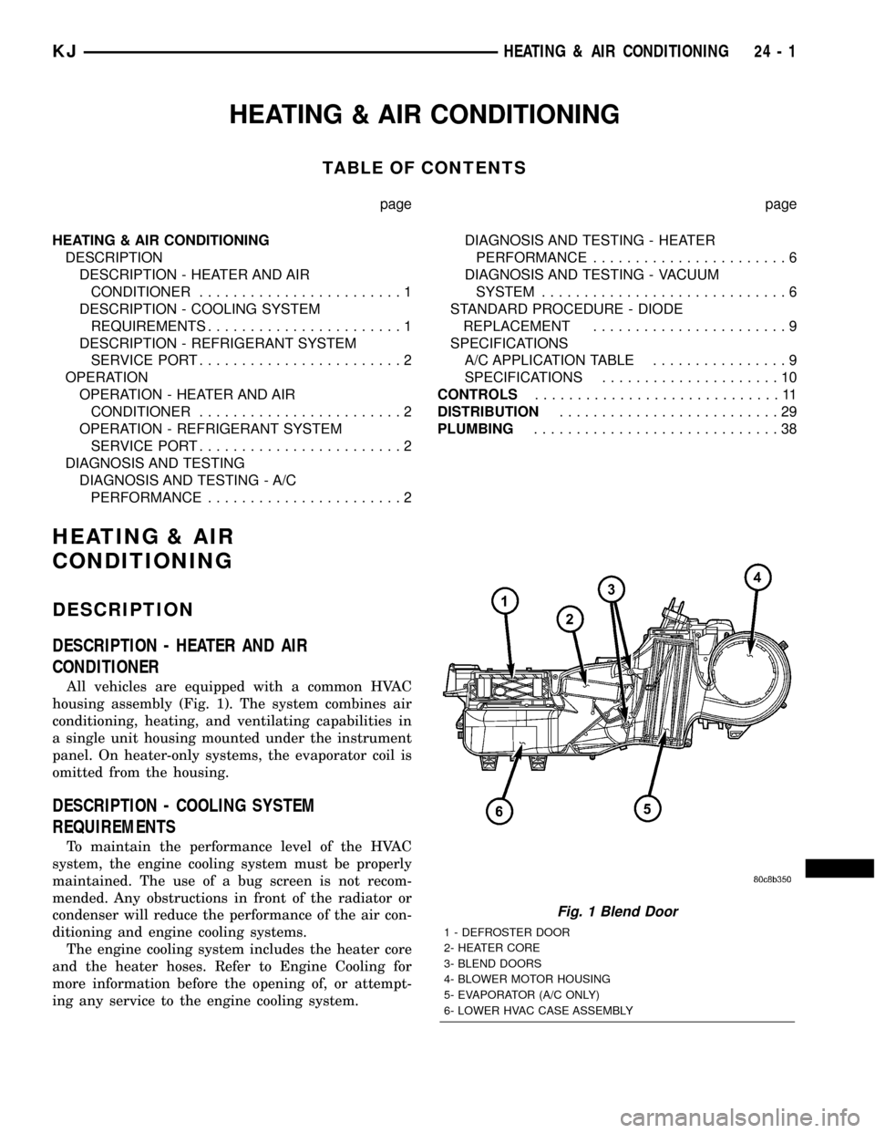
All vehicles are equipped with a common HVAC
housing assembly (Fig. 1). The system combines air
conditioning, heating, and ventilating capabilities in
a single unit housing mounted under the instrument
panel. On heater-only systems, the evaporator coil is
omitted from the housing.
DESCRIPTION - COOLING SYSTEM
REQUIREMENTS
To maintain the performance level of the HVAC
system, the engine cooling system must be properly
maintained. The use of a bug screen is not recom-
mended. Any obstructions in front of the radiator or
condenser will reduce the performance of the air con-
ditioning and engine cooling systems.
The engine cooling system includes the heater core
and the heater hoses. Refer to Engine Cooling for
more information before the opening of, or attempt-
ing any service to the engine cooling system.
Fig. 1 Blend Door
1 - DEFROSTER DOOR
2- HEATER CORE
3- BLEND DOORS
4- BLOWER MOTOR HOUSING
5- EVAPORATOR (A/C ONLY)
6- LOWER HVAC CASE ASSEMBLY
KJHEATING & AIR CONDITIONING 24 - 1