2002 JEEP LIBERTY oil
[x] Cancel search: oilPage 1251 of 1803
NOTE: Check for sharp edges on the keeper
grooves. Remove any burrs from the valve stem
before removing the valve from the cylinder head.
(7) Remove the valve from the cylinder head.
NOTE: The valve stem seals are common between
intake and exhaust.
(8) Remove the valve stem seal. Mark the valve for
proper installation.
TESTING VALVE SPRINGS
NOTE: Whenever the valves are removed from the
cylinder head it is recommended that the valve
springs be inspected and tested for reuse.
Inspect the valve springs for physical signs of wear
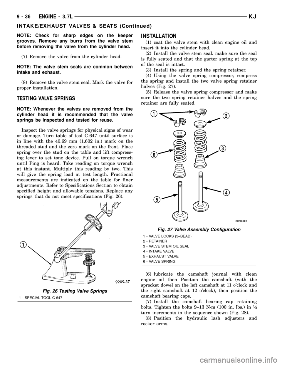
or damage. Turn table of tool C-647 until surface is
in line with the 40.69 mm (1.602 in.) mark on the
threaded stud and the zero mark on the front. Place
spring over the stud on the table and lift compress-
ing lever to set tone device. Pull on torque wrench
until Ping is heard. Take reading on torque wrench
at this instant. Multiply this reading by two. This
will give the spring load at test length. Fractional
measurements are indicated on the table for finer
adjustments. Refer to Specifications Section to obtain
specified height and allowable tensions. Replace any
springs that do not meet specifications (Fig. 26).
INSTALLATION
(1) coat the valve stem with clean engine oil and
insert it into the cylinder head.
(2) Install the valve stem seal. make sure the seal
is fully seated and that the garter spring at the top
of the seal is intact.
(3) Install the spring and the spring retainer.
(4) Using the valve spring compressor, compress
the spring and install the two valve spring retainer
halves (Fig. 27).
(5) Release the valve spring compressor and make
sure the two spring retainer halves and the spring
retainer are fully seated.
(6) lubricate the camshaft journal with clean
engine oil then Position the camshaft (with the
sprocket dowel on the left camshaft at 11 o'clock and
the right camshaft at 12 o'clock), then position the
camshaft bearing caps.
(7) Install the camshaft bearing cap retaining
bolts. Tighten the bolts 9±13 N´m (100 in. lbs.) in ó
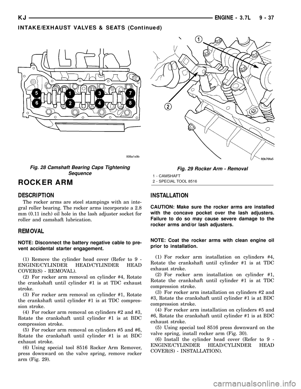
turn increments in the sequence shown (Fig. 28).
(8) Position the hydraulic lash adjusters and
rocker arms.
Fig. 26 Testing Valve Springs
1 - SPECIAL TOOL C-647
Fig. 27 Valve Assembly Configuration
1 - VALVE LOCKS (3±BEAD)
2 - RETAINER
3 - VALVE STEM OIL SEAL
4 - INTAKE VALVE
5 - EXHAUST VALVE
6 - VALVE SPRING
9 - 36 ENGINE - 3.7LKJ
INTAKE/EXHAUST VALVES & SEATS (Continued)
Page 1252 of 1803
ROCKER ARM
DESCRIPTION
The rocker arms are steel stampings with an inte-
gral roller bearing. The rocker arms incorporate a 2.8
mm (0.11 inch) oil hole in the lash adjuster socket for
roller and camshaft lubrication.
REMOVAL
NOTE: Disconnect the battery negative cable to pre-
vent accidental starter engagement.
(1) Remove the cylinder head cover (Refer to 9 -
ENGINE/CYLINDER HEAD/CYLINDER HEAD
COVER(S) - REMOVAL).
(2) For rocker arm removal on cylinder #4, Rotate
the crankshaft until cylinder #1 is at TDC exhaust
stroke.
(3) For rocker arm removal on cylinder #1, Rotate
the crankshaft until cylinder #1 is at TDC compres-
sion stroke.
(4) For rocker arm removal on cylinders #2 and #3,
Rotate the crankshaft until cylinder #1 is at BDC
compression stroke.
(5) For rocker arm removal on cylinders #5 and #6,
Rotate the crankshaft until cylinder #1 is at BDC
exhaust stroke.
(6) Using special tool 8516 Rocker Arm Remover,
press downward on the valve spring, remove rocker
arm (Fig. 29).
INSTALLATION
CAUTION: Make sure the rocker arms are installed
with the concave pocket over the lash adjusters.
Failure to do so may cause severe damage to the
rocker arms and/or lash adjusters.
NOTE: Coat the rocker arms with clean engine oil
prior to installation.
(1) For rocker arm installation on cylinders #4,
Rotate the crankshaft until cylinder #1 is at TDC
exhaust stroke.
(2) For rocker arm installation on cylinder #1,
Rotate the crankshaft until cylinder #1 is at TDC
compression stroke.
(3) For rocker arm installation on cylinders #2 and
#3, Rotate the crankshaft until cylinder #1 is at BDC
compression stroke.
(4) For rocker arm installation on cylinders #5 and
#6, Rotate the crankshaft until cylinder #1 is at BDC
exhaust stroke.
(5) Using special tool 8516 press downward on the
valve spring, install rocker arm (Fig. 30).
(6) Install the cylinder head cover (Refer to 9 -
ENGINE/CYLINDER HEAD/CYLINDER HEAD
COVER(S) - INSTALLATION).
Fig. 28 Camshaft Bearing Caps Tightening
SequenceFig. 29 Rocker Arm - Removal
1 - CAMSHAFT
2 - SPECIAL TOOL 8516
KJENGINE - 3.7L 9 - 37
INTAKE/EXHAUST VALVES & SEATS (Continued)
Page 1254 of 1803
ENGINE BLOCK
DESCRIPTION
The cylinder block is made of cast iron. The block
is a closed deck design with the left bank forward. To
provide high rigidity and improved NVH an
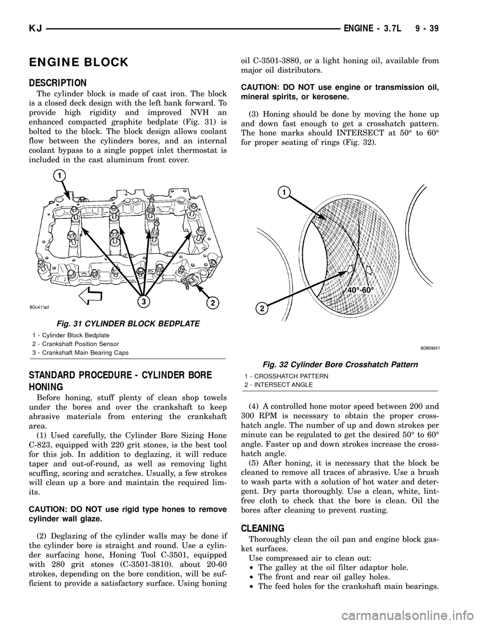
enhanced compacted graphite bedplate (Fig. 31) is
bolted to the block. The block design allows coolant
flow between the cylinders bores, and an internal
coolant bypass to a single poppet inlet thermostat is
included in the cast aluminum front cover.
STANDARD PROCEDURE - CYLINDER BORE
HONING
Before honing, stuff plenty of clean shop towels
under the bores and over the crankshaft to keep
abrasive materials from entering the crankshaft
area.
(1) Used carefully, the Cylinder Bore Sizing Hone
C-823, equipped with 220 grit stones, is the best tool
for this job. In addition to deglazing, it will reduce
taper and out-of-round, as well as removing light
scuffing, scoring and scratches. Usually, a few strokes
will clean up a bore and maintain the required lim-
its.
CAUTION: DO NOT use rigid type hones to remove
cylinder wall glaze.
(2) Deglazing of the cylinder walls may be done if
the cylinder bore is straight and round. Use a cylin-
der surfacing hone, Honing Tool C-3501, equipped
with 280 grit stones (C-3501-3810). about 20-60
strokes, depending on the bore condition, will be suf-
ficient to provide a satisfactory surface. Using honingoil C-3501-3880, or a light honing oil, available from
major oil distributors.
CAUTION: DO NOT use engine or transmission oil,
mineral spirits, or kerosene.
(3) Honing should be done by moving the hone up
and down fast enough to get a crosshatch pattern.
The hone marks should INTERSECT at 50É to 60É
for proper seating of rings (Fig. 32).
(4) A controlled hone motor speed between 200 and
300 RPM is necessary to obtain the proper cross-
hatch angle. The number of up and down strokes per
minute can be regulated to get the desired 50É to 60É
angle. Faster up and down strokes increase the cross-
hatch angle.
(5) After honing, it is necessary that the block be
cleaned to remove all traces of abrasive. Use a brush
to wash parts with a solution of hot water and deter-
gent. Dry parts thoroughly. Use a clean, white, lint-
free cloth to check that the bore is clean. Oil the
bores after cleaning to prevent rusting.
CLEANING
Thoroughly clean the oil pan and engine block gas-
ket surfaces.
Use compressed air to clean out:
²The galley at the oil filter adaptor hole.
²The front and rear oil galley holes.
²The feed holes for the crankshaft main bearings.
Fig. 31 CYLINDER BLOCK BEDPLATE
1 - Cylinder Block Bedplate
2 - Crankshaft Position Sensor
3 - Crankshaft Main Bearing Caps
Fig. 32 Cylinder Bore Crosshatch Pattern
1 - CROSSHATCH PATTERN
2 - INTERSECT ANGLE
KJENGINE - 3.7L 9 - 39
Page 1255 of 1803
Once the block has been completely cleaned, apply
Loctite PST pipe sealant with Teflon 592 to the
threads of the front and rear oil galley plugs. Tighten
the plugs to 34 N´m (25 ft. lbs.) torque.
INSPECTION
(1) It is mandatory to use a dial bore gauge to
measure each cylinder bore diameter. To correctly
select the proper size piston, a cylinder bore gauge,
capable of reading in 0.003 mm (.0001 in.) INCRE-
MENTS is required. If a bore gauge is not available,
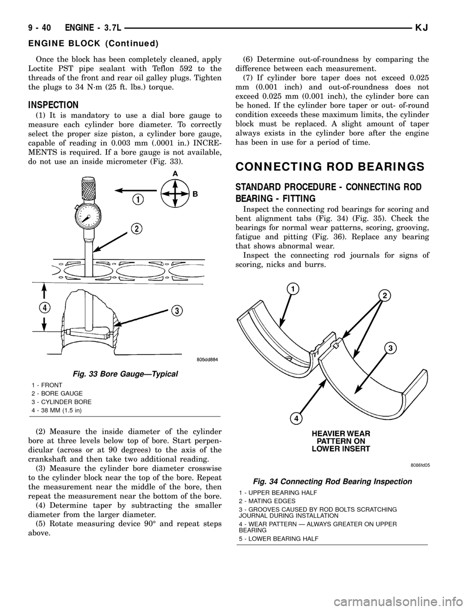
do not use an inside micrometer (Fig. 33).
(2) Measure the inside diameter of the cylinder
bore at three levels below top of bore. Start perpen-
dicular (across or at 90 degrees) to the axis of the
crankshaft and then take two additional reading.
(3) Measure the cylinder bore diameter crosswise
to the cylinder block near the top of the bore. Repeat
the measurement near the middle of the bore, then
repeat the measurement near the bottom of the bore.
(4) Determine taper by subtracting the smaller
diameter from the larger diameter.
(5) Rotate measuring device 90É and repeat steps
above.(6) Determine out-of-roundness by comparing the
difference between each measurement.
(7) If cylinder bore taper does not exceed 0.025
mm (0.001 inch) and out-of-roundness does not
exceed 0.025 mm (0.001 inch), the cylinder bore can
be honed. If the cylinder bore taper or out- of-round
condition exceeds these maximum limits, the cylinder
block must be replaced. A slight amount of taper
always exists in the cylinder bore after the engine
has been in use for a period of time.
CONNECTING ROD BEARINGS
STANDARD PROCEDURE - CONNECTING ROD
BEARING - FITTING
Inspect the connecting rod bearings for scoring and
bent alignment tabs (Fig. 34) (Fig. 35). Check the
bearings for normal wear patterns, scoring, grooving,
fatigue and pitting (Fig. 36). Replace any bearing
that shows abnormal wear.
Inspect the connecting rod journals for signs of
scoring, nicks and burrs.
Fig. 33 Bore GaugeÐTypical
1 - FRONT
2 - BORE GAUGE
3 - CYLINDER BORE
4 - 38 MM (1.5 in)
Fig. 34 Connecting Rod Bearing Inspection
1 - UPPER BEARING HALF
2 - MATING EDGES
3 - GROOVES CAUSED BY ROD BOLTS SCRATCHING
JOURNAL DURING INSTALLATION
4 - WEAR PATTERN Ð ALWAYS GREATER ON UPPER
BEARING
5 - LOWER BEARING HALF
9 - 40 ENGINE - 3.7LKJ
ENGINE BLOCK (Continued)
Page 1256 of 1803
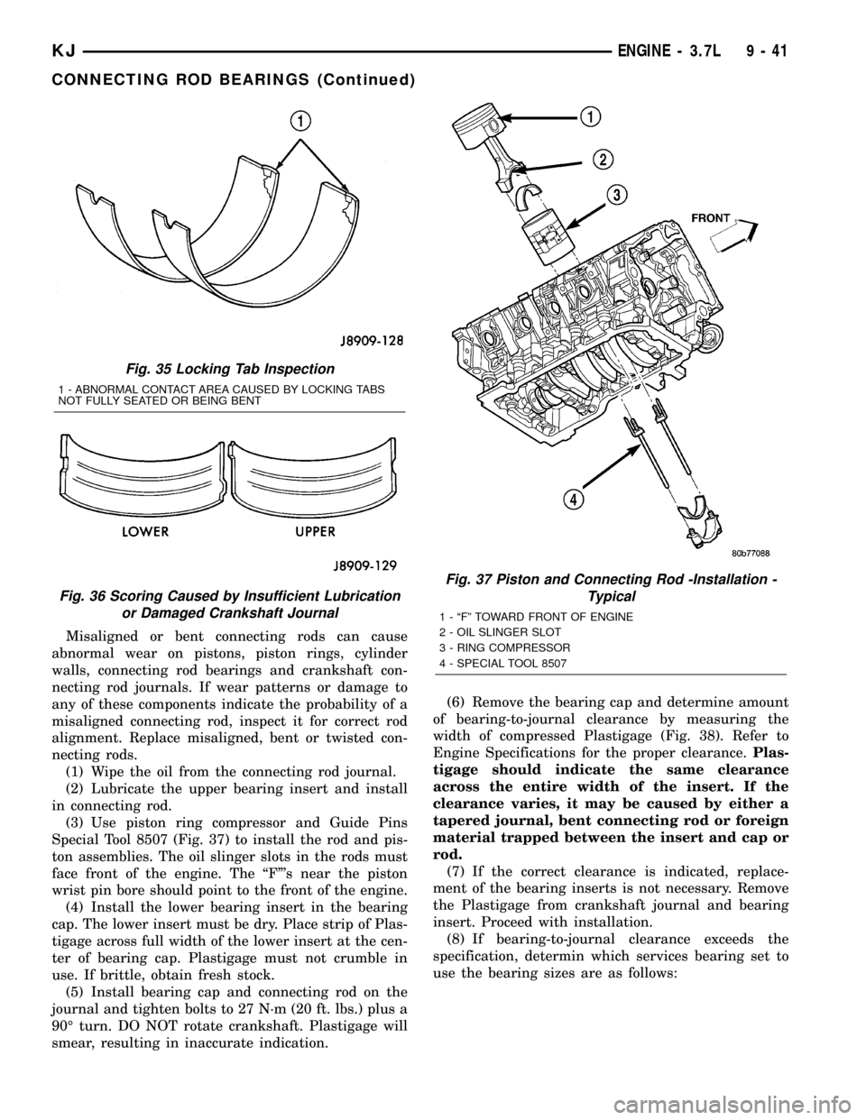
Misaligned or bent connecting rods can cause
abnormal wear on pistons, piston rings, cylinder
walls, connecting rod bearings and crankshaft con-
necting rod journals. If wear patterns or damage to
any of these components indicate the probability of a
misaligned connecting rod, inspect it for correct rod
alignment. Replace misaligned, bent or twisted con-
necting rods.
(1) Wipe the oil from the connecting rod journal.
(2) Lubricate the upper bearing insert and install
in connecting rod.
(3) Use piston ring compressor and Guide Pins
Special Tool 8507 (Fig. 37) to install the rod and pis-
ton assemblies. The oil slinger slots in the rods must
face front of the engine. The ªFº's near the piston
wrist pin bore should point to the front of the engine.
(4) Install the lower bearing insert in the bearing
cap. The lower insert must be dry. Place strip of Plas-
tigage across full width of the lower insert at the cen-
ter of bearing cap. Plastigage must not crumble in
use. If brittle, obtain fresh stock.
(5) Install bearing cap and connecting rod on the
journal and tighten bolts to 27 N´m (20 ft. lbs.) plus a
90É turn. DO NOT rotate crankshaft. Plastigage will
smear, resulting in inaccurate indication.(6) Remove the bearing cap and determine amount
of bearing-to-journal clearance by measuring the
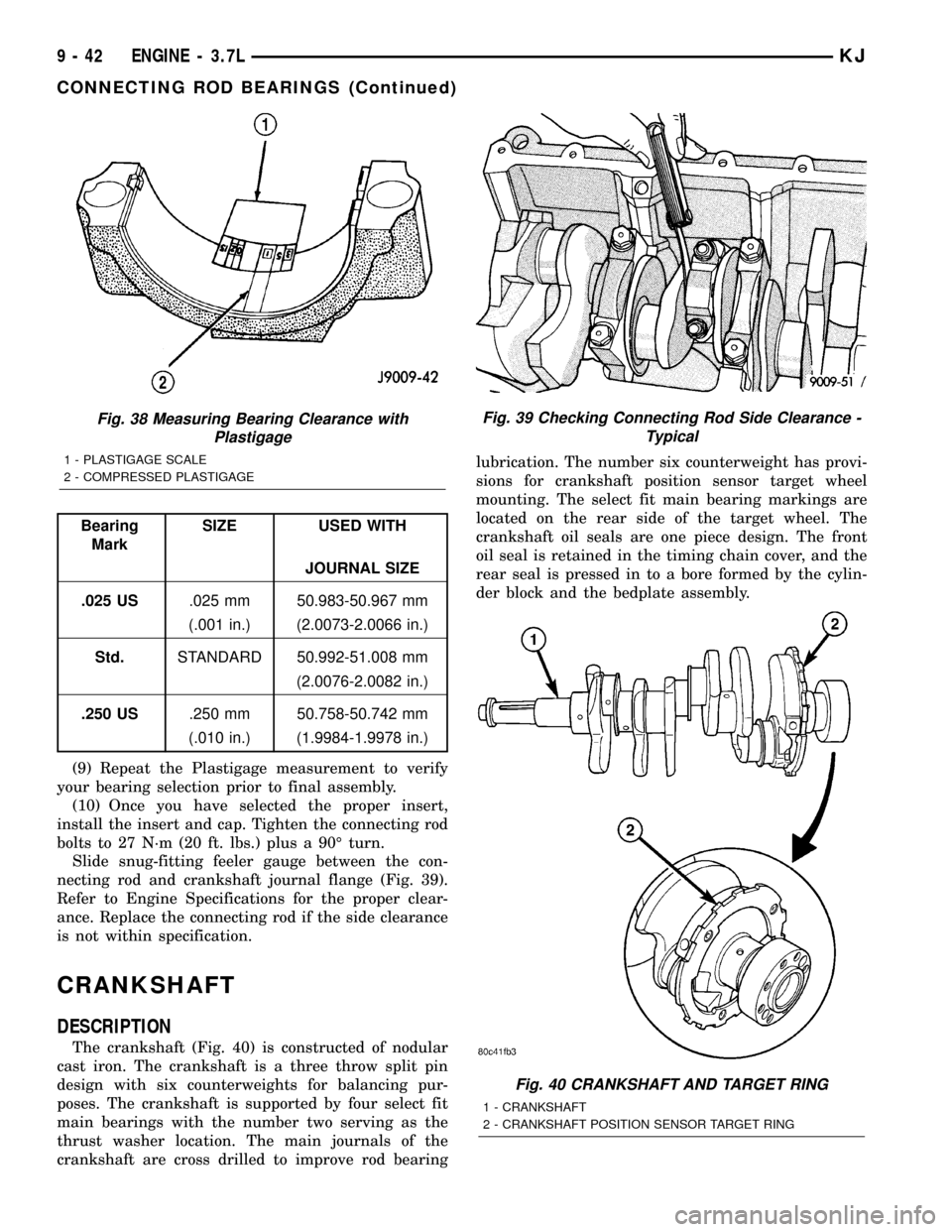
width of compressed Plastigage (Fig. 38). Refer to
Engine Specifications for the proper clearance.Plas-
tigage should indicate the same clearance
across the entire width of the insert. If the
clearance varies, it may be caused by either a
tapered journal, bent connecting rod or foreign
material trapped between the insert and cap or
rod.
(7) If the correct clearance is indicated, replace-
ment of the bearing inserts is not necessary. Remove
the Plastigage from crankshaft journal and bearing
insert. Proceed with installation.
(8) If bearing-to-journal clearance exceeds the
specification, determin which services bearing set to
use the bearing sizes are as follows:
Fig. 35 Locking Tab Inspection
1 - ABNORMAL CONTACT AREA CAUSED BY LOCKING TABS
NOT FULLY SEATED OR BEING BENT
Fig. 36 Scoring Caused by Insufficient Lubrication
or Damaged Crankshaft Journal
Fig. 37 Piston and Connecting Rod -Installation -
Typical
1 - ªFº TOWARD FRONT OF ENGINE
2 - OIL SLINGER SLOT
3 - RING COMPRESSOR
4 - SPECIAL TOOL 8507
KJENGINE - 3.7L 9 - 41
CONNECTING ROD BEARINGS (Continued)
Page 1257 of 1803
Bearing
MarkSIZE USED WITH
JOURNAL SIZE
.025 US.025 mm 50.983-50.967 mm
(.001 in.) (2.0073-2.0066 in.)
Std.STANDARD 50.992-51.008 mm
(2.0076-2.0082 in.)
.250 US.250 mm 50.758-50.742 mm
(.010 in.) (1.9984-1.9978 in.)
(9) Repeat the Plastigage measurement to verify
your bearing selection prior to final assembly.
(10) Once you have selected the proper insert,
install the insert and cap. Tighten the connecting rod
bolts to 27 N´m (20 ft. lbs.) plus a 90É turn.
Slide snug-fitting feeler gauge between the con-
necting rod and crankshaft journal flange (Fig. 39).
Refer to Engine Specifications for the proper clear-
ance. Replace the connecting rod if the side clearance
is not within specification.
CRANKSHAFT
DESCRIPTION
The crankshaft (Fig. 40) is constructed of nodular
cast iron. The crankshaft is a three throw split pin
design with six counterweights for balancing pur-
poses. The crankshaft is supported by four select fit
main bearings with the number two serving as the
thrust washer location. The main journals of the
crankshaft are cross drilled to improve rod bearinglubrication. The number six counterweight has provi-
sions for crankshaft position sensor target wheel
mounting. The select fit main bearing markings are
located on the rear side of the target wheel. The
crankshaft oil seals are one piece design. The front
oil seal is retained in the timing chain cover, and the
rear seal is pressed in to a bore formed by the cylin-
der block and the bedplate assembly.
Fig. 38 Measuring Bearing Clearance with
Plastigage
1 - PLASTIGAGE SCALE
2 - COMPRESSED PLASTIGAGE
Fig. 39 Checking Connecting Rod Side Clearance -
Typical
Fig. 40 CRANKSHAFT AND TARGET RING
1 - CRANKSHAFT
2 - CRANKSHAFT POSITION SENSOR TARGET RING
9 - 42 ENGINE - 3.7LKJ
CONNECTING ROD BEARINGS (Continued)
Page 1258 of 1803
REMOVAL
NOTE: To remove the crankshaft from the engine,
the engine must be removed from the vehicle.
(1) Remove the engine. Refer to Engine Assembly
in this section for procedure.
(2) Remove the engine oil pump. Refer to Oil
Pump in this section for procedure.
CAUTION: DO NOT pry on the oil pan gasket when
removing the oil pan, The oil pan gasket is mounted
to the cylinder block in three locations and will
remain attached to block when removing oil pan.
Gasket can not be removed with oil pan.
(3) Remove oil pan bolts and oil pan.
(4) Remove the oil pump pickup tube and oil pan
gasket /windage tray.
(5) Remove the bedplate mounting bolts. Note the
location of the two stud bolts for installation.
(6) Remove the connecting rods from the crank-
shaft.
CAUTION: The bedplate to cylinder block mating
surface is a critical sealing surface. Do not pry on
or damage this surface in anyway.
NOTE: The bedplate contains the lower main bear-
ing halves. Use care when handling bedplate as not
to drop or damage bearing halves. Installing main
bearing halves in the wrong position will cause
sever damage to the crankshaft.
NOTE: The bedplate has pry points cast into it. Use
these points only. The pry points are shown below.
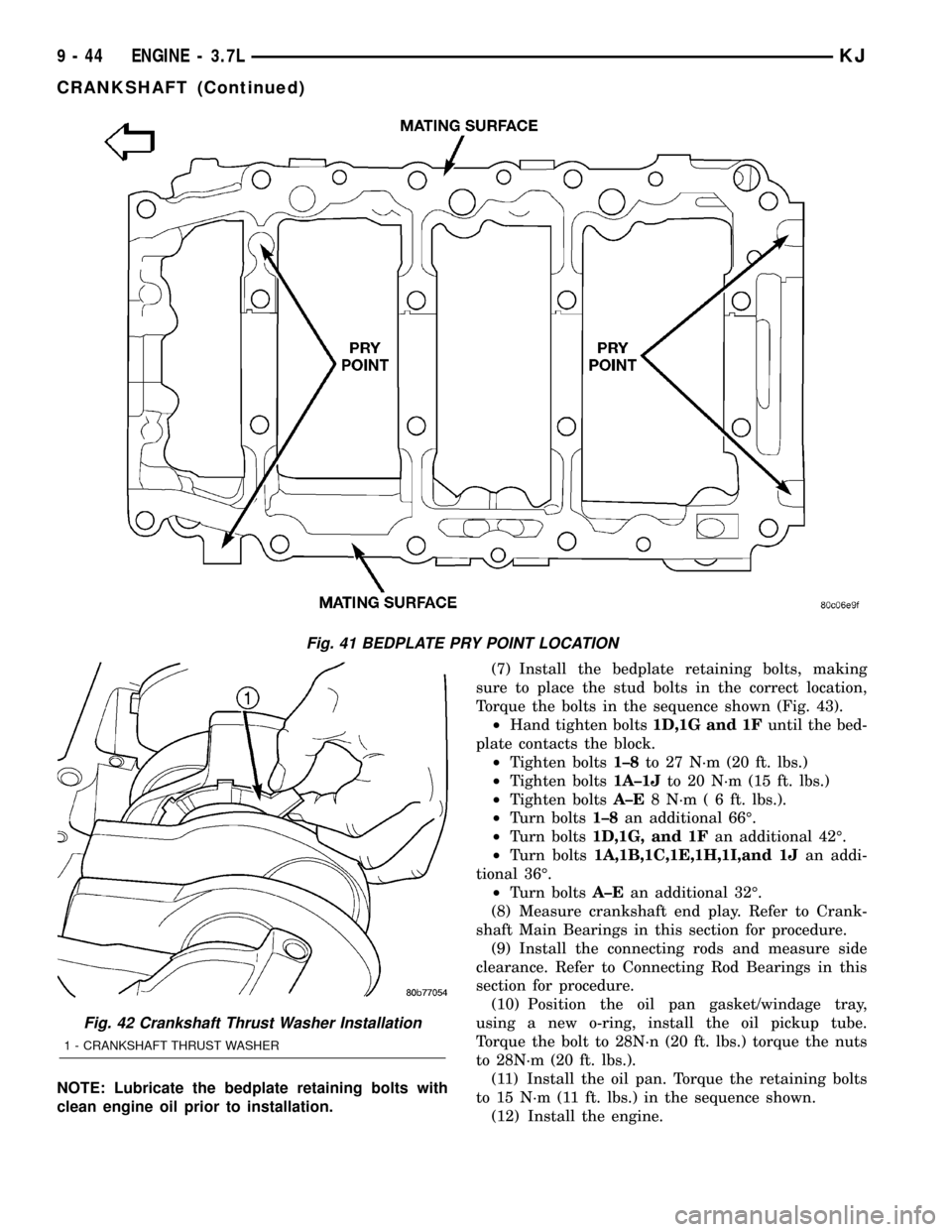
(7) Carefully pry on the pry points (Fig. 41) to
loosen the bedplate then remove the bedplate.
CAUTION: When removing the crankshaft, use care
not to damage bearing surfaces on the crankshaft.
(8) Remove the crankshaft.
(9) Remove the crankshaft tone wheel.
INSPECTION
NOTE: Thoroughly inspect the connecting rod bear-
ing bores and main bearing bores for scoring, blue-
ing or severe scratches. Further disassembly may
be required.
If connecting rod bearing bores show damage, the
cylinder heads must be removed to service the piston
and rod assemblies. If the bedplate or the cylinderblock main bearing bores show damage the engine
must be replaced.
(1) If required, remove the main bearing halves
from the cylinder block and bedplate.
(2) Thoroughly clean the bedplate to cylinder block
sealing surfaces and main bearing bores. Remove all
oil and sealant residue.
(3) Inspect the bedplate main bearing bores for
cracks, scoring or severe blueing. If either condition
exists the engine must be replaced.
(4) Inspect the crankshaft thrust washer for scor-
ing, scratches or blueing. If either condition exist
replace the thrust washer.
(5) Inspect the oil pan gasket/windage tray for
splits, tears or cracks in the gasket sealing surfaces.
Replace gasket as necessary.
INSTALLATION
CAUTION: Main bearings are select fit. Refer to
Crankshaft Main Bearings in this section for proper
bearing selections.
CAUTION: When installing crankshaft, use care not
to damage bearing surfaces on the crankshaft.
NOTE: Apply sealant to the tone wheel retaining
screws prior to installation.
(1) Lubricate upper main bearing halves with
clean engine oil.
(2) Install the crankshaft tone wheel. Torque the
mounting screws to 22 N´m (21 ft. lbs.).
(3) Position crankshaft in cylinder block.
(4) Install the thrust washers (Fig. 42).
CAUTION: The bedplate to cylinder block mating
surface must be coated with MoparTEngine RTV
sealant prior to installation. Failure to do so will
cause severe oil leaks.
NOTE: Make sure that the bedplate and cylinder
block sealing surfaces are clean and free of oil or
other contaminants. Contaminants on the sealing
surfaces may cause main bearing distortion and/or
oil leaks.
(5) Apply a 2.5mm (0.100 inch) bead of Mopart
Engine RTV sealant to the cylinder block-to-bedplate
mating surface as shown.
(6) Coat the crankshaft main bearing journals
with clean engine oil and position the bedplate onto
the cylinder block.
KJENGINE - 3.7L 9 - 43
CRANKSHAFT (Continued)
Page 1259 of 1803
NOTE: Lubricate the bedplate retaining bolts with
clean engine oil prior to installation.(7) Install the bedplate retaining bolts, making
sure to place the stud bolts in the correct location,
Torque the bolts in the sequence shown (Fig. 43).
²Hand tighten bolts1D,1G and 1Funtil the bed-
plate contacts the block.
²Tighten bolts1±8to 27 N´m (20 ft. lbs.)
²Tighten bolts1A±1Jto 20 N´m (15 ft. lbs.)
²Tighten boltsA±E8 N´m ( 6 ft. lbs.).
²Turn bolts1±8an additional 66É.
²Turn bolts1D,1G, and 1Fan additional 42É.
²Turn bolts1A,1B,1C,1E,1H,1I,and 1Jan addi-
tional 36É.
²Turn boltsA±Ean additional 32É.
(8) Measure crankshaft end play. Refer to Crank-
shaft Main Bearings in this section for procedure.
(9) Install the connecting rods and measure side
clearance. Refer to Connecting Rod Bearings in this
section for procedure.
(10) Position the oil pan gasket/windage tray,
using a new o-ring, install the oil pickup tube.
Torque the bolt to 28N´n (20 ft. lbs.) torque the nuts
to 28N´m (20 ft. lbs.).
(11) Install the oil pan. Torque the retaining bolts
to 15 N´m (11 ft. lbs.) in the sequence shown.
(12) Install the engine.
Fig. 41 BEDPLATE PRY POINT LOCATION
Fig. 42 Crankshaft Thrust Washer Installation
1 - CRANKSHAFT THRUST WASHER
9 - 44 ENGINE - 3.7LKJ
CRANKSHAFT (Continued)