2002 JEEP LIBERTY torque
[x] Cancel search: torquePage 1329 of 1803
INSPECTION
ENGINE BLOCK
(1) Clean cylinder block thoroughly and check all
core hole plugs for evidence of leaking.
(2) If new core plugs are to be installed, (Refer to 9
- ENGINE - STANDARD PROCEDURE - ENGINE
CORE AND OIL GALLERY PLUGS).
(3) Examine block and cylinder bores for cracks or
fractures.
(4) Check block deck surfaces for flatness. Deck
surface must be within service limit of 0.1 mm (0.004
in.).
CYLINDER BORE
NOTE: The cylinder bores should be measured at
normal room temperature, 21ÉC (70ÉF).
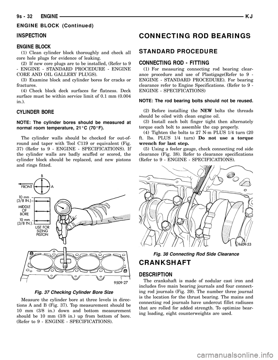
The cylinder walls should be checked for out-of-
round and taper with Tool C119 or equivalent (Fig.
37) (Refer to 9 - ENGINE - SPECIFICATIONS). If
the cylinder walls are badly scuffed or scored, the
cylinder block should be replaced, and new pistons
and rings fitted.
Measure the cylinder bore at three levels in direc-
tions A and B (Fig. 37). Top measurement should be
10 mm (3/8 in.) down and bottom measurement
should be 10 mm (3/8 in.) up from bottom of bore.
(Refer to 9 - ENGINE - SPECIFICATIONS).
CONNECTING ROD BEARINGS
STANDARD PROCEDURE
CONNECTING ROD - FITTING
(1) For measuring connecting rod bearing clear-
ance procedure and use of Plastigage(Refer to 9 -
ENGINE - STANDARD PROCEDURE). For bearing
clearance refer to Engine Specifications. (Refer to 9 -
ENGINE - SPECIFICATIONS)
NOTE: The rod bearing bolts should not be reused.
(2) Before installing theNEWbolts the threads
should be oiled with clean engine oil.
(3) Install each bolt finger tight then alternately
torque each bolt to assemble the cap properly.
(4) Tighten the bolts to 27 N´m PLUS 1/4 turn (20
ft. lbs. PLUS 1/4 turn)Do not use a torque
wrench for last step.
(5) Using a feeler gauge, check connecting rod side
clearance (Fig. 38). Refer to clearance specifications
(Refer to 9 - ENGINE - SPECIFICATIONS).
CRANKSHAFT
DESCRIPTION
The crankshaft is made of nodular cast iron and
includes five main bearing journals and four connect-
ing rod journals (Fig. 39). The number three journal
is the location for the thrust bearing. The mains and
connecting rod journals have undercut fillet radiuses
that are rolled for added strength. To optimize bear-
ing loading, eight counterweights are used.
Fig. 37 Checking Cylinder Bore Size
Fig. 38 Connecting Rod Side Clearance
9s - 32 ENGINEKJ
ENGINE BLOCK (Continued)
Page 1331 of 1803
INSPECTION
The crankshaft journals should be checked for
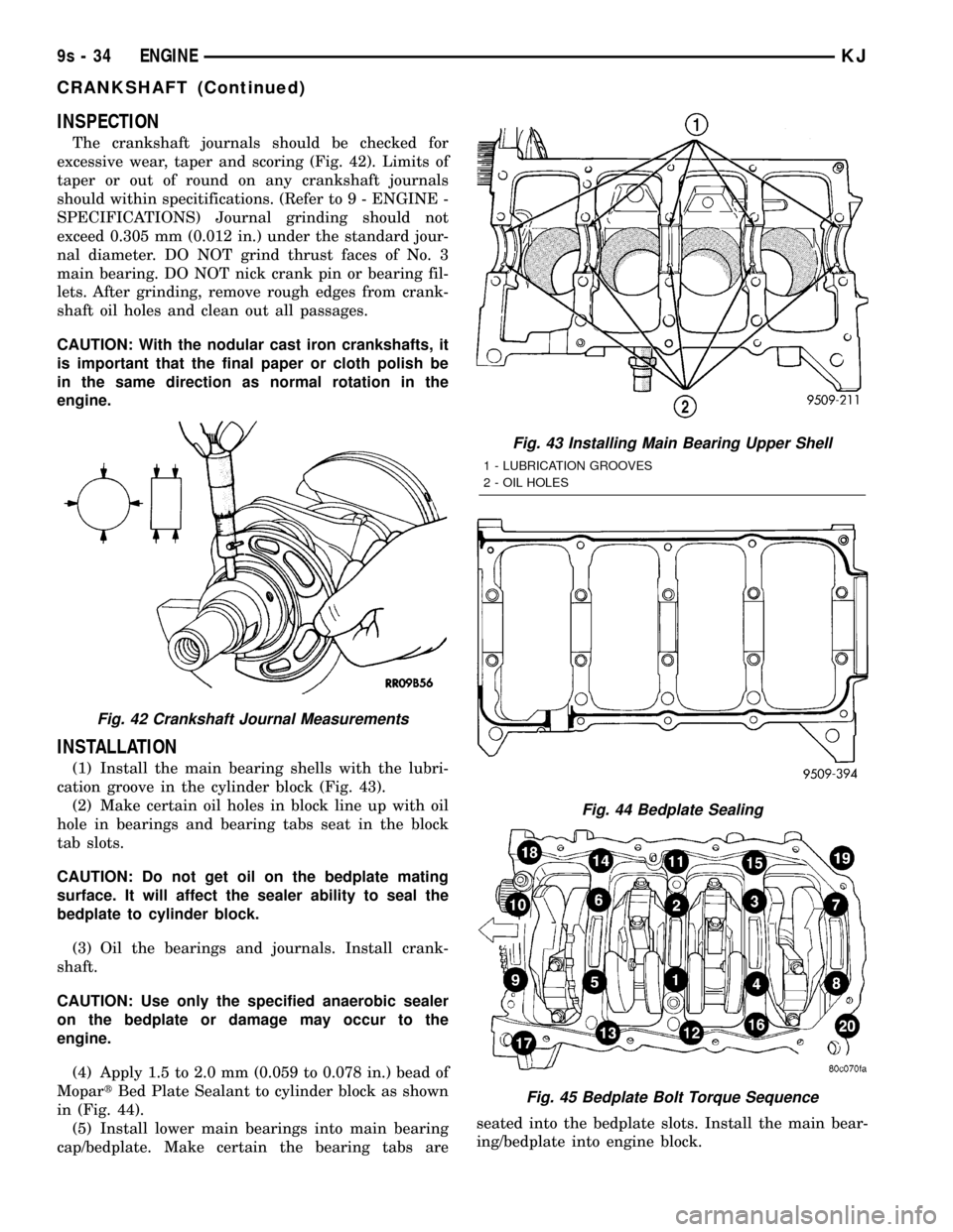
excessive wear, taper and scoring (Fig. 42). Limits of
taper or out of round on any crankshaft journals
should within specitifications. (Refer to 9 - ENGINE -
SPECIFICATIONS) Journal grinding should not
exceed 0.305 mm (0.012 in.) under the standard jour-
nal diameter. DO NOT grind thrust faces of No. 3
main bearing. DO NOT nick crank pin or bearing fil-
lets. After grinding, remove rough edges from crank-
shaft oil holes and clean out all passages.
CAUTION: With the nodular cast iron crankshafts, it
is important that the final paper or cloth polish be
in the same direction as normal rotation in the
engine.
INSTALLATION
(1) Install the main bearing shells with the lubri-
cation groove in the cylinder block (Fig. 43).
(2) Make certain oil holes in block line up with oil
hole in bearings and bearing tabs seat in the block
tab slots.
CAUTION: Do not get oil on the bedplate mating
surface. It will affect the sealer ability to seal the
bedplate to cylinder block.
(3) Oil the bearings and journals. Install crank-
shaft.
CAUTION: Use only the specified anaerobic sealer
on the bedplate or damage may occur to the
engine.
(4) Apply 1.5 to 2.0 mm (0.059 to 0.078 in.) bead of
MopartBed Plate Sealant to cylinder block as shown
in (Fig. 44).
(5) Install lower main bearings into main bearing
cap/bedplate. Make certain the bearing tabs areseated into the bedplate slots. Install the main bear-
ing/bedplate into engine block.
Fig. 42 Crankshaft Journal Measurements
Fig. 43 Installing Main Bearing Upper Shell
1 - LUBRICATION GROOVES
2 - OIL HOLES
Fig. 44 Bedplate Sealing
Fig. 45 Bedplate Bolt Torque Sequence
9s - 34 ENGINEKJ
CRANKSHAFT (Continued)
Page 1332 of 1803
(6) Before installing the bolts the threads should
be oiled with clean engine oil, wipe off any excess oil.
(7) Install main bearing bedplate to engine block
bolts 11, 17, and 20 finger tight. Tighten these bolts
down together until the bedplate contacts the cylin-
der block.
(8) To ensure correct thrust bearing alignment,
perform the following steps:
²Step 1: Rotate crankshaft until number 4 piston
is at TDC.
²Step 2: Move crankshaft rearward to limits of
travel.
²Step 3: Then, move crankshaft forward to limits
of travel.
²Step 4: Wedge an appropriate tool between the
rear of the cylinder block(NOT BED PLATE)and
the rear crankshaft counterweight. This will hold the
crankshaft in it's furthest forward position.
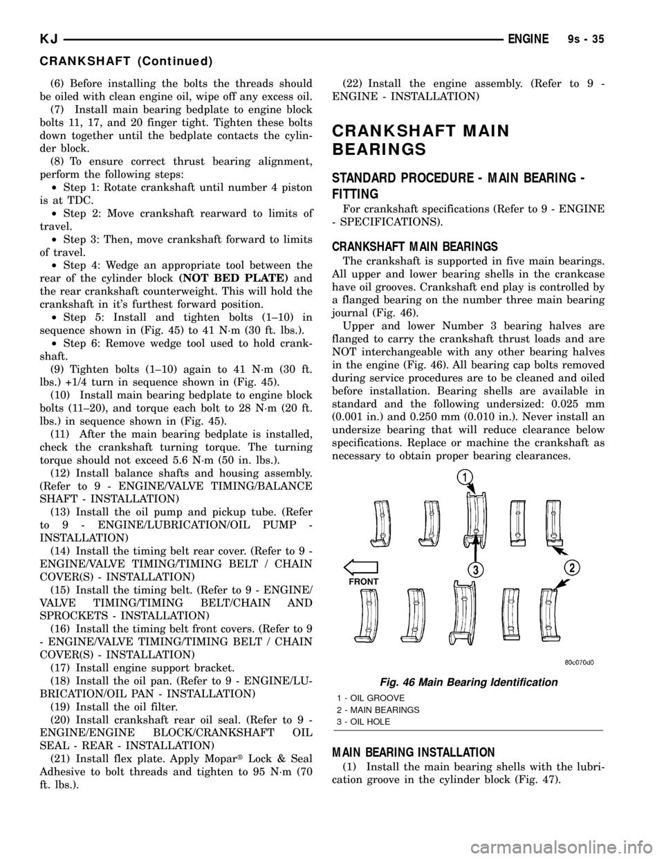
²Step 5: Install and tighten bolts (1±10) in
sequence shown in (Fig. 45) to 41 N´m (30 ft. lbs.).
²Step 6: Remove wedge tool used to hold crank-
shaft.
(9) Tighten bolts (1±10) again to 41 N´m (30 ft.
lbs.) +1/4 turn in sequence shown in (Fig. 45).
(10) Install main bearing bedplate to engine block
bolts (11±20), and torque each bolt to 28 N´m (20 ft.
lbs.) in sequence shown in (Fig. 45).
(11) After the main bearing bedplate is installed,
check the crankshaft turning torque. The turning
torque should not exceed 5.6 N´m (50 in. lbs.).
(12) Install balance shafts and housing assembly.
(Refer to 9 - ENGINE/VALVE TIMING/BALANCE
SHAFT - INSTALLATION)
(13) Install the oil pump and pickup tube. (Refer
to 9 - ENGINE/LUBRICATION/OIL PUMP -
INSTALLATION)
(14) Install the timing belt rear cover. (Refer to 9 -
ENGINE/VALVE TIMING/TIMING BELT / CHAIN
COVER(S) - INSTALLATION)
(15) Install the timing belt. (Refer to 9 - ENGINE/
VALVE TIMING/TIMING BELT/CHAIN AND
SPROCKETS - INSTALLATION)
(16) Install the timing belt front covers. (Refer to 9
- ENGINE/VALVE TIMING/TIMING BELT / CHAIN
COVER(S) - INSTALLATION)
(17) Install engine support bracket.
(18) Install the oil pan. (Refer to 9 - ENGINE/LU-
BRICATION/OIL PAN - INSTALLATION)
(19) Install the oil filter.
(20) Install crankshaft rear oil seal. (Refer to 9 -
ENGINE/ENGINE BLOCK/CRANKSHAFT OIL
SEAL - REAR - INSTALLATION)
(21) Install flex plate. Apply MopartLock & Seal
Adhesive to bolt threads and tighten to 95 N´m (70
ft. lbs.).(22) Install the engine assembly. (Refer to 9 -
ENGINE - INSTALLATION)
CRANKSHAFT MAIN
BEARINGS
STANDARD PROCEDURE - MAIN BEARING -
FITTING
For crankshaft specifications (Refer to 9 - ENGINE
- SPECIFICATIONS).
CRANKSHAFT MAIN BEARINGS
The crankshaft is supported in five main bearings.
All upper and lower bearing shells in the crankcase
have oil grooves. Crankshaft end play is controlled by
a flanged bearing on the number three main bearing
journal (Fig. 46).
Upper and lower Number 3 bearing halves are
flanged to carry the crankshaft thrust loads and are
NOT interchangeable with any other bearing halves
in the engine (Fig. 46). All bearing cap bolts removed
during service procedures are to be cleaned and oiled
before installation. Bearing shells are available in
standard and the following undersized: 0.025 mm
(0.001 in.) and 0.250 mm (0.010 in.). Never install an
undersize bearing that will reduce clearance below
specifications. Replace or machine the crankshaft as
necessary to obtain proper bearing clearances.
MAIN BEARING INSTALLATION
(1) Install the main bearing shells with the lubri-
cation groove in the cylinder block (Fig. 47).
Fig. 46 Main Bearing Identification
1 - OIL GROOVE
2 - MAIN BEARINGS
3 - OIL HOLE
KJENGINE9s-35
CRANKSHAFT (Continued)
Page 1333 of 1803
(2) Make certain oil holes in block line up with oil
holes in bearings. Bearing tabs must seat in the
block tab slots.
CAUTION: Do not get oil on the bedplate mating
surface. It will may effect the sealer ability to seal
the bedplate to cylinder block.
(3) Oil the bearings and journals and install
crankshaft.
CAUTION: Use only the specified anaerobic sealer
on the bedplate or damage may occur to the
engine. Ensure that both cylinder block and bed-
plate surfaces are clean.
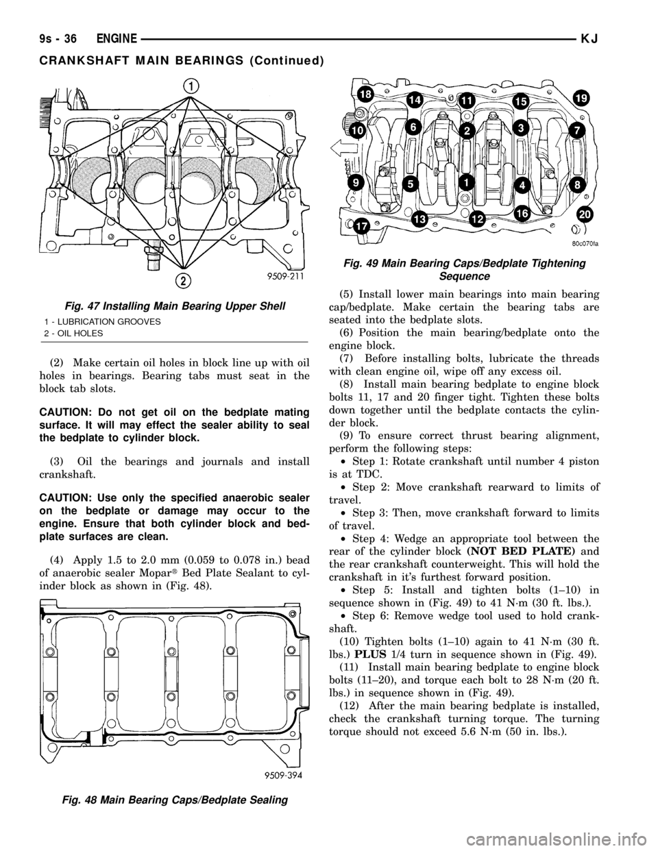
(4) Apply 1.5 to 2.0 mm (0.059 to 0.078 in.) bead
of anaerobic sealer MopartBed Plate Sealant to cyl-
inder block as shown in (Fig. 48).(5) Install lower main bearings into main bearing
cap/bedplate. Make certain the bearing tabs are
seated into the bedplate slots.
(6) Position the main bearing/bedplate onto the
engine block.
(7) Before installing bolts, lubricate the threads
with clean engine oil, wipe off any excess oil.
(8) Install main bearing bedplate to engine block
bolts 11, 17 and 20 finger tight. Tighten these bolts
down together until the bedplate contacts the cylin-
der block.
(9) To ensure correct thrust bearing alignment,
perform the following steps:
²Step 1: Rotate crankshaft until number 4 piston
is at TDC.
²Step 2: Move crankshaft rearward to limits of
travel.
²Step 3: Then, move crankshaft forward to limits
of travel.
²Step 4: Wedge an appropriate tool between the
rear of the cylinder block(NOT BED PLATE)and
the rear crankshaft counterweight. This will hold the
crankshaft in it's furthest forward position.
²Step 5: Install and tighten bolts (1±10) in
sequence shown in (Fig. 49) to 41 N´m (30 ft. lbs.).
²Step 6: Remove wedge tool used to hold crank-
shaft.
(10) Tighten bolts (1±10) again to 41 N´m (30 ft.
lbs.)PLUS1/4 turn in sequence shown in (Fig. 49).
(11) Install main bearing bedplate to engine block
bolts (11±20), and torque each bolt to 28 N´m (20 ft.
lbs.) in sequence shown in (Fig. 49).
(12) After the main bearing bedplate is installed,
check the crankshaft turning torque. The turning
torque should not exceed 5.6 N´m (50 in. lbs.).
Fig. 47 Installing Main Bearing Upper Shell
1 - LUBRICATION GROOVES
2 - OIL HOLES
Fig. 48 Main Bearing Caps/Bedplate Sealing
Fig. 49 Main Bearing Caps/Bedplate Tightening
Sequence
9s - 36 ENGINEKJ
CRANKSHAFT MAIN BEARINGS (Continued)
Page 1338 of 1803
INSTALLATION
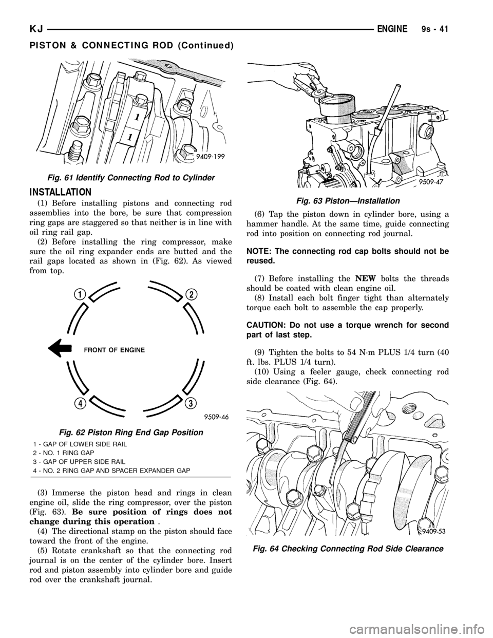
(1) Before installing pistons and connecting rod
assemblies into the bore, be sure that compression
ring gaps are staggered so that neither is in line with
oil ring rail gap.
(2) Before installing the ring compressor, make
sure the oil ring expander ends are butted and the
rail gaps located as shown in (Fig. 62). As viewed
from top.
(3) Immerse the piston head and rings in clean
engine oil, slide the ring compressor, over the piston
(Fig. 63).Be sure position of rings does not
change during this operation.
(4) The directional stamp on the piston should face
toward the front of the engine.
(5) Rotate crankshaft so that the connecting rod
journal is on the center of the cylinder bore. Insert
rod and piston assembly into cylinder bore and guide
rod over the crankshaft journal.(6) Tap the piston down in cylinder bore, using a
hammer handle. At the same time, guide connecting
rod into position on connecting rod journal.
NOTE: The connecting rod cap bolts should not be
reused.
(7) Before installing theNEWbolts the threads
should be coated with clean engine oil.
(8) Install each bolt finger tight than alternately
torque each bolt to assemble the cap properly.
CAUTION: Do not use a torque wrench for second
part of last step.
(9) Tighten the bolts to 54 N´m PLUS 1/4 turn (40
ft. lbs. PLUS 1/4 turn).
(10) Using a feeler gauge, check connecting rod
side clearance (Fig. 64).
Fig. 61 Identify Connecting Rod to Cylinder
Fig. 62 Piston Ring End Gap Position
1 - GAP OF LOWER SIDE RAIL
2 - NO. 1 RING GAP
3 - GAP OF UPPER SIDE RAIL
4 - NO. 2 RING GAP AND SPACER EXPANDER GAP
Fig. 63 PistonÐInstallation
Fig. 64 Checking Connecting Rod Side Clearance
KJENGINE9s-41
PISTON & CONNECTING ROD (Continued)
Page 1341 of 1803
STRUCTURAL COLLAR
REMOVAL
(1) Raise vehicle on hoist.
(2) Remove structural collar attaching bolts.
(3) Remove collar.
INSTALLATION
CAUTION: Torque procedure for the structural collar
must be followed or damage could occur to oil pan
and collar.
(1) Perform the following steps for installing struc-
tural collar.
²Step 1: Position collar between transmission and
oil pan. Install collar to transmission bolts,hand
start only.
²Step 2: Install collar to oil pan bolts,hand snug
only.
²Step 3: Tighten collar to transmission bolts.
²Step 4: Tighten collar to oil pan bolts.
(2) Lower vehicle.
ENGINE MOUNTING
DESCRIPTION
The engine mounting system consist of three
mounts; right and a left side support the powertrain,
and rear mount to control powertrain torque. The
mounts are of molded rubber material.
FRONT MOUNT
REMOVAL
(1) Raise vehicle on hoist.
(2) Remove the front engine mount through bolt
from the insulator.
(3) Remove the engine front mount bolts and
remove the insulator assembly.
(4) Remove the front mounting bracket from
engine, if necessary.
INSTALLATION
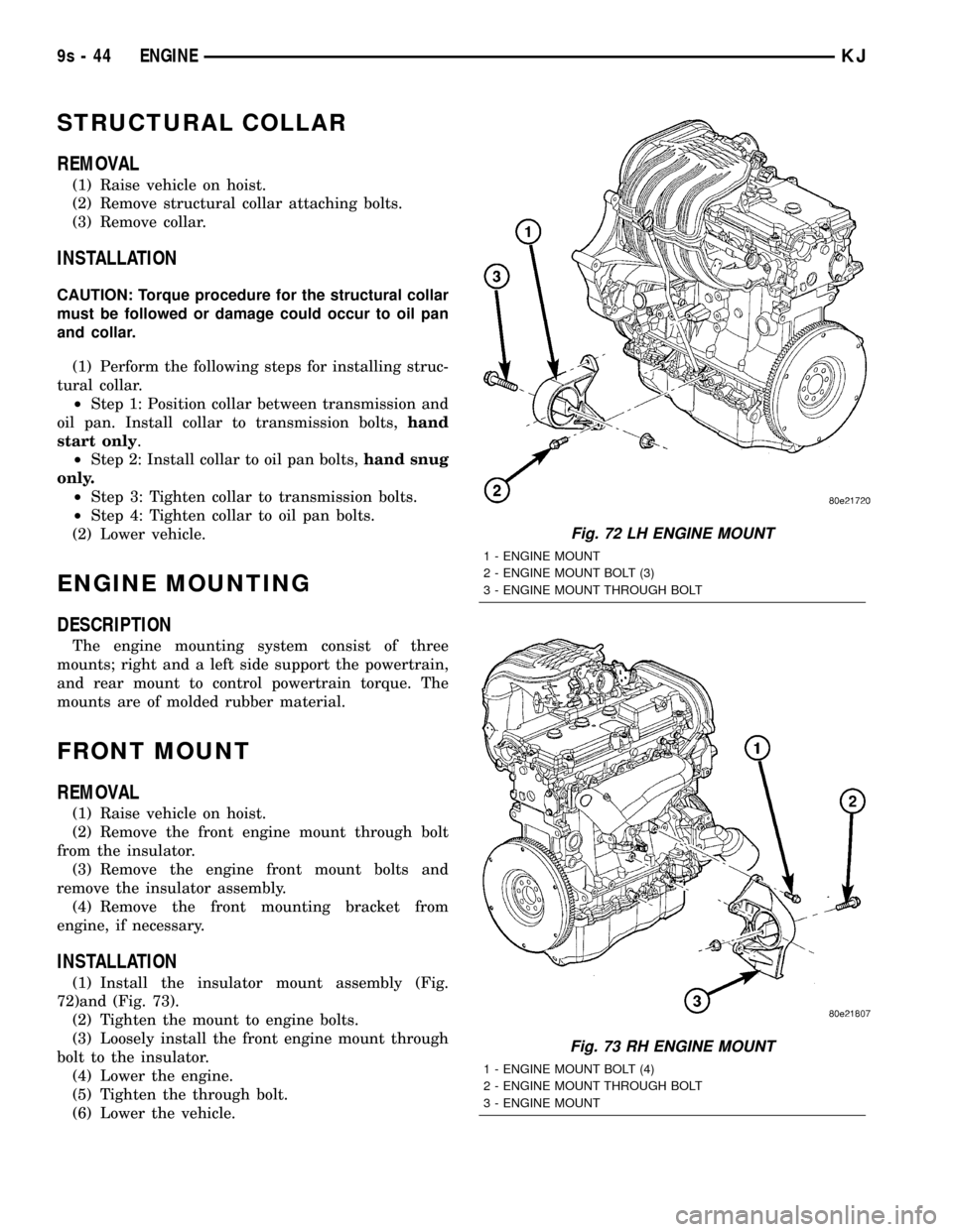
(1) Install the insulator mount assembly (Fig.
72)and (Fig. 73).
(2) Tighten the mount to engine bolts.
(3) Loosely install the front engine mount through
bolt to the insulator.
(4) Lower the engine.
(5) Tighten the through bolt.
(6) Lower the vehicle.
Fig. 72 LH ENGINE MOUNT
1 - ENGINE MOUNT
2 - ENGINE MOUNT BOLT (3)
3 - ENGINE MOUNT THROUGH BOLT
Fig. 73 RH ENGINE MOUNT
1 - ENGINE MOUNT BOLT (4)
2 - ENGINE MOUNT THROUGH BOLT
3 - ENGINE MOUNT
9s - 44 ENGINEKJ
Page 1342 of 1803
REAR MOUNT
REMOVAL
NOTE: A resilient rubber cushion supports the
transmission at the rear between the transmission
extension housing and the rear support crossmem-
ber or skid plate.
(1) Disconnect negative cable from battery.
(2) Raise the vehicle and support the transmission.
(3) Remove the nuts holding the support cushion
to the crossmember. Remove the crossmember.
MANUAL TRANSMISSION
a. Remove the support cushion nuts and remove
the cushion.
b. Remove the transmission support bracket bolts
and remove the bracket from the transmission.
AUTOMATIC TRANSMISSION
c. Remove the support cushion bolts and remove
the cushion and the support bracket from the trans-
mission (4WD) or from the adaptor bracket (2WD).
d. On 2WD vehicles, remove the bolts holding the
transmission support adaptor bracket to the trans-
mission. Remove the adaptor bracket.
INSTALLATION
MANUAL TRANSMISSION:
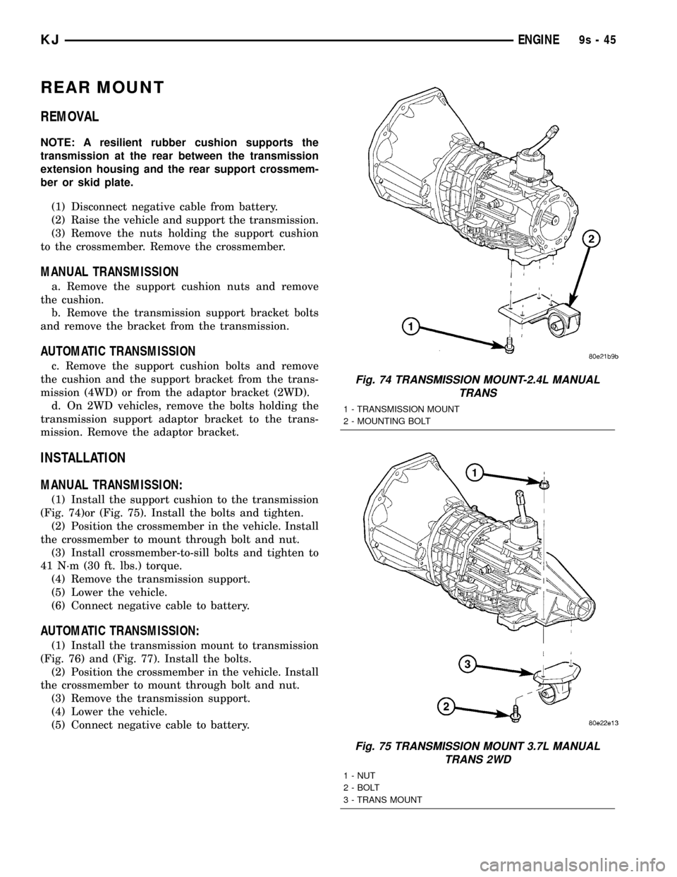
(1) Install the support cushion to the transmission
(Fig. 74)or (Fig. 75). Install the bolts and tighten.
(2) Position the crossmember in the vehicle. Install
the crossmember to mount through bolt and nut.
(3) Install crossmember-to-sill bolts and tighten to
41 N´m (30 ft. lbs.) torque.
(4) Remove the transmission support.
(5) Lower the vehicle.
(6) Connect negative cable to battery.
AUTOMATIC TRANSMISSION:
(1) Install the transmission mount to transmission
(Fig. 76) and (Fig. 77). Install the bolts.
(2) Position the crossmember in the vehicle. Install
the crossmember to mount through bolt and nut.
(3) Remove the transmission support.
(4) Lower the vehicle.
(5) Connect negative cable to battery.
Fig. 74 TRANSMISSION MOUNT-2.4L MANUAL
TRANS
1 - TRANSMISSION MOUNT
2 - MOUNTING BOLT
Fig. 75 TRANSMISSION MOUNT 3.7L MANUAL
TRANS 2WD
1 - NUT
2 - BOLT
3 - TRANS MOUNT
KJENGINE9s-45
Page 1348 of 1803
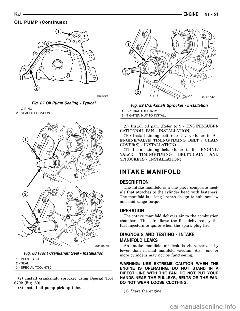
(7) Install crankshaft sprocket using Special Tool
6792 (Fig. 89).
(8) Install oil pump pick-up tube.(9) Install oil pan. (Refer to 9 - ENGINE/LUBRI-
CATION/OIL PAN - INSTALLATION)
(10) Install timing belt rear cover. (Refer to 9 -
ENGINE/VALVE TIMING/TIMING BELT / CHAIN
COVER(S) - INSTALLATION)
(11) Install timing belt. (Refer to 9 - ENGINE/
VALVE TIMING/TIMING BELT/CHAIN AND
SPROCKETS - INSTALLATION)
INTAKE MANIFOLD
DESCRIPTION
The intake manifold is a one piece composite mod-
ule that attaches to the cylinder head with fasteners.
The manifold is a long branch design to enhance low
and mid-range torque
OPERATION
The intake manifold delivers air to the combustion
chambers. This air allows the fuel delivered by the
fuel injectors to ignite when the spark plug fire.
DIAGNOSIS AND TESTING - INTAKE
MANIFOLD LEAKS
An intake manifold air leak is characterized by
lower than normal manifold vacuum. Also, one or
more cylinders may not be functioning.
WARNING: USE EXTREME CAUTION WHEN THE
ENGINE IS OPERATING. DO NOT STAND IN A
DIRECT LINE WITH THE FAN. DO NOT PUT YOUR
HANDS NEAR THE PULLEYS, BELTS OR THE FAN.
DO NOT WEAR LOOSE CLOTHING.
(1) Start the engine.
Fig. 87 Oil Pump Sealing - Typical
1 - O-RING
2 - SEALER LOCATION
Fig. 88 Front Crankshaft Seal - Installation
1 - PROTECTOR
2 - SEAL
3 - SPECIAL TOOL 6780
Fig. 89 Crankshaft Sprocket - Installation
1 - SPECIAL TOOL 6792
2 - TIGHTEN NUT TO INSTALL
KJENGINE9s-51
OIL PUMP (Continued)