2002 JEEP LIBERTY tire size
[x] Cancel search: tire sizePage 570 of 1803
INSTALLATION
CAUTION: Always use the correct bulb size and
type for replacement. An incorrect bulb size or type
may overheat and cause damage to the lamp, the
socket and/or the lamp wiring.
NORTH AMERICA
(1) Align the base of the bulb with the receptacle
in the license plate lamp unit socket.
(2) Push the bulb straight into the license plate
lamp unit socket until it is firmly seated.
(3) Reach through the opening in the rear bumper
fascia between the license plate and the lamp to
align the socket and bulb with the socket opening on
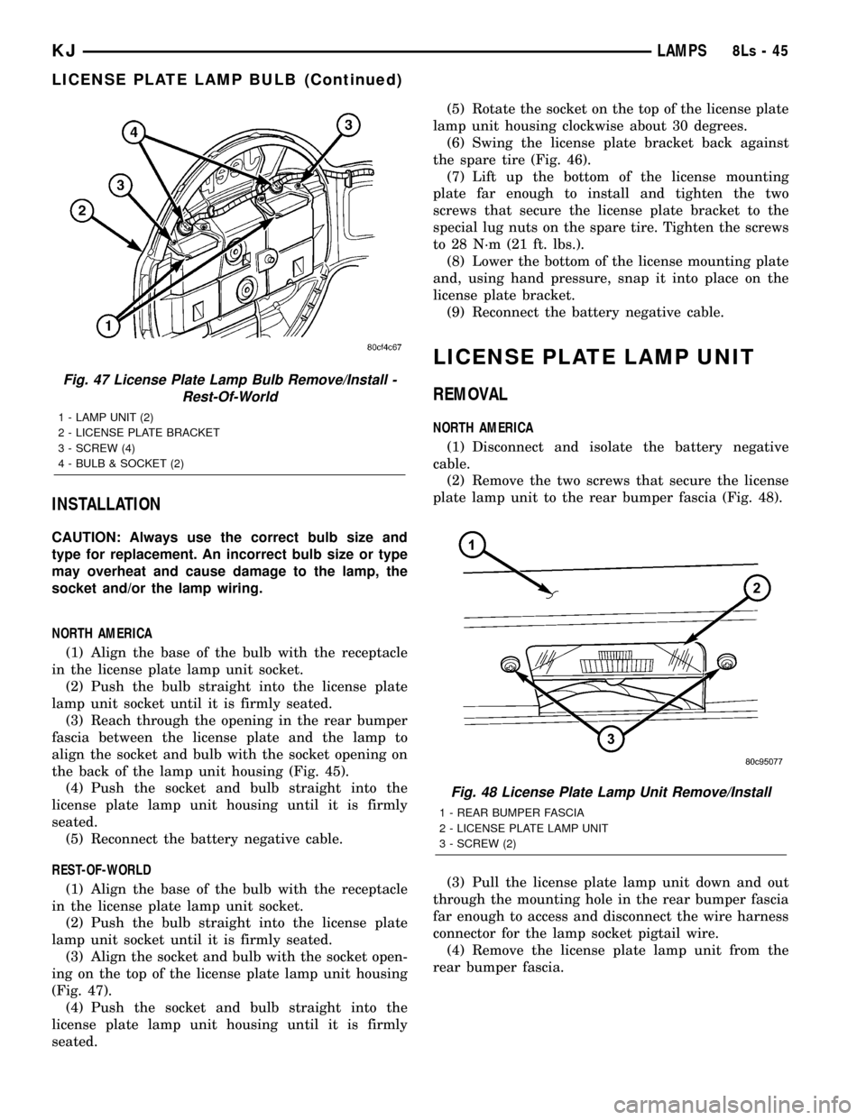
the back of the lamp unit housing (Fig. 45).
(4) Push the socket and bulb straight into the
license plate lamp unit housing until it is firmly
seated.
(5) Reconnect the battery negative cable.
REST-OF-WORLD
(1) Align the base of the bulb with the receptacle
in the license plate lamp unit socket.
(2) Push the bulb straight into the license plate
lamp unit socket until it is firmly seated.
(3) Align the socket and bulb with the socket open-
ing on the top of the license plate lamp unit housing
(Fig. 47).
(4) Push the socket and bulb straight into the
license plate lamp unit housing until it is firmly
seated.(5) Rotate the socket on the top of the license plate
lamp unit housing clockwise about 30 degrees.
(6) Swing the license plate bracket back against
the spare tire (Fig. 46).
(7) Lift up the bottom of the license mounting
plate far enough to install and tighten the two
screws that secure the license plate bracket to the
special lug nuts on the spare tire. Tighten the screws
to 28 N´m (21 ft. lbs.).
(8) Lower the bottom of the license mounting plate
and, using hand pressure, snap it into place on the
license plate bracket.
(9) Reconnect the battery negative cable.
LICENSE PLATE LAMP UNIT
REMOVAL
NORTH AMERICA
(1) Disconnect and isolate the battery negative
cable.
(2) Remove the two screws that secure the license
plate lamp unit to the rear bumper fascia (Fig. 48).
(3) Pull the license plate lamp unit down and out
through the mounting hole in the rear bumper fascia
far enough to access and disconnect the wire harness
connector for the lamp socket pigtail wire.
(4) Remove the license plate lamp unit from the
rear bumper fascia.
Fig. 47 License Plate Lamp Bulb Remove/Install -
Rest-Of-World
1 - LAMP UNIT (2)
2 - LICENSE PLATE BRACKET
3 - SCREW (4)
4 - BULB & SOCKET (2)
Fig. 48 License Plate Lamp Unit Remove/Install
1 - REAR BUMPER FASCIA
2 - LICENSE PLATE LAMP UNIT
3 - SCREW (2)
KJLAMPS8Ls-45
LICENSE PLATE LAMP BULB (Continued)
Page 739 of 1803

A wiper arm cannot be adjusted or repaired. If
damaged or faulty, the entire wiper arm unit must be
replaced.
OPERATION
The rear wiper arm is designed to mechanically
transmit the motion from the rear wiper motor out-
put shaft to the rear wiper blade. The wiper arm
must be properly indexed to the motor output shaft
in order to maintain the proper wiper blade travel on
the glass. The wiper arm support is designed to lift
and support the rear wiper arm and blade off of the
glass when the rear wiper blade is parked. This sup-
port and the park ramp on the tailgate outer panel
below the glass also provide an alignment reference
to ensure accurate rear wiper arm and blade instal-
lation. The tapered hole in the wiper arm pivot end
is interlocks with the serrations on the outer circum-
ference of the tapered motor output shaft, allowing
positive engagement and finite adjustment of this
connection. A hex nut secures the wiper arm pivot
end to the threads on the rear wiper motor output
shaft and the pivot cover hinges and snaps over this
connection for a neat appearance. The spring-loaded
wiper arm hinge controls the down-force applied
through the tip of the wiper arm to the wiper blade
on the glass. The hook formation on the tip of the
wiper arm provides a cradle for securing and latching
the wiper blade pivot block to the wiper arm.
REMOVAL
(1) Lift the rear wiper arm pivot cover by lifting it
at the rear wiper motor output shaft end of the arm
(Fig. 9).
(2) Remove the nut that secures the rear wiper
arm to the rear wiper motor output shaft.
(3) If necessary, use a battery terminal puller to
disengage the wiper arm from the rear wiper motor
output shaft splines (Fig. 10).
NOTE: Depending upon the size and type of puller
used, it may be necessary to remove the spare tire
from the tailgate. Refer to the owner's manual in the
vehicle glove box for information on removing the
spare tire from the tailgate.
(4) Remove the rear wiper arm pivot end from the
motor output shaft.
INSTALLATION
NOTE: Always install the wiper arm and blade with
the wiper motor in the Park position.
(1) The rear wiper arm must be indexed to the
motor output shaft with the rear wiper motor in the
park position to be properly installed. Place thewiper arm onto the tailgate with the wiper arm sup-
port positioned on the park ramp and the tapered
mounting hole on the pivot end of the arm positioned
over the rear wiper motor output shaft.
(2) Position the tab on the back of the rear wiper
arm support on the tailgate park ramp in the Instal-
lation Position (Fig. 11).
(3) With the wiper arm in the Installation Posi-
tion, push the tapered mounting hole on the pivot
end of the wiper arm down over the rear wiper motor
output shaft.
Fig. 9 Rear Wiper Arm Remove/Install
1 - SPARE TIRE
2 - WRENCH
3 - FLIP-UP GLASS
4 - PARK RAMP
5 - REAR WIPER ARM
6 - PIVOT COVER
Fig. 10 Wiper Arm Puller - Typical
1 - WIPER ARM
2 - WIPER PIVOT
3 - BATTERY TERMINAL PULLER
8R - 38 REAR WIPERS/WASHERSKJ
REAR WIPER ARM (Continued)
Page 1256 of 1803
Misaligned or bent connecting rods can cause
abnormal wear on pistons, piston rings, cylinder
walls, connecting rod bearings and crankshaft con-
necting rod journals. If wear patterns or damage to
any of these components indicate the probability of a
misaligned connecting rod, inspect it for correct rod
alignment. Replace misaligned, bent or twisted con-
necting rods.
(1) Wipe the oil from the connecting rod journal.
(2) Lubricate the upper bearing insert and install
in connecting rod.
(3) Use piston ring compressor and Guide Pins
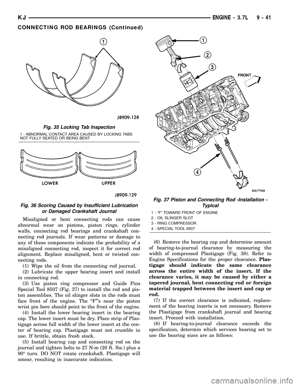
Special Tool 8507 (Fig. 37) to install the rod and pis-
ton assemblies. The oil slinger slots in the rods must
face front of the engine. The ªFº's near the piston
wrist pin bore should point to the front of the engine.
(4) Install the lower bearing insert in the bearing
cap. The lower insert must be dry. Place strip of Plas-
tigage across full width of the lower insert at the cen-
ter of bearing cap. Plastigage must not crumble in
use. If brittle, obtain fresh stock.
(5) Install bearing cap and connecting rod on the
journal and tighten bolts to 27 N´m (20 ft. lbs.) plus a
90É turn. DO NOT rotate crankshaft. Plastigage will
smear, resulting in inaccurate indication.(6) Remove the bearing cap and determine amount
of bearing-to-journal clearance by measuring the
width of compressed Plastigage (Fig. 38). Refer to
Engine Specifications for the proper clearance.Plas-
tigage should indicate the same clearance
across the entire width of the insert. If the
clearance varies, it may be caused by either a
tapered journal, bent connecting rod or foreign
material trapped between the insert and cap or
rod.
(7) If the correct clearance is indicated, replace-
ment of the bearing inserts is not necessary. Remove
the Plastigage from crankshaft journal and bearing
insert. Proceed with installation.
(8) If bearing-to-journal clearance exceeds the
specification, determin which services bearing set to
use the bearing sizes are as follows:
Fig. 35 Locking Tab Inspection
1 - ABNORMAL CONTACT AREA CAUSED BY LOCKING TABS
NOT FULLY SEATED OR BEING BENT
Fig. 36 Scoring Caused by Insufficient Lubrication
or Damaged Crankshaft Journal
Fig. 37 Piston and Connecting Rod -Installation -
Typical
1 - ªFº TOWARD FRONT OF ENGINE
2 - OIL SLINGER SLOT
3 - RING COMPRESSOR
4 - SPECIAL TOOL 8507
KJENGINE - 3.7L 9 - 41
CONNECTING ROD BEARINGS (Continued)
Page 1265 of 1803
90É turn. DO NOT rotate crankshaft. Plastigage will
smear, resulting in inaccurate indication.
(6) Remove the bearing cap and determine amount
of bearing-to-journal clearance by measuring the
width of compressed Plastigage. Refer to Engine
Specifications for the proper clearance.Plastigage
should indicate the same clearance across the
entire width of the insert. If the clearance var-
ies, it may be caused by either a tapered jour-
nal, bent connecting rod or foreign material
trapped between the insert and cap or rod.
(7) If the correct clearance is indicated, replace-
ment of the bearing inserts is not necessary. Remove
the Plastigage from crankshaft journal and bearing
insert. Proceed with installation.
(8) If bearing-to-journal clearance exceeds the
specification, determin which services bearing set to
use the bearing sizes are as follows:
Bearing
MarkSIZE USED WITH
JOURNAL SIZE
.025 US.025 mm 57.871-57.879 mm
(.001 in.) (2.2783-2.2786 in.)
Std.STANDARD 57.896-57.904 mm
(2.2793-2.2810 in.)
.250 US.250 mm 57.646-57.654 mm
(.010 in.) (2.2695-2.2698 in.)
(9) Repeat the Plastigage measurement to verify
your bearing selection prior to final assembly.
(10) Once you have selected the proper insert,
install the insert and cap. Tighten the connecting rod
bolts to 27 N´m (20 ft. lbs.) plus a 90É turn.
Slide snug-fitting feeler gauge between the con-
necting rod and crankshaft journal flange. Refer to
Engine Specifications for the proper clearance.
Replace the connecting rod if the side clearance is
not within specification.
STANDARD PROCEDURE - PISTON FITTING
(1) To correctly select the proper size piston, a cyl-
inder bore gauge, capable of reading in 0.003 mm (
.0001 in.) INCREMENTS is required. If a bore gauge
is not available, do not use an inside micrometer.
(2) Measure the inside diameter of the cylinder
bore at a point 38.0 mm (1.5 inches) below top of
bore. Start perpendicular (across or at 90 degrees) to
the axis of the crankshaft at point A and then take
an additional bore reading 90 degrees to that at point
B (Fig. 54).
(3) The coated pistons will be serviced with the
piston pin and connecting rod pre-assembled.(4) The coating material is applied to the piston
after the final piston machining process. Measuring
the outside diameter of a coated piston will not pro-
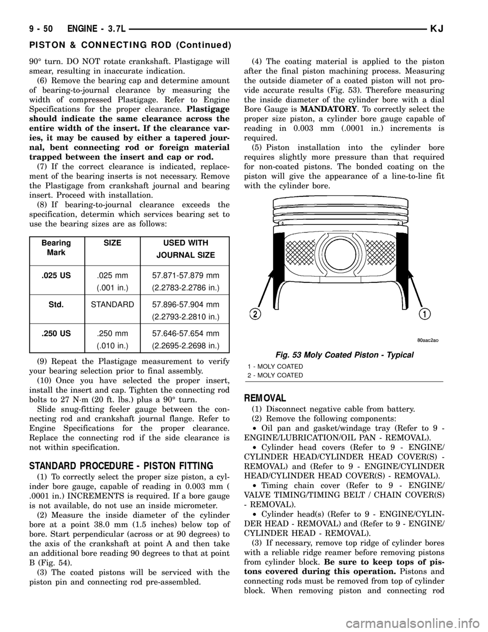
vide accurate results (Fig. 53). Therefore measuring
the inside diameter of the cylinder bore with a dial
Bore Gauge isMANDATORY. To correctly select the
proper size piston, a cylinder bore gauge capable of
reading in 0.003 mm (.0001 in.) increments is
required.
(5) Piston installation into the cylinder bore
requires slightly more pressure than that required
for non-coated pistons. The bonded coating on the
piston will give the appearance of a line-to-line fit
with the cylinder bore.
REMOVAL
(1) Disconnect negative cable from battery.
(2) Remove the following components:
²Oil pan and gasket/windage tray (Refer to 9 -
ENGINE/LUBRICATION/OIL PAN - REMOVAL).
²Cylinder head covers (Refer to 9 - ENGINE/
CYLINDER HEAD/CYLINDER HEAD COVER(S) -
REMOVAL) and (Refer to 9 - ENGINE/CYLINDER
HEAD/CYLINDER HEAD COVER(S) - REMOVAL).
²Timing chain cover (Refer to 9 - ENGINE/
VALVE TIMING/TIMING BELT / CHAIN COVER(S)
- REMOVAL).
²Cylinder head(s) (Refer to 9 - ENGINE/CYLIN-
DER HEAD - REMOVAL) and (Refer to 9 - ENGINE/
CYLINDER HEAD - REMOVAL).
(3) If necessary, remove top ridge of cylinder bores
with a reliable ridge reamer before removing pistons
from cylinder block.Be sure to keep tops of pis-
tons covered during this operation.Pistons and
connecting rods must be removed from top of cylinder
block. When removing piston and connecting rod
Fig. 53 Moly Coated Piston - Typical
1 - MOLY COATED
2 - MOLY COATED
9 - 50 ENGINE - 3.7LKJ
PISTON & CONNECTING ROD (Continued)
Page 1432 of 1803
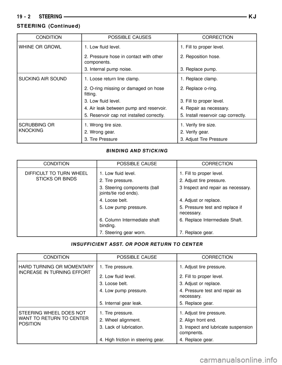
CONDITION POSSIBLE CAUSES CORRECTION
WHINE OR GROWL 1. Low fluid level. 1. Fill to proper level.
2. Pressure hose in contact with other
components.2. Reposition hose.
3. Internal pump noise. 3. Replace pump.
SUCKING AIR SOUND 1. Loose return line clamp. 1. Replace clamp.
2. O-ring missing or damaged on hose
fitting.2. Replace o-ring.
3. Low fluid level. 3. Fill to proper level.
4. Air leak between pump and reservoir. 4. Repair as necessary.
5. Reservoir cap not installed correctly. 5. Install reservoir cap correctly.
SCRUBBING OR
KNOCKING1. Wrong tire size. 1. Verify tire size.
2. Wrong gear. 2. Verify gear.
3. Tire Pressure 3. Adjust Tire Pressure
BINDING AND STICKING
CONDITION POSSIBLE CAUSE CORRECTION
DIFFICULT TO TURN WHEEL
STICKS OR BINDS1. Low fluid level. 1. Fill to proper level.
2. Tire pressure. 2. Adjust tire pressure.
3. Steering components (ball
joints/tie rod ends).3 Inspect and repair as necessary.
4. Loose belt. 4. Adjust or replace.
5. Low pump pressure. 5. Pressure test and replace if
necessary.
6. Column Intermediate shaft
binding.6. Replace Intermediate Shaft.
7. Steering gear worn. 7. Replace gear.
INSUFFICIENT ASST. OR POOR RETURN TO CENTER
CONDITION POSSIBLE CAUSE CORRECTION
HARD TURNING OR MOMENTARY
INCREASE IN TURNING EFFORT1. Tire pressure. 1. Adjust tire pressure.
2. Low fluid level. 2. Fill to proper level.
3. Loose belt. 3. Adjust or replace.
4. Low pump pressure. 4. Pressure test and repair as
necessary.
5. Internal gear leak. 5. Replace gear.
STEERING WHEEL DOES NOT
WANT TO RETURN TO CENTER
POSITION1. Tire pressure. 1. Adjust tire pressure.
2. Wheel alignment. 2. Align front end.
3. Lack of lubrication. 3. Inspect and lubricate suspension
compnents.
4. High friction in steering gear. 4. Replace gear.
19 - 2 STEERINGKJ
STEERING (Continued)
Page 1460 of 1803
TIRES
DESCRIPTION
DESCRIPTION - TIRES
Tires are designed and engineered for each specific
vehicle. They provide the best overall performance
for normal operation. The ride and handling charac-
teristics match the vehicle's requirements. With
proper care they will give excellent reliability, trac-
tion, skid resistance, and tread life.
Driving habits have more effect on tire life than
any other factor. Careful drivers will obtain in most
cases, much greater mileage than severe use or care-
less drivers. A few of the driving habits which will
shorten the life of any tire are:
²Rapid acceleration
²Severe brake applications
²High speed driving
²Excessive speeds on turns
²Striking curbs and other obstacles
Radial-ply tires are more prone to irregular tread
wear. It is important to follow the tire rotation inter-
val,(Refer to 22 - TIRES/WHEELS - STANDARD
PROCEDURE). This will help to achieve a greater
tread life.
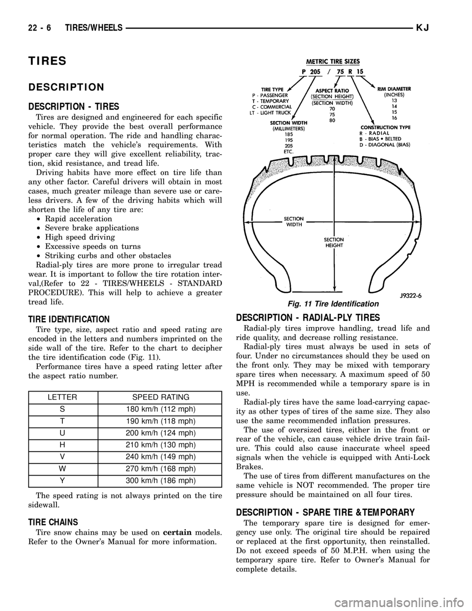
TIRE IDENTIFICATION
Tire type, size, aspect ratio and speed rating are
encoded in the letters and numbers imprinted on the
side wall of the tire. Refer to the chart to decipher
the tire identification code (Fig. 11).
Performance tires have a speed rating letter after
the aspect ratio number.
LETTER SPEED RATING
S 180 km/h (112 mph)
T 190 km/h (118 mph)
U 200 km/h (124 mph)
H 210 km/h (130 mph)
V 240 km/h (149 mph)
W 270 km/h (168 mph)
Y 300 km/h (186 mph)
The speed rating is not always printed on the tire
sidewall.
TIRE CHAINS
Tire snow chains may be used oncertainmodels.
Refer to the Owner's Manual for more information.
DESCRIPTION - RADIAL-PLY TIRES
Radial-ply tires improve handling, tread life and
ride quality, and decrease rolling resistance.
Radial-ply tires must always be used in sets of
four. Under no circumstances should they be used on
the front only. They may be mixed with temporary
spare tires when necessary. A maximum speed of 50
MPH is recommended while a temporary spare is in
use.
Radial-ply tires have the same load-carrying capac-
ity as other types of tires of the same size. They also
use the same recommended inflation pressures.
The use of oversized tires, either in the front or
rear of the vehicle, can cause vehicle drive train fail-
ure. This could also cause inaccurate wheel speed
signals when the vehicle is equipped with Anti-Lock
Brakes.
The use of tires from different manufactures on the
same vehicle is NOT recommended. The proper tire
pressure should be maintained on all four tires.
DESCRIPTION - SPARE TIRE &TEMPORARY
The temporary spare tire is designed for emer-
gency use only. The original tire should be repaired
or replaced at the first opportunity, then reinstalled.
Do not exceed speeds of 50 M.P.H. when using the
temporary spare tire. Refer to Owner's Manual for
complete details.
Fig. 11 Tire Identification
22 - 6 TIRES/WHEELSKJ
Page 1461 of 1803
DESCRIPTION - REPLACEMENT TIRES
The original equipment tires provide a proper bal-
ance of many characteristics such as:
²Ride
²Noise
²Handling
²Durability
²Tread life
²Traction
²Rolling resistance
²Speed capability
It is recommended that tires equivalent to the orig-
inal equipment tires be used when replacement is
needed.
Failure to use equivalent replacement tires may
adversely affect the safety and handling of the vehi-
cle.
The use of oversize tires may cause interference
with vehicle components. Under extremes of suspen-
sion and steering travel, interference with vehicle
components may cause tire damage.
WARNING: FAILURE TO EQUIP THE VEHICLE WITH
TIRES HAVING ADEQUATE SPEED CAPABILITY
CAN RESULT IN SUDDEN TIRE FAILURE.
DIAGNOSIS AND TESTING
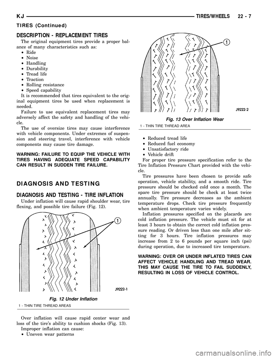
DIAGNOSIS AND TESTING - TIRE INFLATION
Under inflation will cause rapid shoulder wear, tire
flexing, and possible tire failure (Fig. 12).
Over inflation will cause rapid center wear and
loss of the tire's ability to cushion shocks (Fig. 13).
Improper inflation can cause:
²Uneven wear patterns²Reduced tread life
²Reduced fuel economy
²Unsatisfactory ride
²Vehicle drift
For proper tire pressure specification refer to the
Tire Inflation Pressure Chart provided with the vehi-
cle.
Tire pressures have been chosen to provide safe
operation, vehicle stability, and a smooth ride. Tire
pressure should be checked cold once a month. The
spare tire pressure should be check at least twice
annually. Tire pressure decreases as the ambient
temperature drops. Check tire pressure frequently
when ambient temperature varies widely.
Inflation pressures specified on the placards are
cold inflation pressure. The vehicle must sit for at
least 3 hours to obtain the correct cold inflation pres-
sure reading. Or driven less than one mile after sit-
ting for 3 hours. Tire inflation pressures may
increase from 2 to 6 pounds per square inch (psi)
during operation, due to increased tire temperature.
WARNING: OVER OR UNDER INFLATED TIRES CAN
AFFECT VEHICLE HANDLING AND TREAD WEAR.
THIS MAY CAUSE THE TIRE TO FAIL SUDDENLY,
RESULTING IN LOSS OF VEHICLE CONTROL.
Fig. 12 Under Inflation
1 - THIN TIRE THREAD AREAS
Fig. 13 Over Inflation Wear
1 - THIN TIRE THREAD AREA
KJTIRES/WHEELS 22 - 7
TIRES (Continued)
Page 1463 of 1803
INSTALLATION
(1) Install the spare tire onto the studs on the car-
rier.
(2) Install the two lug nuts and one wheel lock (if
equipped). Tighten the nuts to 115 N´m (85 ft.lbs.)
(3) Close the plastic wheel cover and install the
two mounting bolts. Tighten the nuts to 115 N´m (85
ft.lbs.)
(4) Close the license plate to cover the bolts and
latch.
WHEELS
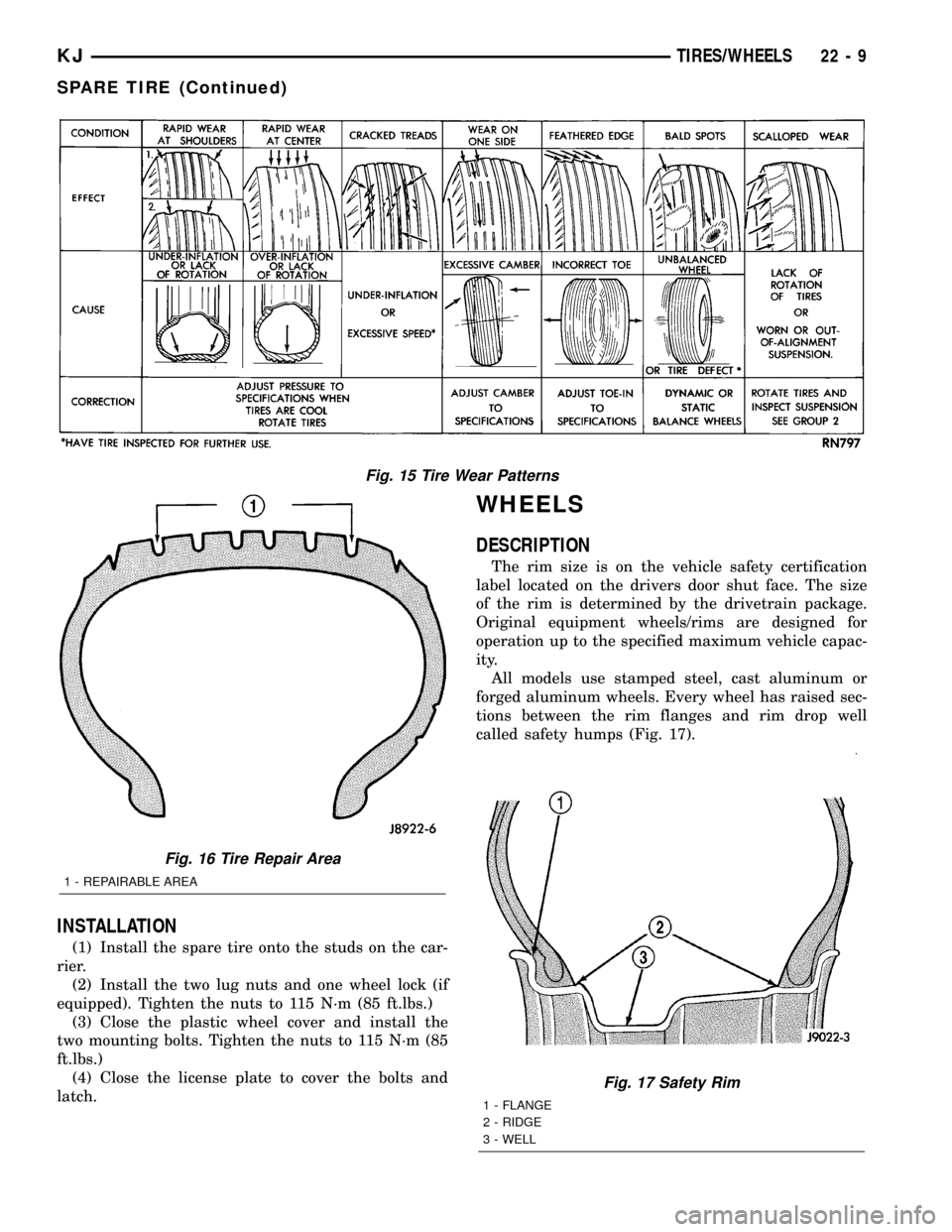
DESCRIPTION
The rim size is on the vehicle safety certification
label located on the drivers door shut face. The size
of the rim is determined by the drivetrain package.
Original equipment wheels/rims are designed for
operation up to the specified maximum vehicle capac-
ity.
All models use stamped steel, cast aluminum or
forged aluminum wheels. Every wheel has raised sec-
tions between the rim flanges and rim drop well
called safety humps (Fig. 17).
Fig. 15 Tire Wear Patterns
Fig. 16 Tire Repair Area
1 - REPAIRABLE AREA
Fig. 17 Safety Rim
1 - FLANGE
2 - RIDGE
3 - WELL
KJTIRES/WHEELS 22 - 9
SPARE TIRE (Continued)