2002 JEEP LIBERTY piston location
[x] Cancel search: piston locationPage 1258 of 1803
REMOVAL
NOTE: To remove the crankshaft from the engine,
the engine must be removed from the vehicle.
(1) Remove the engine. Refer to Engine Assembly
in this section for procedure.
(2) Remove the engine oil pump. Refer to Oil
Pump in this section for procedure.
CAUTION: DO NOT pry on the oil pan gasket when
removing the oil pan, The oil pan gasket is mounted
to the cylinder block in three locations and will
remain attached to block when removing oil pan.
Gasket can not be removed with oil pan.
(3) Remove oil pan bolts and oil pan.
(4) Remove the oil pump pickup tube and oil pan
gasket /windage tray.
(5) Remove the bedplate mounting bolts. Note the
location of the two stud bolts for installation.
(6) Remove the connecting rods from the crank-
shaft.
CAUTION: The bedplate to cylinder block mating
surface is a critical sealing surface. Do not pry on
or damage this surface in anyway.
NOTE: The bedplate contains the lower main bear-
ing halves. Use care when handling bedplate as not
to drop or damage bearing halves. Installing main
bearing halves in the wrong position will cause
sever damage to the crankshaft.
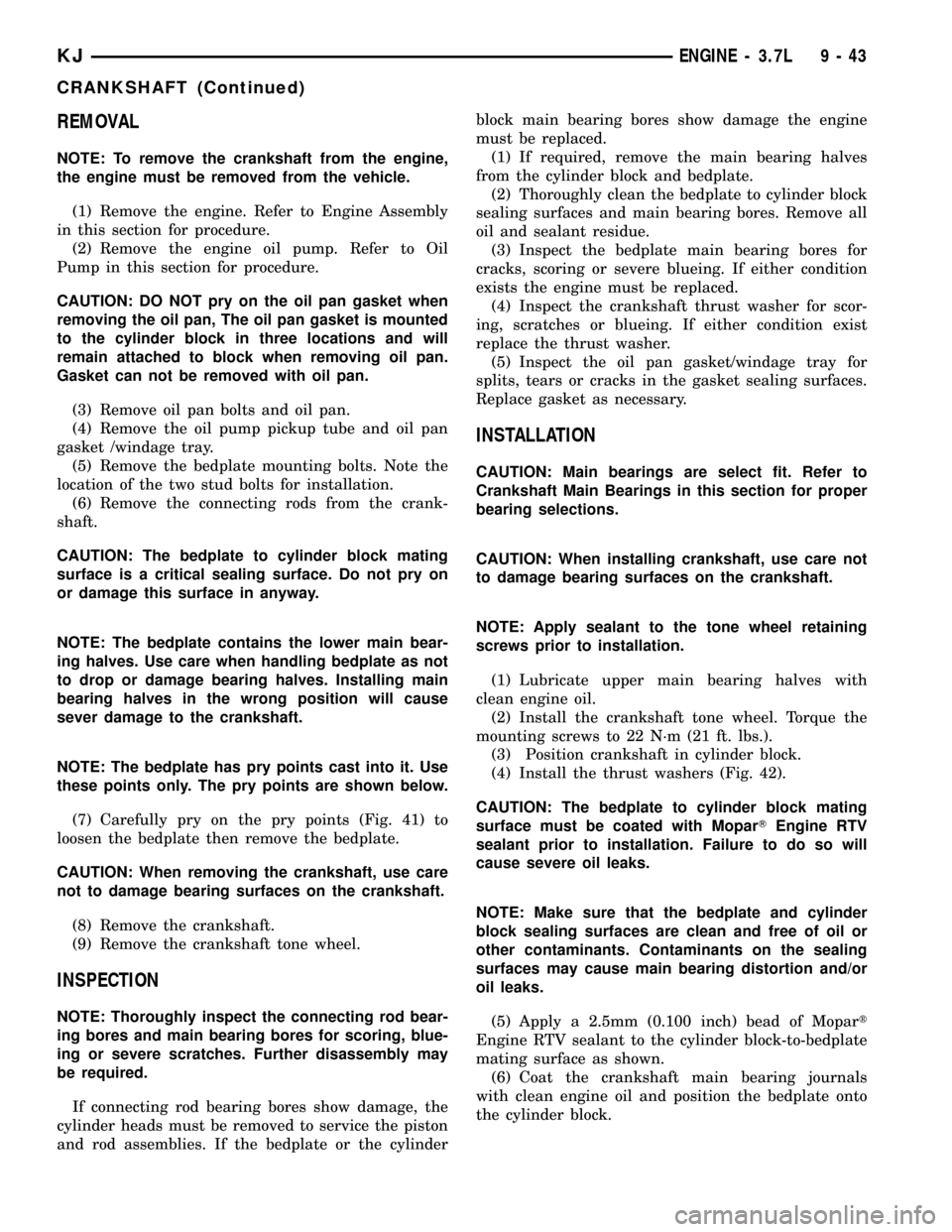
NOTE: The bedplate has pry points cast into it. Use
these points only. The pry points are shown below.
(7) Carefully pry on the pry points (Fig. 41) to
loosen the bedplate then remove the bedplate.
CAUTION: When removing the crankshaft, use care
not to damage bearing surfaces on the crankshaft.
(8) Remove the crankshaft.
(9) Remove the crankshaft tone wheel.
INSPECTION
NOTE: Thoroughly inspect the connecting rod bear-
ing bores and main bearing bores for scoring, blue-
ing or severe scratches. Further disassembly may
be required.
If connecting rod bearing bores show damage, the
cylinder heads must be removed to service the piston
and rod assemblies. If the bedplate or the cylinderblock main bearing bores show damage the engine
must be replaced.
(1) If required, remove the main bearing halves
from the cylinder block and bedplate.
(2) Thoroughly clean the bedplate to cylinder block
sealing surfaces and main bearing bores. Remove all
oil and sealant residue.
(3) Inspect the bedplate main bearing bores for
cracks, scoring or severe blueing. If either condition
exists the engine must be replaced.
(4) Inspect the crankshaft thrust washer for scor-
ing, scratches or blueing. If either condition exist
replace the thrust washer.
(5) Inspect the oil pan gasket/windage tray for
splits, tears or cracks in the gasket sealing surfaces.
Replace gasket as necessary.
INSTALLATION
CAUTION: Main bearings are select fit. Refer to
Crankshaft Main Bearings in this section for proper
bearing selections.
CAUTION: When installing crankshaft, use care not
to damage bearing surfaces on the crankshaft.
NOTE: Apply sealant to the tone wheel retaining
screws prior to installation.
(1) Lubricate upper main bearing halves with
clean engine oil.
(2) Install the crankshaft tone wheel. Torque the
mounting screws to 22 N´m (21 ft. lbs.).
(3) Position crankshaft in cylinder block.
(4) Install the thrust washers (Fig. 42).
CAUTION: The bedplate to cylinder block mating
surface must be coated with MoparTEngine RTV
sealant prior to installation. Failure to do so will
cause severe oil leaks.
NOTE: Make sure that the bedplate and cylinder
block sealing surfaces are clean and free of oil or
other contaminants. Contaminants on the sealing
surfaces may cause main bearing distortion and/or
oil leaks.
(5) Apply a 2.5mm (0.100 inch) bead of Mopart
Engine RTV sealant to the cylinder block-to-bedplate
mating surface as shown.
(6) Coat the crankshaft main bearing journals
with clean engine oil and position the bedplate onto
the cylinder block.
KJENGINE - 3.7L 9 - 43
CRANKSHAFT (Continued)
Page 1287 of 1803
(2) To determine if the secondary timing chains
are worn, rotate the engine clockwise until maximum
tensioner piston extension is obtained. Measure the
distance between the secondary timing chain ten-
sioner housing and the step ledge on the piston. The
measurement at point (A) must be less than 15mm
(.5906 inches).
(3) If the measurement exceeds the specification
the secondary timing chains are worn and require
replacement. Refer to Timing Chain and Sprockets in
this section for procedure.
SERVICE PROCEDURES
TIMING VERIFICATION
CAUTION: The 3.7L is a non free-wheeling design
engine. Therefore, correct engine timing is critical.
NOTE: Components referred to as left hand or right
hand are as viewed from the drivers position inside
the vehicle.
NOTE: The blue link plates on the chains and the
dots on the camshaft drive sprockets may not line
up during the timing verification procedure. The
blue link plates are lined up with the sprocket dots
only when re-timing the complete timing drive.
Once the timing drive is rotated blue link-to-dot
alignment is no longer valid.
Engine base timing can be verified by the following
procedure:
(1) Remove the cylinder head covers. Refer to the
procedure in this section.
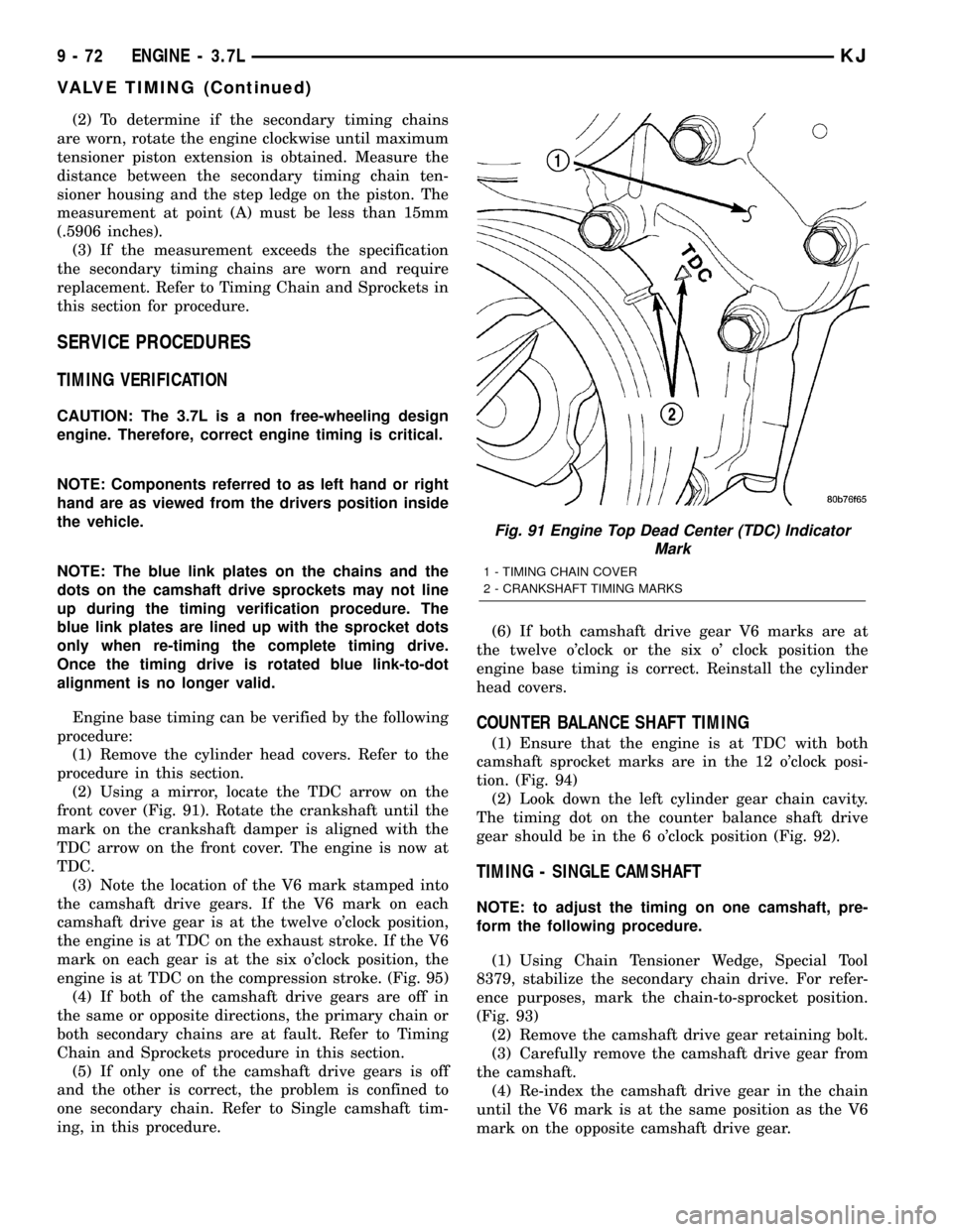
(2) Using a mirror, locate the TDC arrow on the
front cover (Fig. 91). Rotate the crankshaft until the
mark on the crankshaft damper is aligned with the
TDC arrow on the front cover. The engine is now at
TDC.
(3) Note the location of the V6 mark stamped into
the camshaft drive gears. If the V6 mark on each
camshaft drive gear is at the twelve o'clock position,
the engine is at TDC on the exhaust stroke. If the V6
mark on each gear is at the six o'clock position, the
engine is at TDC on the compression stroke. (Fig. 95)
(4) If both of the camshaft drive gears are off in
the same or opposite directions, the primary chain or
both secondary chains are at fault. Refer to Timing
Chain and Sprockets procedure in this section.
(5) If only one of the camshaft drive gears is off
and the other is correct, the problem is confined to
one secondary chain. Refer to Single camshaft tim-
ing, in this procedure.(6) If both camshaft drive gear V6 marks are at
the twelve o'clock or the six o' clock position the
engine base timing is correct. Reinstall the cylinder
head covers.
COUNTER BALANCE SHAFT TIMING
(1) Ensure that the engine is at TDC with both
camshaft sprocket marks are in the 12 o'clock posi-
tion. (Fig. 94)
(2) Look down the left cylinder gear chain cavity.
The timing dot on the counter balance shaft drive
gear should be in the 6 o'clock position (Fig. 92).
TIMING - SINGLE CAMSHAFT
NOTE: to adjust the timing on one camshaft, pre-
form the following procedure.
(1) Using Chain Tensioner Wedge, Special Tool
8379, stabilize the secondary chain drive. For refer-
ence purposes, mark the chain-to-sprocket position.
(Fig. 93)
(2) Remove the camshaft drive gear retaining bolt.
(3) Carefully remove the camshaft drive gear from
the camshaft.
(4) Re-index the camshaft drive gear in the chain
until the V6 mark is at the same position as the V6
mark on the opposite camshaft drive gear.
Fig. 91 Engine Top Dead Center (TDC) Indicator
Mark
1 - TIMING CHAIN COVER
2 - CRANKSHAFT TIMING MARKS
9 - 72 ENGINE - 3.7LKJ
VALVE TIMING (Continued)
Page 1307 of 1803
(1) Inspect air cleaner, induction system and
intake manifold to insure system is dry and clear of
foreign material.
(2) Remove negative battery cable.
(3) Place a shop towel around the spark plugs
when removing them from the engine. This will catch
any fluid that may possibly be in the cylinder under
pressure.
(4) With all spark plugs removed, rotate engine
crankshaft using a breaker bar and socket.
(5) Identify the fluid in the cylinder(s) (i.e., cool-
ant, fuel, oil or other).
(6) Make sure all fluid has been removed from the
cylinders. Inspect engine for damage (i.e., connecting
rods, pistons, valves, etc.)
(7) Repair engine or components as necessary to
prevent this problem from re-occurring.
CAUTION: Squirt approximately one teaspoon of oil
into the cylinders, rotate engine to lubricate the cyl-
inder walls to prevent damage on restart.
(8) Install new spark plugs.
(9) Drain engine oil and remove oil filter.
(10) Install a new oil filter.
(11) Fill engine with specified amount of approved
oil.
(12) Connect negative battery cable.
(13) Start engine and check for any leaks.
STANDARD PROCEDURE - FORM-IN-PLACE
GASKETS AND SEALERS
There are numerous places where form-in-place
gaskets are used on the engine. Care must be taken
when applying form-in-place gaskets to assure
obtaining the desired results.Do not use form-in-
place gasket material unless specified.Bead size,
continuity, and location are of great importance. Too
thin a bead can result in leakage while too much can
result in spill-over which can break off and obstruct
fluid feed lines. A continuous bead of the proper
width is essential to obtain a leak-free gasket.
There are numerous types of form-in-place gasket
materials that are used in the engine area. Mopart
Engine RTV GEN II, MopartATF-RTV, and Mopart
Gasket Maker gasket materials, each have different
properties and can not be used in place of the other.
MOPARtENGINE RTV GEN IIis used to seal
components exposed to engine oil. This material is a
specially designed black silicone rubber RTV that
retains adhesion and sealing properties when
exposed to engine oil. Moisture in the air causes the
material to cure. This material is available in three
ounce tubes and has a shelf life of one year. After one
year this material will not properly cure. Alwaysinspect the package for the expiration date before
use.
MOPARtATF RTVis a specifically designed
black silicone rubber RTV that retains adhesion and
sealing properties to seal components exposed to
automatic transmission fluid, engine coolants, and
moisture. This material is available in three ounce
tubes and has a shelf life of one year. After one year
this material will not properly cure. Always inspect
the package for the expiration date before use.
MOPARtGASKET MAKERis an anaerobic type
gasket material. The material cures in the absence of
air when squeezed between two metallic surfaces. It
will not cure if left in the uncovered tube. The
anaerobic material is for use between two machined
surfaces. Do not use on flexible metal flanges.
MOPARtBED PLATE SEALANTis a unique
(green-in-color) anaerobic type gasket material that
is specially made to seal the area between the bed-
plate and cylinder block without disturbing the bear-
ing clearance or alignment of these components. The
material cures slowly in the absence of air when
torqued between two metallic surfaces, and will rap-
idly cure when heat is applied.
MOPARtGASKET SEALANTis a slow drying,
permanently soft sealer. This material is recom-
mended for sealing threaded fittings and gaskets
against leakage of oil and coolant. Can be used on
threaded and machined parts under all tempera-
tures. This material is used on engines with multi-
layer steel (MLS) cylinder head gaskets. This
material also will prevent corrosion. MopartGasket
Sealant is available in a 13 oz. aerosol can or 4oz./16
oz. can w/applicator.
SEALER APPLICATION
MopartGasket Maker material should be applied
sparingly 1 mm (0.040 in.) diameter or less of sealant
to one gasket surface. Be certain the material sur-
rounds each mounting hole. Excess material can eas-
ily be wiped off. Components should be torqued in
place within 15 minutes. The use of a locating dowel
is recommended during assembly to prevent smear-
ing material off the location.
MopartEngine RTV GEN II or ATF RTV gasket
material should be applied in a continuous bead
approximately 3 mm (0.120 in.) in diameter. All
mounting holes must be circled. For corner sealing, a
3.17 or 6.35 mm (1/8 or 1/4 in.) drop is placed in the
center of the gasket contact area. Uncured sealant
may be removed with a shop towel. Components
should be torqued in place while the sealant is still
wet to the touch (within 10 minutes). The usage of a
locating dowel is recommended during assembly to
prevent smearing material off the location.
9s - 10 ENGINEKJ
ENGINE - 2.4L (Continued)
Page 1324 of 1803
(4) Install cylinder head cover assembly to cylin-
der head. Install all bolts, ensuring the two (2) bolts
containing the sealing washer are located in the cen-
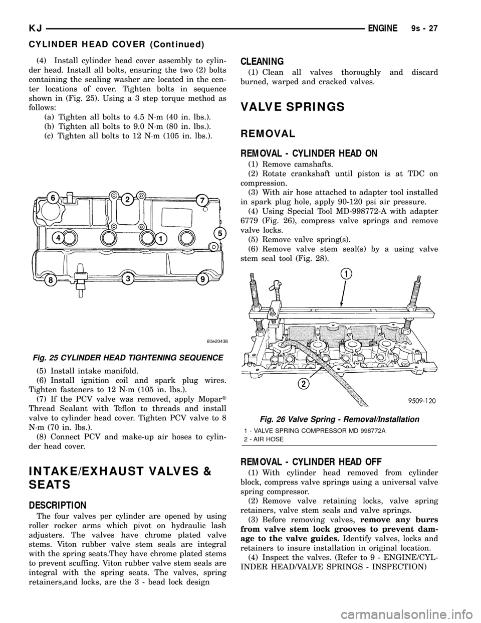
ter locations of cover. Tighten bolts in sequence
shown in (Fig. 25). Using a 3 step torque method as
follows:
(a) Tighten all bolts to 4.5 N´m (40 in. lbs.).
(b) Tighten all bolts to 9.0 N´m (80 in. lbs.).
(c) Tighten all bolts to 12 N´m (105 in. lbs.).
(5) Install intake manifold.
(6) Install ignition coil and spark plug wires.
Tighten fasteners to 12 N´m (105 in. lbs.).
(7) If the PCV valve was removed, apply Mopart
Thread Sealant with Teflon to threads and install
valve to cylinder head cover. Tighten PCV valve to 8
N´m (70 in. lbs.).
(8) Connect PCV and make-up air hoses to cylin-
der head cover.
INTAKE/EXHAUST VALVES &
SEATS
DESCRIPTION
The four valves per cylinder are opened by using
roller rocker arms which pivot on hydraulic lash
adjusters. The valves have chrome plated valve
stems. Viton rubber valve stem seals are integral
with the spring seats.They have chrome plated stems
to prevent scuffing. Viton rubber valve stem seals are
integral with the spring seats. The valves, spring
retainers,and locks, are the 3 - bead lock design
CLEANING
(1) Clean all valves thoroughly and discard
burned, warped and cracked valves.
VALVE SPRINGS
REMOVAL
REMOVAL - CYLINDER HEAD ON
(1) Remove camshafts.
(2) Rotate crankshaft until piston is at TDC on
compression.
(3) With air hose attached to adapter tool installed
in spark plug hole, apply 90-120 psi air pressure.
(4) Using Special Tool MD-998772-A with adapter
6779 (Fig. 26), compress valve springs and remove
valve locks.
(5) Remove valve spring(s).
(6) Remove valve stem seal(s) by a using valve
stem seal tool (Fig. 28).
REMOVAL - CYLINDER HEAD OFF
(1) With cylinder head removed from cylinder
block, compress valve springs using a universal valve
spring compressor.
(2) Remove valve retaining locks, valve spring
retainers, valve stem seals and valve springs.
(3) Before removing valves,remove any burrs
from valve stem lock grooves to prevent dam-
age to the valve guides.Identify valves, locks and
retainers to insure installation in original location.
(4) Inspect the valves. (Refer to 9 - ENGINE/CYL-
INDER HEAD/VALVE SPRINGS - INSPECTION)
Fig. 25 CYLINDER HEAD TIGHTENING SEQUENCE
Fig. 26 Valve Spring - Removal/Installation
1 - VALVE SPRING COMPRESSOR MD 998772A
2 - AIR HOSE
KJENGINE9s-27
CYLINDER HEAD COVER (Continued)
Page 1329 of 1803
INSPECTION
ENGINE BLOCK
(1) Clean cylinder block thoroughly and check all
core hole plugs for evidence of leaking.
(2) If new core plugs are to be installed, (Refer to 9
- ENGINE - STANDARD PROCEDURE - ENGINE
CORE AND OIL GALLERY PLUGS).
(3) Examine block and cylinder bores for cracks or
fractures.
(4) Check block deck surfaces for flatness. Deck
surface must be within service limit of 0.1 mm (0.004
in.).
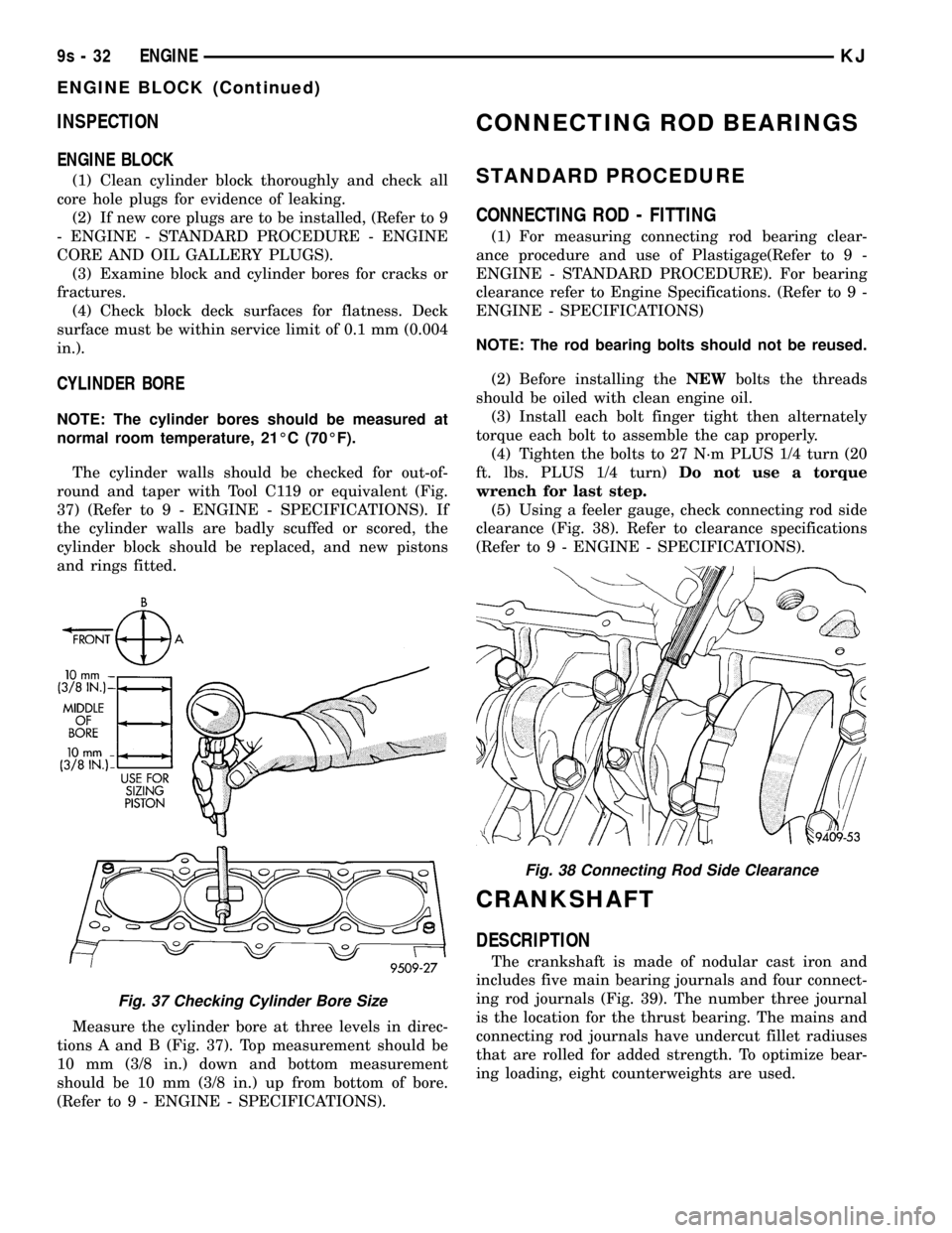
CYLINDER BORE
NOTE: The cylinder bores should be measured at
normal room temperature, 21ÉC (70ÉF).
The cylinder walls should be checked for out-of-
round and taper with Tool C119 or equivalent (Fig.
37) (Refer to 9 - ENGINE - SPECIFICATIONS). If
the cylinder walls are badly scuffed or scored, the
cylinder block should be replaced, and new pistons
and rings fitted.
Measure the cylinder bore at three levels in direc-
tions A and B (Fig. 37). Top measurement should be
10 mm (3/8 in.) down and bottom measurement
should be 10 mm (3/8 in.) up from bottom of bore.
(Refer to 9 - ENGINE - SPECIFICATIONS).
CONNECTING ROD BEARINGS
STANDARD PROCEDURE
CONNECTING ROD - FITTING
(1) For measuring connecting rod bearing clear-
ance procedure and use of Plastigage(Refer to 9 -
ENGINE - STANDARD PROCEDURE). For bearing
clearance refer to Engine Specifications. (Refer to 9 -
ENGINE - SPECIFICATIONS)
NOTE: The rod bearing bolts should not be reused.
(2) Before installing theNEWbolts the threads
should be oiled with clean engine oil.
(3) Install each bolt finger tight then alternately
torque each bolt to assemble the cap properly.
(4) Tighten the bolts to 27 N´m PLUS 1/4 turn (20
ft. lbs. PLUS 1/4 turn)Do not use a torque
wrench for last step.
(5) Using a feeler gauge, check connecting rod side
clearance (Fig. 38). Refer to clearance specifications
(Refer to 9 - ENGINE - SPECIFICATIONS).
CRANKSHAFT
DESCRIPTION
The crankshaft is made of nodular cast iron and
includes five main bearing journals and four connect-
ing rod journals (Fig. 39). The number three journal
is the location for the thrust bearing. The mains and
connecting rod journals have undercut fillet radiuses
that are rolled for added strength. To optimize bear-
ing loading, eight counterweights are used.
Fig. 37 Checking Cylinder Bore Size
Fig. 38 Connecting Rod Side Clearance
9s - 32 ENGINEKJ
ENGINE BLOCK (Continued)
Page 1745 of 1803
COMPASS CALIBRATION - STANDARD
PROCEDURE.........................8M-2
COMPASS DEMAGNETIZING -
STANDARD PROCEDURE...............8M-2
COMPASS MINI-TRIP COMPUTER -
DIAGNOSIS AND TESTING..............8M-6
COMPASS MINI-TRIP ILLUMINATION
BULB - INSTALLATION................8L-75
COMPASS MINI-TRIP ILLUMINATION
BULB - REMOVAL....................8L-74
COMPASS VARIATION ADJUSTMENT -
STANDARD PROCEDURE...............8M-3
COMPASS/MINI-TRIP COMPUTER -
DESCRIPTION........................8M-4
COMPASS/MINI-TRIP COMPUTER -
INSTALLATION.......................8M-8
COMPASS/MINI-TRIP COMPUTER -
OPERATION.........................8M-5
COMPASS/MINI-TRIP COMPUTER -
REMOVAL...........................8M-7
COMPRESSION PRESSURE - DIAGNOSIS
AND TESTING, CYLINDER................9-8
COMPRESSOR CLUTCH - INSPECTION,
A/C................................24-14
COMPRESSOR CLUTCH - INSTALLATION,
A/C................................24-14
COMPRESSOR CLUTCH - REMOVAL, A/C . . 24-13
COMPRESSOR CLUTCH BREAK-IN -
STANDARD PROCEDURE, A/C...........24-12
COMPRESSOR CLUTCH COIL -
DIAGNOSIS AND TESTING, A/C..........24-12
COMPRESSOR CLUTCH RELAY -
DESCRIPTION, A/C...................24-15
COMPRESSOR CLUTCH RELAY -
DIAGNOSIS AND TESTING.............24-15
COMPRESSOR CLUTCH RELAY -
INSTALLATION, A/C...................24-16
COMPRESSOR CLUTCH RELAY -
OPERATION, A/C.....................24-15
COMPRESSOR CLUTCH RELAY -
REMOVAL, A/C......................24-16
COMPRESSOR NOISE - DIAGNOSIS AND
TESTING, A/C.......................24-42
COMPUTER - DESCRIPTION, COMPASS/
MINI-TRIP..........................8M-4
COMPUTER - DIAGNOSIS AND TESTING,
COMPASS MINI-TRIP..................8M-6
COMPUTER - INSTALLATION, COMPASS/
MINI-TRIP..........................8M-8
COMPUTER - OPERATION, COMPASS/
MINI-TRIP..........................8M-5
COMPUTER - REMOVAL, COMPASS/
MINI-TRIP..........................8M-7
CONDENSER - DESCRIPTION, A/C.......24-45
CONDENSER - INSTALLATION, A/C.......24-46
CONDENSER - OPERATION, A/C.........24-45
CONDENSER - REMOVAL, A/C..........24-45
CONDITIONER - DESCRIPTION, HEATER
AND AIR ............................24-1
CONDITIONER - OPERATION, HEATER
AND AIR ............................24-2
CONDITIONS - DIAGNOSIS AND
TESTING, SPARK PLUG................8I-13
CONNECT FITTING - DESCRIPTION,
QUICK.............................14-10
CONNECTING ROD - DESCRIPTION,
PISTON.............................9-49
CONNECTING ROD BEARING - FITTING -
STANDARD PROCEDURE................9-40
CONNECTING ROD BEARING, FITTING.....9-49
CONNECTOR - DESCRIPTION, DATA LINK . 8E-10
CONNECTOR - INSTALLATION
.......8W-01-11
CONNECTOR - INSTALLATION, TRAILER
TOW
..............................8L-61
CONNECTOR - OPERATION, DATA LINK
. . . 8E-10
CONNECTOR - REMOVAL
...........8W-01-11
CONNECTOR - REMOVAL, TRAILER TOW
. . 8L-61
CONNECTOR, GROUND AND SPLICE
INFORMATION - DESCRIPTION
........8W-01-7
CONNECTOR/GROUND/SPLICE LOCATION
- DESCRIPTION
....................8W-91-1
CONSOLE - DESCRIPTION, OVERHEAD
....8M-1
CONSOLE - INSTALLATION, FLOOR
.....23-158
CONSOLE - OPERATION, OVERHEAD
......8M-2
CONSOLE - REMOVAL, FLOOR
.........23-158
CONSOLE DUCT - INSTALLATION, FLOOR
. 24-31
CONSOLE DUCT - REMOVAL, FLOOR
.....24-31CONSOLE LID LATCH - INSTALLATION,
FLOOR............................23-158
CONSOLE LID LATCH - REMOVAL,
FLOOR............................23-158
CONSOLE, REMOVAL - OVERHEAD.......8M-4
CONTAINER - DESCRIPTION, COOLANT
RECOVERY PRESS....................7-19
CONTAINER - OPERATION, COOLANT
RECOVERY PRESS....................7-19
CONTAMINATION - DIAGNOSIS AND
TESTING, BRAKE FLUID................5-26
CONTAMINATION - DIAGNOSIS AND
TESTING, FLUID....................21-125
CONTINUITY - STANDARD PROCEDURE,
TESTING.........................8W-01-9
CONTROL - DESCRIPTION, A/C HEATER . . . 24-16
CONTROL - DESCRIPTION, IGNITION......8I-1
CONTROL - DESCRIPTION, SPEED........8P-1
CONTROL - INSTALLATION, A/C HEATER . . 24-17
CONTROL - OPERATION, IGNITION........8I-1
CONTROL - OPERATION, SPEED..........8P-1
CONTROL - REMOVAL, A/C HEATER......24-17
CONTROL - TORQUE, SPEED............8P-2
CONTROL ARM - DESCRIPTION, LOWER . . . 2-21
CONTROL ARM - INSTALLATION, LOWER . . 2-10,
2-21
CONTROL ARM - INSTALLATION, UPPER . . . 2-21
CONTROL ARM - OPERATION, LOWER.....2-21
CONTROL ARM - REMOVAL, LOWER . . 2-10,2-21
CONTROL ARM - REMOVAL, UPPER......2-20
CONTROL ASSEMBLY WINDOW
DEFOGGER FUNCTION - DIAGNOSIS
AND TESTING, REAR HVAC.............8G-9
CONTROL CABLE - INSTALLATION,
THROTTLE..........................14-46
CONTROL CABLE - REMOVAL,
THROTTLE..........................14-45
CONTROL ILLUMINATION BULB -
INSTALLATION, HEATER-A/C............8L-78
CONTROL ILLUMINATION BULB -
REMOVAL, HEATER-A/C...............8L-78
CONTROL INFORMATION (VECI) LABEL -
DESCRIPTION, VEHICLE EMISSION.....Intro.-8
CONTROL MODULE - DESCRIPTION,
AIRBAG.............................8O-9
CONTROL MODULE - DESCRIPTION,
BODY...............................8E-2
CONTROL MODULE - DESCRIPTION,
SIDE IMPACT AIRBAG.................8O-43
CONTROL MODULE - DESCRIPTION,
TRANSMISSION......................8E-18
CONTROL MODULE - DIAGNOSIS AND
TESTING, BODY.......................8E-7
CONTROL MODULE - INSTALLATION....23-183
CONTROL MODULE - INSTALLATION,
AIRBAG............................8O-12
CONTROL MODULE - INSTALLATION,
BODY...............................8E-7
CONTROL MODULE - INSTALLATION,
SIDE IMPACT AIRBAG.................8O-45
CONTROL MODULE - OPERATION,
AIRBAG............................8O-10
CONTROL MODULE - OPERATION, BODY . . . 8E-5
CONTROL MODULE - OPERATION, SIDE
IMPACT AIRBAG.....................8O-43
CONTROL MODULE - OPERATION,
TRANSMISSION......................8E-18
CONTROL MODULE - REMOVAL........23-183
CONTROL MODULE - REMOVAL, AIRBAG . 8O-11
CONTROL MODULE - REMOVAL, BODY....8E-7
CONTROL MODULE - REMOVAL, SIDE
IMPACT AIRBAG.....................8O-44
CONTROL MOTOR - DESCRIPTION, IDLE
AIR ...............................14-35
CONTROL MOTOR - INSTALLATION, IDLE
AIR ...............................14-36
CONTROL MOTOR - OPERATION, IDLE
AIR ...............................14-35
CONTROL MOTOR - REMOVAL, IDLE AIR . . 14-36
CONTROL RELAY - DESCRIPTION,
TRANSMISSION.....................21-168
CONTROL RELAY - OPERATION,
TRANSMISSION
.....................21-168
CONTROL SWITCH - DESCRIPTION
.....23-184
CONTROL SWITCH - DIAGNOSIS AND
TESTING
..........................23-184
CONTROL SWITCH - INSTALLATION
.....23-184
CONTROL SWITCH - OPERATION
.......23-184CONTROL SWITCH - REMOVAL........23-184
CONTROL SYSTEM - DESCRIPTION,
EMISSION...........................25-1
CONTROL SYSTEM - DESCRIPTION,
EVAPORATION.......................25-24
CONTROLLER ANTILOCK BRAKE -
INSTALLATION.......................8E-10
CONTROLLER ANTILOCK BRAKE -
REMOVAL..........................8E-10
CONVERTER - DESCRIPTION, CATALYTIC . . . 11-2
CONVERTER - DESCRIPTION, TORQUE . . . 21-162
CONVERTER - INSPECTION, CATALYTIC....11-3
CONVERTER - INSTALLATION, CATALYTIC . . 11-3
CONVERTER - INSTALLATION, TORQUE . . 21-167
CONVERTER - OPERATION, TORQUE....21-166
CONVERTER - REMOVAL, CATALYTIC......11-2
CONVERTER - REMOVAL, TORQUE......21-167
CONVERTER HOUSING FLUID LEAK -
DIAGNOSIS AND TESTING.............21-80
COOLANT - DESCRIPTION, ENGINE........0-3
COOLANT LOW INDICATOR -
DESCRIPTION.......................8J-15
COOLANT LOW INDICATOR - OPERATION . 8J-16
COOLANT RECOVERY PRESS
CONTAINER - DESCRIPTION.............7-19
COOLANT RECOVERY PRESS
CONTAINER - OPERATION...............7-19
COOLANT TEMPERATURE SENSOR -
DESCRIPTION, ENGINE.................7-19
COOLANT TEMPERATURE SENSOR -
INSTALLATION, ENGINE................7-21
COOLANT TEMPERATURE SENSOR -
OPERATION, ENGINE...................7-20
COOLANT TEMPERATURE SENSOR -
REMOVAL, ENGINE....................7-20
COOLANT THERMOSTAT - OPERATION,
ENGINE.............................7-21
COOLER - DESCRIPTION, FLUID.........19-20
COOLER - DESCRIPTION, TRANS.........7-32
COOLER - INSTALLATION, FLUID........19-20
COOLER - OPERATION, FLUID..........19-20
COOLER - REMOVAL, FLUID............19-20
COOLING, SPECIAL TOOLS..............7-14
COOLING SYSTEM - OPERATION..........7-2
COOLING SYSTEM - REVERSE
FLUSHING - STANDARD PROCEDURE.....7-12
COOLING SYSTEM 3.7L ENGINE -
DESCRIPTION.........................7-1
COOLING SYSTEM 3.7L ENGINE -
STANDARD PROCEDURE, DRAINING......7-12
COOLING SYSTEM 3.7L ENGINE -
STANDARD PROCEDURE, REFILLING......7-12
COOLING SYSTEM DIAGNOSIS CHART -
DIAGNOSIS AND TESTING...............7-6
COOLING SYSTEM LEAKS - DIAGNOSIS
AND TESTING.........................7-4
COOLING SYSTEM REQUIREMENTS -
DESCRIPTION........................24-1
COOLING SYSTEM ROUTING 3.7L
ENGINE - DESCRIPTION.................7-2
CORE - DESCRIPTION, HEATER.........24-52
CORE - INSTALLATION, HEATER.........24-53
CORE - OPERATION, HEATER...........24-52
CORE - REMOVAL, HEATER............24-52
CORE AND OIL GALLERY PLUGS -
STANDARD PROCEDURE, ENGINE........9-10
COURTESY LAMP BULB - INSTALLATION . . 8L-76
COURTESY LAMP BULB - REMOVAL.....8L-75
COURTESY LAMP REPLACEMENT -
STANDARD PROCEDURE...............8M-2
COURTESY LAMP UNIT - INSTALLATION . . 8L-77
COURTESY LAMP UNIT - REMOVAL......8L-76
COVER - DESCRIPTION, STRUCTURAL.....9-55
COVER - FRONT - INSTALLATION, SEAT
BACK.............................23-167
COVER - FRONT - INSTALLATION, SEAT
CUSHION..........................23-167
COVER - FRONT - REMOVAL, SEAT BACK . 23-166
COVER - FRONT - REMOVAL, SEAT
CUSHION..........................23-167
COVER - INSTALLATION, COWL TRIM . . . 23-157
COVER - INSTALLATION, INSTRUMENT
PANEL TOP
........................23-153
COVER - INSTALLATION, STRUCTURAL
....9-55
COVER - OPERATION, STRUCTURAL
......9-55
COVER - REAR - INSTALLATION, SEAT
BACK
.............................23-169
COVER - REAR - REMOVAL, SEAT BACK
. 23-169
6 INDEXKJ
Description Group-Page Description Group-Page Description Group-Page
Page 1748 of 1803
ENGINE - DESCRIPTION, COOLING
SYSTEM 3.7L.........................7-1
ENGINE - DESCRIPTION, COOLING
SYSTEM ROUTING 3.7L.................7-2
ENGINE - INSTALLATION, 3.7L . . . 7-17,7-18,7-22
ENGINE - REMOVAL, 3.7L...........7-17,7-21
ENGINE - STANDARD PROCEDURE,
DRAINING COOLING SYSTEM 3.7L........7-12
ENGINE - STANDARD PROCEDURE,
REFILLING COOLING SYSTEM 3.7L.......7-12
ENGINE BLOCK - CLEANING.............9-39
ENGINE BLOCK - DESCRIPTION..........9-39
ENGINE BLOCK - INSPECTION...........9-40
ENGINE COOLANT - DESCRIPTION.........0-3
ENGINE COOLANT TEMPERATURE
SENSOR - DESCRIPTION...............7-19
ENGINE COOLANT TEMPERATURE
SENSOR - INSTALLATION...............7-21
ENGINE COOLANT TEMPERATURE
SENSOR - OPERATION.................7-20
ENGINE COOLANT TEMPERATURE
SENSOR - REMOVAL...................7-20
ENGINE COOLANT THERMOSTAT -
OPERATION..........................7-21
ENGINE CORE AND OIL GALLERY PLUGS
- STANDARD PROCEDURE..............9-10
ENGINE CRADLE CROSSMEMBER -
INSTALLATION........................13-6
ENGINE CRADLE CROSSMEMBER -
REMOVAL...........................13-6
ENGINE DIAGNOSIS - INTRODUCTION -
DIAGNOSIS AND TESTING.................9-4
ENGINE DIAGNOSIS - LUBRICATION -
DIAGNOSIS AND TESTING...............9-7
ENGINE DIAGNOSIS - MECHANICAL -
DIAGNOSIS AND TESTING...............9-6
ENGINE DIAGNOSIS - PERFORMANCE -
DIAGNOSIS AND TESTING...............9-4
ENGINE FIRING ORDER, 2.4L 4-
CYLINDER...........................8I-2
ENGINE FIRING ORDER, 3.7L V-6.........8I-2
ENGINE GASKET SURFACE
PREPARATION - STANDARD
PROCEDURE..........................9-9
ENGINE OIL - STANDARD PROCEDURE....9-61
ENGINE OIL LEAK - DIAGNOSIS AND
TESTING............................9-60
ENGINE OIL PRESSURE - DIAGNOSIS
AND TESTING........................9-60
ENGINE, SPECIAL TOOLS - 3.7L..........9-15
ENGINE, SPECIFICATIONS - 3.7L.........9-12
ENGINE TEMPERATURE GAUGE -
DESCRIPTION.......................8J-18
ENGINE TEMPERATURE GAUGE -
OPERATION.........................8J-18
ENGINES - GENERATOR RATINGS, GAS . . . 8F-23
ENTRY MODULE - DESCRIPTION,
REMOTE KEYLESS....................8N-7
ENTRY MODULE - DIAGNOSIS AND
TESTING, REMOTE KEYLESS............8N-7
ENTRY MODULE - INSTALLATION,
REMOTE KEYLESS....................8N-7
ENTRY MODULE - OPERATION, REMOTE
KEYLESS............................8N-7
ENTRY MODULE - REMOVAL, REMOTE
KEYLESS............................8N-7
ENTRY TRANSMITTER - DIAGNOSIS AND
TESTING, REMOTE KEYLESS............8N-8
ENTRY TRANSMITTER -
SPECIFICATIONS, REMOTE KEYLESS......8N-9
EQUIPMENT - STANDARD PROCEDURE,
REFRIGERANT SYSTEM SERVICE........24-40
ERASING TRANSMITTER CODES -
STANDARD PROCEDURE...............8M-8
EVACUATE - STANDARD PROCEDURE,
REFRIGERANT SYSTEM...............24-41
EVAPORATION CONTROL SYSTEM -
DESCRIPTION.......................25-24
EVAPORATOR - DESCRIPTION, A/C.......24-49
EVAPORATOR - INSTALLATION, A/C......24-49
EVAPORATOR - OPERATION, A/C........24-49
EVAPORATOR - REMOVAL, A/C..........24-49
EVAP/PURGE SOLENOID - DESCRIPTION . . 25-27
EVAP/PURGE SOLENOID - INSTALLATION
. 25-27
EVAP/PURGE SOLENOID - OPERATION
....25-27
EVAP/PURGE SOLENOID - REMOVAL
.....25-27
EXCEPT DIESEL - TORQUE
.............8F-23
EXHAUST MANIFOLD - DESCRIPTION
.....9-69EXHAUST MANIFOLD - INSTALLATION.....9-70
EXHAUST MANIFOLD - REMOVAL.........9-69
EXHAUST SYSTEM - DESCRIPTION.......11-1
EXHAUST SYSTEM - DIAGNOSIS AND
TESTING............................11-2
EXTENSION HOUSING BUSHING -
NV3550 - INSTALLATION...............21-74
EXTENSION HOUSING BUSHING -
NV3550 - REMOVAL..................21-73
EXTENSION HOUSING SEAL - NV1500 -
INSTALLATION.......................21-32
EXTENSION HOUSING SEAL - NV1500 -
REMOVAL..........................21-32
EXTENSION HOUSING SEAL - NV3550 -
INSTALLATION.......................21-74
EXTENSION HOUSING SEAL - NV3550 -
REMOVAL..........................21-74
EXTERIOR - DESCRIPTION, LAMPS/
LIGHTING...........................8L-2
EXTERIOR - DIAGNOSIS AND TESTING,
LAMPS/LIGHTING.....................8L-7
EXTERIOR - OPERATION, LAMPS/
LIGHTING...........................8L-5
EXTERIOR - SPECIFICATIONS,
LAMPS/LIGHTING....................8L-15
EXTERIOR HANDLE - INSTALLATION....23-123,
23-130,23-136
EXTERIOR HANDLE - REMOVAL . 23-123,23-130,
23-136
EXTERIOR NAME PLATES -
INSTALLATION......................23-141
EXTERIOR NAME PLATES - REMOVAL . . . 23-140
FAN - ELECTRIC - DESCRIPTION,
RADIATOR...........................7-26
FAN - ELECTRIC - INSTALLATION,
RADIATOR...........................7-27
FAN - ELECTRIC - OPERATION,
RADIATOR...........................7-26
FAN - ELECTRIC - REMOVAL, RADIATOR . . . 7-26
FAN - VISCOUS - CLEANING, RADIATOR . . . 7-29
FAN - VISCOUS - DESCRIPTION,
RADIATOR...........................7-27
FAN - VISCOUS - INSPECTION,
RADIATOR...........................7-29
FAN - VISCOUS - INSTALLATION,
RADIATOR...........................7-29
FAN - VISCOUS - OPERATION,
RADIATOR...........................7-27
FAN - VISCOUS - REMOVAL, RADIATOR....7-28
FAN DRIVE - DIAGNOSIS AND TESTING,
VISCOUS............................7-28
FASCIA - INSTALLATION, FRONT.........13-2
FASCIA - INSTALLATION, REAR..........13-2
FASCIA - REMOVAL, FRONT.............13-1
FASCIA - REMOVAL, REAR..............13-2
FASCIA SUPPORT - INSTALLATION,
REAR...............................13-3
FASCIA SUPPORT - REMOVAL, REAR......13-3
FASTENER IDENTIFICATION -
DESCRIPTION......................Intro.-1
FENDER - INSTALLATION, FRONT.......23-141
FENDER - REMOVAL, FRONT..........23-141
FILL - STANDARD PROCEDURE, FLUID
DRAIN......................21-208,21-246
FILL - STANDARD PROCEDURE,
TRANSMISSION.....................21-128
FILL DOOR/HOUSING - INSTALLATION,
FUEL.............................23-141
FILL DOOR/HOUSING - REMOVAL, FUEL . 23-141
FILL/CHECK LOCATIONS - DESCRIPTION,
FLUID...............................0-4
FILLER CAP - DESCRIPTION, FUEL.......25-27
FILLER CAP - OPERATION, FUEL........25-27
FILTER - DESCRIPTION, FUEL............14-7
FILTER - INSTALLATION, FUEL...........14-8
FILTER - INSTALLATION, INLET..........14-28
FILTER - INSTALLATION, OIL............9-63
FILTER - REMOVAL, FUEL...............14-7
FILTER - REMOVAL, INLET.............14-28
FILTER - REMOVAL, OIL
................9-63
FILTER REPLACEMENT - STANDARD
PROCEDURE, FLUID
.................21-126
FINESSE SANDING/BUFFING &
POLISHING - DESCRIPTION
...........23-163
FINISH - DESCRIPTION, BASE
COAT/CLEAR COAT
..................23-162
FIRING ORDER, 2.4L 4-CYLINDER -
ENGINE
..............................8I-2FIRING ORDER, 3.7L V-6 - ENGINE........8I-2
FITTING - CONNECTING ROD BEARING....9-49
FITTING - DESCRIPTION, QUICK
CONNECT...........................14-10
FITTING - MAIN BEARING...............9-45
FITTING - STANDARD PROCEDURE,
CONNECTING ROD BEARING............9-40
FITTING - STANDARD PROCEDURE,
PISTON.............................9-50
FITTING - STANDARD PROCEDURE,
PISTON RING........................9-52
FITTINGS - STANDARD PROCEDURE,
QUICK-CONNECT.....................14-10
FLARE MOLDINGS - INSTALLATION,
FRONT WHEEL OPENING.............23-145
FLARE MOLDINGS - INSTALLATION,
REAR WHEEL OPENING..............23-145
FLARE MOLDINGS - REMOVAL, FRONT
WHEEL OPENING...................23-145
FLARE MOLDINGS - REMOVAL, REAR
WHEEL OPENING...................23-145
FLARING - STANDARD PROCEDURE,
DOUBLE INVERTED.....................5-8
FLARING - STANDARD PROCEDURE, ISO....5-8
FLASHER - DESCRIPTION, COMBINATION . 8L-19
FLASHER - OPERATION, COMBINATION . . . 8L-19
FLEX PLATE - INSTALLATION............9-49
FLEX PLATE - REMOVAL................9-49
FLIP-UP GLASS - INSTALLATION.......23-136
FLIP-UP GLASS - REMOVAL...........23-136
FLIP-UP GLASS AJAR SWITCH -
DESCRIPTION.......................8L-77
FLIP-UP GLASS AJAR SWITCH -
OPERATION.........................8L-77
FLIP-UP GLASS LATCH - INSTALLATION . 23-136
FLIP-UP GLASS LATCH - REMOVAL.....23-136
FLIP-UP GLASS RELEASE SWITCH -
DIAGNOSIS AND TESTING..............8N-5
FLIP-UP GLASS SUPPORT CYLINDER -
INSTALLATION......................23-139
FLIP-UP GLASS SUPPORT CYLINDER -
REMOVAL.........................23-139
FLOOR - DEFROST DOO - INSTALLATION . . 24-37
FLOOR - DEFROST DOOR - REMOVAL....24-36
FLOOR - DEFROST DOOR ACTUATOR -
INSTALLATION.......................24-25
FLOOR - DEFROST DOOR ACTUATOR -
REMOVAL..........................24-24
FLOOR CONSOLE - INSTALLATION......23-158
FLOOR CONSOLE - REMOVAL..........23-158
FLOOR CONSOLE DUCT - INSTALLATION . . 24-31
FLOOR CONSOLE DUCT - REMOVAL.....24-31
FLOOR CONSOLE LID LATCH -
INSTALLATION......................23-158
FLOOR CONSOLE LID LATCH - REMOVAL . 23-158
FLOOR DUCT - INSTALLATION..........24-32
FLOOR DUCT - REMOVAL..............24-32
FLOOR MATS - INSTALLATION, CARPETS . 23-158
FLOOR MATS - REMOVAL, CARPETS....23-158
FLOOR SHIFT BOOT - INSTALLATION,
4WD .............................23-156
FLOOR SHIFT BOOT - REMOVAL, 4WD . . . 23-156
FLOW AND PRESSURE - DIAGNOSIS
AND TESTING, POWER STEERING........19-3
FLOW MANAGEMENT VALVE -
DESCRIPTION........................14-6
FLOW MANAGEMENT VALVE -
INSTALLATION........................14-7
FLOW MANAGEMENT VALVE -
OPERATION..........................14-6
FLOW MANAGEMENT VALVE - REMOVAL . . . 14-6
FLUID - DESCRIPTION, AUTOMATIC
TRANSMISSION.......................0-2
FLUID - DIAGNOSIS AND TESTING,
CAUSES OF BURNT..................21-125
FLUID - OPERATION, AUTOMATIC
TRANSMISSION.......................0-4
FLUID AND FILTER REPLACEMENT -
STANDARD PROCEDURE..............21-126
FLUID CAPACITIES - SPECIFICATIONS......0-4
FLUID CONTAMINATION - DIAGNOSIS
AND TESTING......................21-125
FLUID CONTAMINATION - DIAGNOSIS
AND TESTING, BRAKE
..................5-26
FLUID COOLER - DESCRIPTION
.........19-20
FLUID COOLER - INSTALLATION
.........19-20
FLUID COOLER - OPERATION
...........19-20
FLUID COOLER - REMOVAL
............19-20
KJINDEX 9
Description Group-Page Description Group-Page Description Group-Page